COMPUTER-CONTROLLED CUTTING | WEEK 03
Vinyl Cutting
A0 Link to group assignment.
You can see the group assignment hereFor the vinyl assigment I've contacted with a friend who is professionally dedicated to vinyl cutting. He has a business focused on vinyls for cars, t-shirt, stores... He has to machines regular one that only cuts vinyl and another one that can print and cut the vinyl.
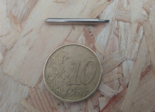
The basic machine is a -------- and has a maximum width of 1m. It doesn't count with sensors of any type so you have to "explain" to the machine the type of vinyl and the size of it before start the cut. To cut the vinyl the machine has a very tiny blade which is the part that cut the material. You can see how tiny is in this picture
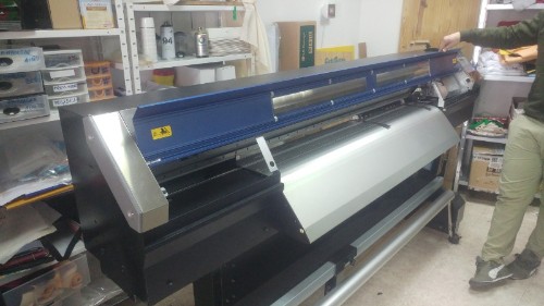
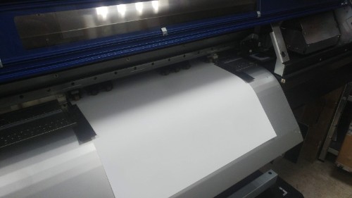
The second machine is a ------ the maximum size to cut is 2m and has sensors and a system of ink inyectors to create vinyls of different colors before cut them in pieces. This is a real vinyl cutting machine way more expensive than the first one.
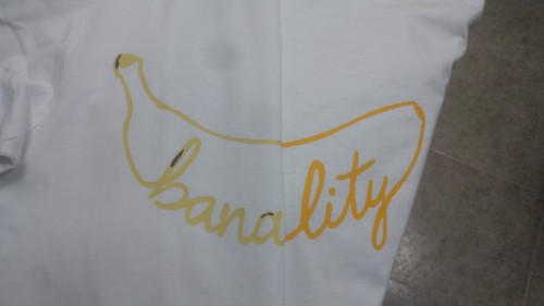
He let me use both of them and show me the different techniques and ways to work with vinyl. first we did a sticker in th first machine and then two t-shirts with the same idea but one was printed in white vinyl and the other was cut directly from a yellow vinyl.
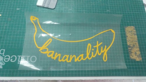
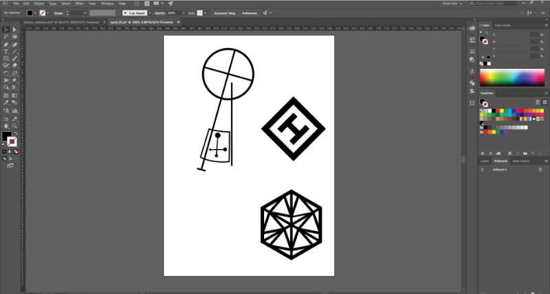
To try the vinyl machine I have chosen a design made by me, It's the logo for a brand that I have with a friend, Paulo Futre focused on funny objects not really useful. I've chosen this design because it's easy not vay complicate and I already have a vectorial version of it in my computer. I did it by hand and then vectorize with Adobe Illustrator.
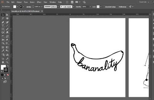
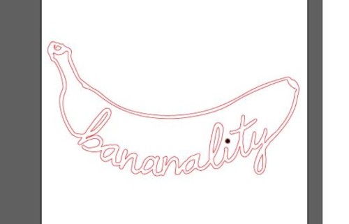
The program to send the drawing to the cuttign machine has some design options but I did everything on illustrator and send the vector file ready to cut. These means that I scale and erase the interior of the figure before send it to the program, the reason to erase the hatch andl leave only the exterior line is because It's the only element that the machine reads.
The program is called "FlexiSTARTER SECABO and it's very basic.
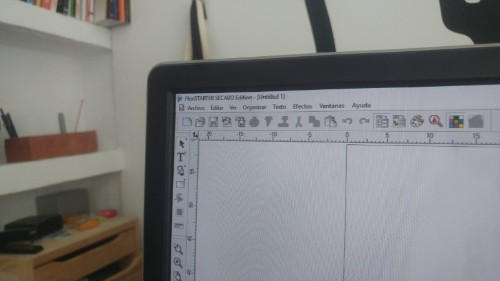
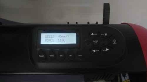
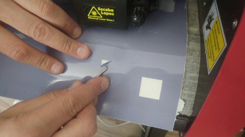
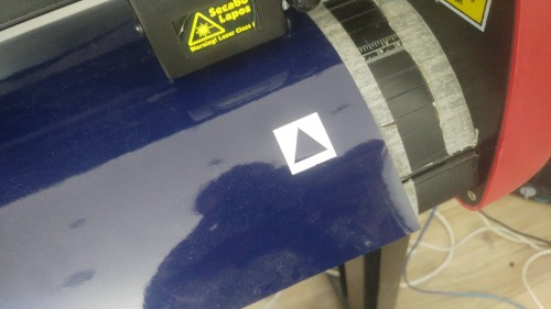
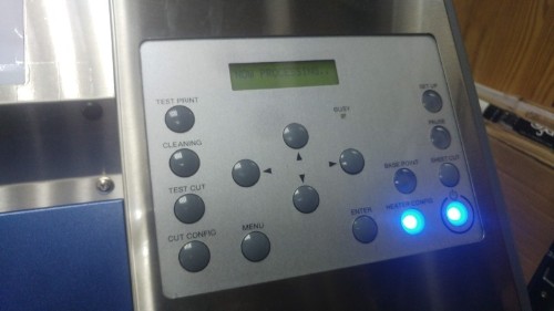
Before send the file to the machine we charge the vinyl and do a first try to calibrate the blade pression. It's a very simple process that you do directly i the cutting machine, which has a small screen and a context menu that let you pick the presion and make a trial. The trial consist into cut a square with a triangle inside, if the paper in the back it's ok and you can take of the square without move the triangle the presion is correct, we did two or three trials before find the correct parameter for the vinyl that I've picked.
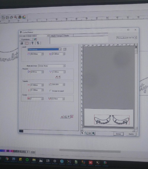
After we have the machine calibrated the got back to the computer and send the file. To send the file the program has a submenu very similar to the one that you can find in a regular printer but even more simple. The important parameters to see is the size of the paper, the size of the drawing and the mirror option, which it's only necessary when you are using thermoadhesive vinyl, the one used for textiles.
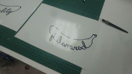
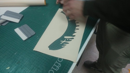
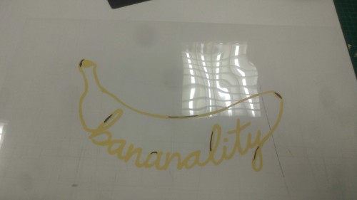
When the machine had ended with the cutting part is was time for the post-productions of the sticker: with a small tool similar hook I had to take off every part of the vinyl that I don't want to use. We did two one in mirror to see the diference between them. Here is the result.
To transfer the vinyl to the final surface is necessary to use a special sheet of plastic or paper called "transfer paper", obviously. With care and the help of a cplastic piece similar to a credit card I put the tranfer, which is more rigid and makes easier to fixed the vinyl in the final place.
Now it's time to put the the sticer in his final place. first I tried with the mirrored one. Using masking tape you can find the right position and only then take of the back part and positionate the vinyl, then I applied presion with the credit card and, finally, took off the transfer from the top. Easy.
.jpg)
.jpg)
.jpg)
.jpg)
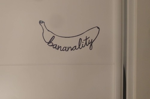
Here you can see the final result fixed in the door of my room's closet.
Regular thermoadhesive vinyl must be cut mirrored, the reason is because the adhesive part is situated in the face where you do the cut. This is how we made the first copy, tha you can see here.
To try the other machine we modified a little the logo to have areas in two colors (yellow and black) both color where printed by the machine in a white vinyl. First we charge the vinyl paper in the cutting machine, it calibrated the size by it self and put the vinyl correctly before start. It's interesting to say that the machine was a little hot, the reason is that it helps the ink to get dry faster, my friend told me that without that the ink needs at least four hours to get dry.
The program that I need to use in this case was a different one and a little bit more complicated, but not much.
.jpg)
.jpg)
.jpg)
It works like a regular plotter and after the print it's done starts with the cutting like the other machine. It's important to say that even with a precise machine it's very recommended to make an offset of the contour and print more area than the one that is going to be cut, by doing these it can be garantified that there won't be white parts at the end.
Now it's time to put the vinyl in the t-shirt. To do this we are going to use a special iron designed for it but, before that, we need to positionate the vinyl in the t-shirt.
.jpg)
.jpg)
To fixed the vinyl in the t-shirt we need to applied hot during 16 seconds two times, the recommended temperature is 160 celsius degrees.
.jpg)
.jpg)
.jpg)
My last picture is a comparation between both t-shirt and the aspect of the vinyls.
So... My tutor encourage me to use the machine from the Fablab too, a good opportunity to personalize my new computer. I prepare some designs in illustrator and copy them in the computer for the vynil cutter.
The machine that I'm going to use is a Roland cam-1 GS-24. and it works like a printer, I mean you have to send the files from illustrator from the printer manager.
I've put the vynil inside and run the test to see the height of the cutter.
.jpg)
.jpg)
It's working well with 60g of pressure so I can send now the file. There are only two importan thing to have in mind: The size of the piece were you are going to cut and don't use lines, only fills so the program don't cut the weight of the line too.
.jpg)
.jpg)
Now It's time to put them in my computer. In the fab lab we don't have transfer so I had to do it without it. I have to say that is harder and the result is not as good as with the transfer, I mean it works well for small things with little detail but for more it' impossible.
.jpg)
Here is my hero shot ¡Tachaaan!
.jpg)
Laser Cutting
I didn't characterize the laser machines from the fablab, as part of a company focused on laser cutting I thought that it could be ore interesting to explain the machines that I use for work every day. We have been doing some modifications to solve somo problems and improve the funcioning of them that I would like to share at fabacademy.
We have three machines at the factory, the first two of them are the typical kind of laser cutting machines. The first one has an area of 1600mm x 1000mm and can cut material of 10mm of thickness, the second one can cut the same thickness but the area is bigger: 1500mmx2500m. The third machine is designed only for engraving, is very fast doing this process but not so powerful as the other ones. The maximum area is 110x110mm, it can be bigger if we use another lens but the quality of the engrave will be worse. All of them are CO2 machines and the most important difference between the two of them that can cut is that the biggest it's not closed which makes smoke produced by the laer a real problem that we've been months trying to fix.


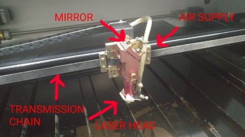
The laser is in the backpart of the machine and goes by mirrors to the laser head when it's fovused through a lens into the material. the laser head also has a supply of compressed air to prevent fire and mantain the cut clean. In the picture you can see a piece of masking tape fixed in the laser head. Well, this is a little trick that reduce the size of the the hole to the minimum making the cut cleaner.
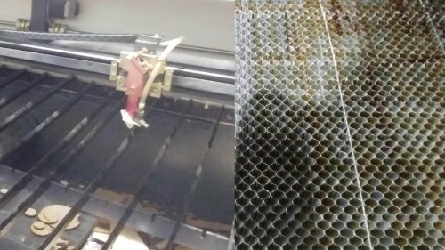
We have two types of cutting tables that we swich depending on the type of work, and the size of the pieces. One is panel of steelhoneycomb, which works fine with small pieces, the problem with this table is that the back of the pieces is usually burned in many places. The reason is that the laser "rebounds" in the steel of the honeycomb. that's why we usually prefer to use a table made by beams of steal, not so good for small pieces but still very usuful for most part of the job.
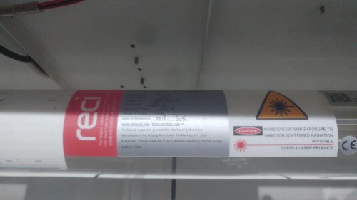
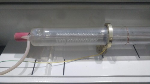
The tube is in the back and it's the most expensive part of the machine. It's very fragil and dangerous so it's always in a closed space that it can be open during while the machine is on. It needs to be refrigerated to work correctly.
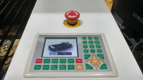
The basic system of the machine is based on linux and lets you control basic parameters, manage files or upload files using a pendrive, without connect the machine directly to a computer. Anyway it's easier to do everything from a computer, but this screen can be very useful for quick changes in the parameters.
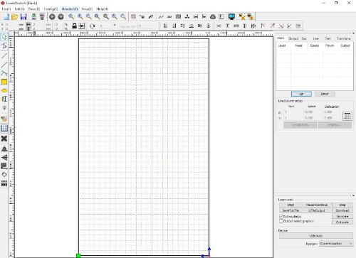
To send the files and control the machine we use a program called "Laserworks v6" that export the files with the extension ".mol" which is the only one read by the machine software.
Engraving machine
The laser engraving machine is very small and needs a computer always connected to work. It doesn't have a system to evacuate the smoke, so we had to adapt a tube and connect it to the central ventilation of the factory. We are still trying to create better solution.
.jpg)
.jpg)
First, I created a piece to test the dimensions of the joints. I did it parametric so it will be easier and could be use for any material.
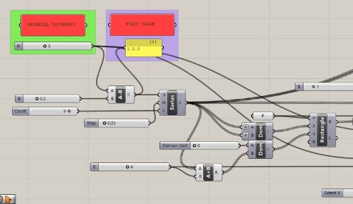
It has been made to pick only specify the material thickness and the first value to start with the different values. Basically, it's a rectangle from where I've had sustracted the space for the joints. The width is 0.05mm more in each of them. Here you can see the pieces ready to be exported. I made more than one option to try different materials.
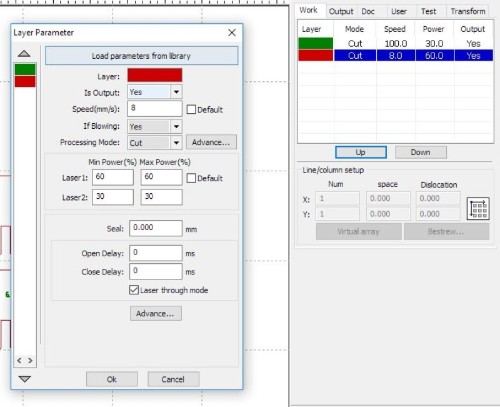
I've exported one of them to the laser cutting program, called "laserworks v6" and then prepare the parameters
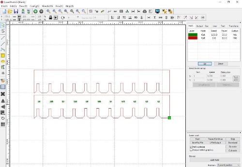
You can use predefined values from the library or just typing it by yourself. there are two important values to change, speed and minimum and maximum power. There is another option just for engraving that I won't use for this work. Every color is a different kind of cutting, in this case green is a softer and faster cut that can cut the material, only mark it. Red is the color used for cutting.
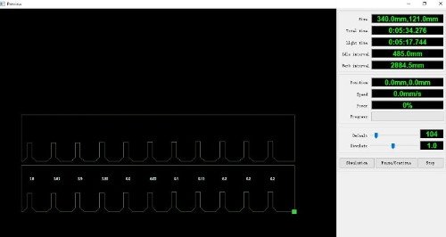
the programhas a very interesting option called "preview" that makes an estimated time calculation. The precision is not always perfect but it works better with cutting and marking than engraving.
After cut them and try diferent material I found that usually rigid materials as MDF wood need an offset of 0.1 - 0.15 mm. For other materials such as cardboard that ar emore flexible is recomended to use a bigger one 0.2mm
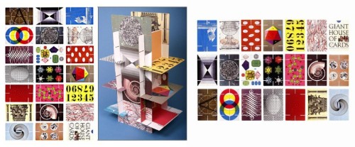
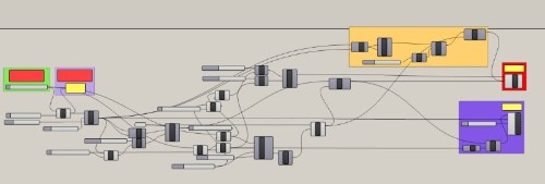
As reference for my press-fit kit I thought in the card game designed by charles Eames. But I wanted to add one more condition: inclined joints. The whole project was made using rhino and grasshopper.
.jpg)
First I've sketched a non parametric drawing of the piece. Based on that I've started to define the different elements in grasshopper. Firstly I've focused in the ortogonal joints and create the point where the joint will be.
.jpg)
Then I've put the rectangles for the difference in the right place and connect the size of the main rectangle to the height and width of the joints.
.jpg)
.jpg)
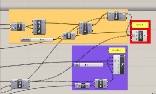
The second part is introduce the inclined joints in the main rectangle, I did it by copying and rotate the ortogonal joints.
.jpg)
.jpg)
.jpg)
When I had all of them I only needed to use the command region difference to create the final piece.
.jpg)
The last part is replicate and "bake" a grig of pieces. Bake means to transform the parametric drawign into a regular cad drawing that can be exported to dxf, the only kind of file accepted by the lasercutting machine.
.jpg)
I follow the same steps that I did during to try the laser machine and cut the pieces based on the thickness of the cardboard. Everything went fine and I'm very happy with the result, it's looks like something between japanese architecture and star wars!
.jpg)
.jpg)
.jpg)
.jpg)
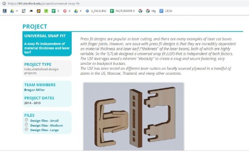
I was interested in trying another kind of joints. there are many books and catalogues of different kinds of joints. some of them have been adapted to digital fabrication. While I was looking for them I found this type designed at standford university. I decided that it will be interestign to do some object with it.
I chose a little table because it was easy and we really need one for our printer. The work went fine and here you can see the pictures of the process.
.jpg)
.jpg)
.jpg)
.jpg)
I want to try to do something with flexures. surfing in the web I've found a example file from instructables and printed the different pattens. Here you can see the result. download flexures
.jpg)
.jpg)
.jpg)
.jpg)
.jpg)
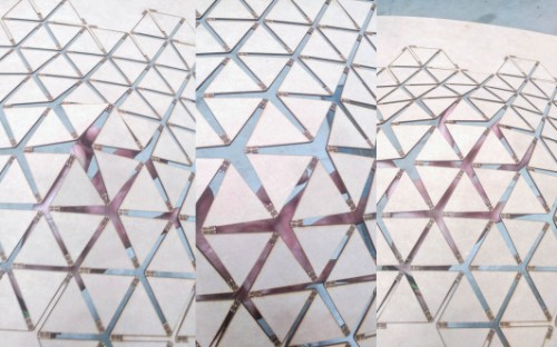
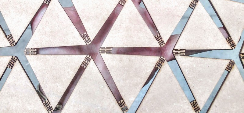
Not I want to replicate one of them in the joints of the origami pattern that I will use in my final project. I draw the origami pattern in rhino, starting by one module i replicated with a polar matrix to have the basic unit of six triangles and then create a grid with more than one module.
.jpg)
.jpg)
.jpg)
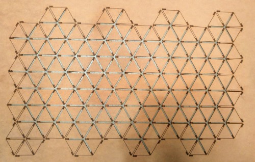
I sent the result to the lasercutting program and cut a first try in a piece of MDF 2mm. To see if my idea has future or not.
.jpg)
.jpg)
The result is amazing! The flexures works fine and the whole panel has transformed into a flexible surface!