
Class Assignment #10
Measure Something!
Success after Revisiting 3 times!! Click above image for video.
i will start here with the most recent (successful) iteration of this assignment, however i will leave all documentation from previous weeks below.
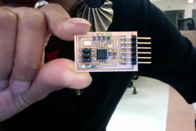
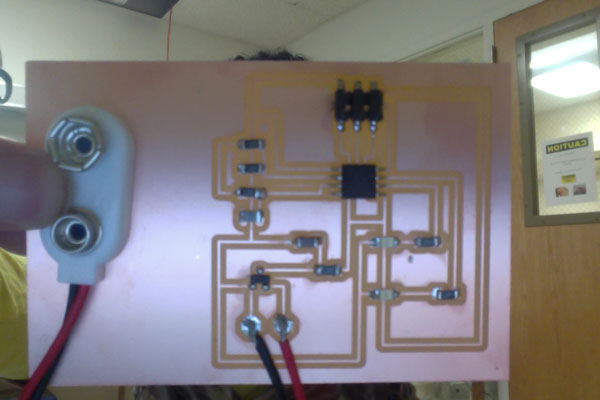
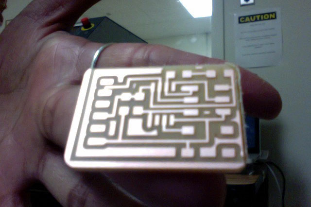
i changed the hello.45.thermistor board to include an LED and resistor.
.png)
After milling out the board i realized that a trace was missing connecting the LED and resistor, so i made an intentional solder bridge to link them.
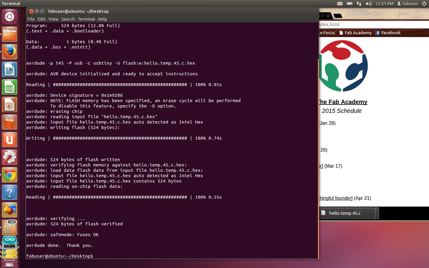
i used the makefile and c file to program the board using the command:
$ make -f thermistor.make program-usbtiny
i got an error "data mismatch" the first time, and then decided to disconnect and reconnect the boards andjust give the command again... SUCCESS!
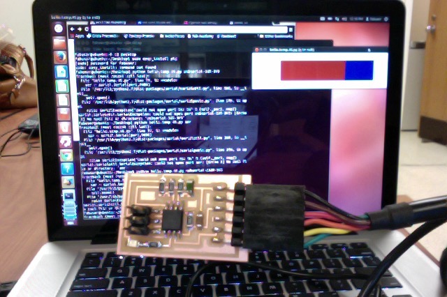
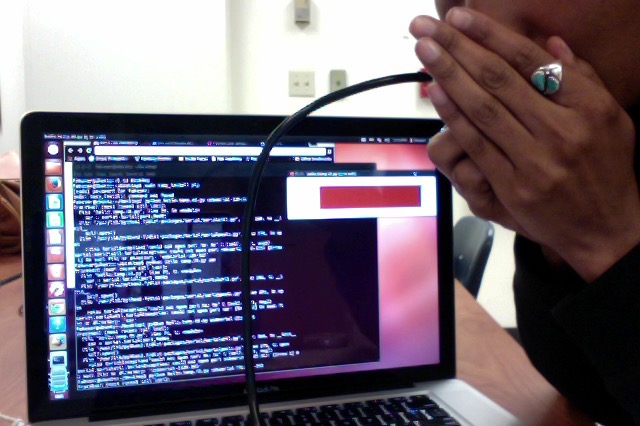
i will come back next week to change the c file to control the light; i want to see my board work!!! now! i looked on several pages to see how to install the python GUI, and after listing the devices, and finding the right device identification number, i used the command:
$ python hello.temp.45.py /dev/ttyUSB0
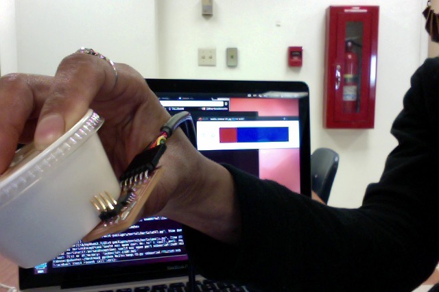
**YAY** it worked!
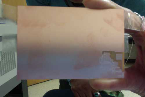
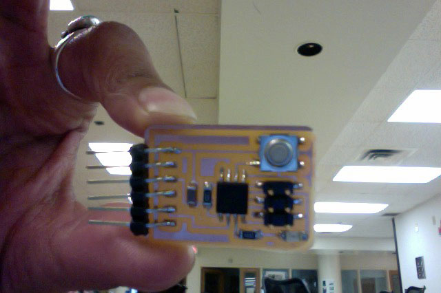
i blew my breath for the heat element to measure (note all red in the pphoto above), and i used a container of frozen sauce for the cold element each held againt the thermistor for a few seconds.
###
Past Week's work on this Assignment Below...
Since i am planning to make an automated heated window seat for my final project, i decided to do an input device that measures temperature. i also thought it would be cool to be able to measure variation. So my thought is a device that would show one light when the air temperature hits 70, and then light 2 LED's when it goes above 76.
Thought process:
It needs a power source, and since i want it to be mobile so we can use a battery instead of a cable. i looked at the example given with the thermistor and noticed SCK pin has 2 connections, wondering what other pins could potentially do this... since the lights will have two different sets of instructions, the LED's will need to be on two different pins. After talking with fabbers i realized i need a regulator for the battery voltage, and that once the attiny is programmed i can re-use those pins, so i think i will put the second LED on the MISO.
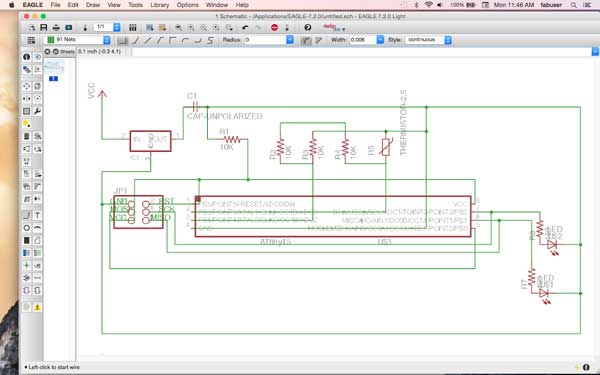
i decided to use Eagle and base the schematic on the info above, and i used some references from previous weeks.
click here for file
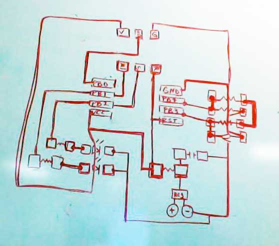
Going from this to the board design is alot easier for me with a dry erase board, and then back to Eagle.
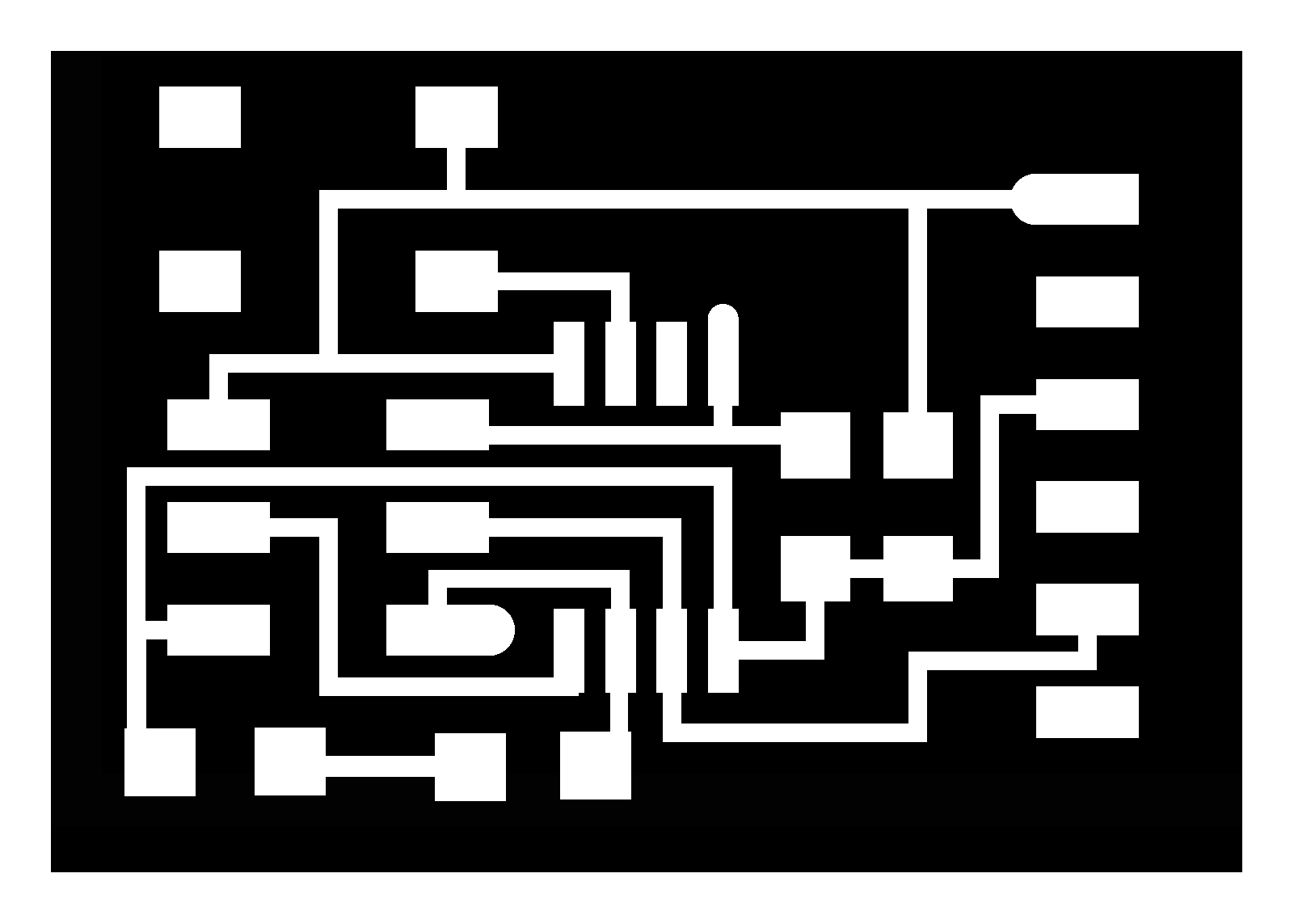
Then i sorted out the components in Eagle, and took the top layer to create the traces for milling.
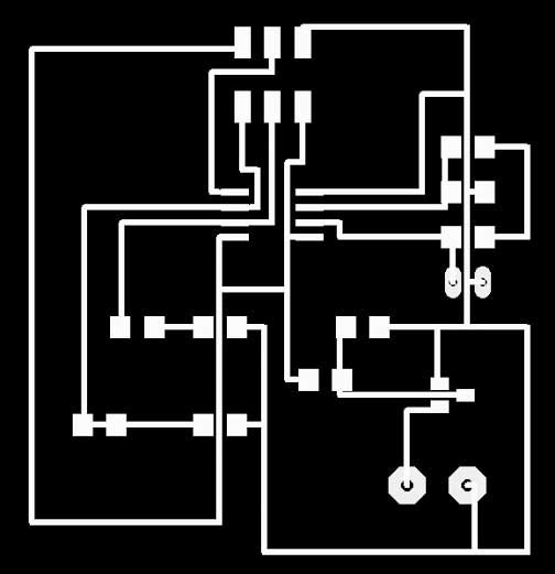
click here for the schematic and board file.
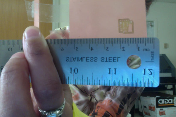
After beginning to mill, i realized the Modela was again resizing my image to be about 1/4 scale of what i input. This board is huge! its about 2in. x 2in. yet what was begun to be milled was only 1/2 in. so i stopped the job, but at this point i had to leave for the day.
to be continued...
...continuing on the following day... i decided to mill out a board that i had done before... back to the helloworld.44... and... half size...
so i am thinking some setting is accidentally set in the machine for 50%... i looked through the Modela manual, checked through all the preferences in the v-panel, scrolled the online FAQ, and then still at a loss, i reached out to the Fab15 class listserve with the question... thanks all for being so responsive and supportive. i realized i was using a fabmodules that was outdated (made for the Modela MDX-20, instead of the MDX-40) and shrunk the .png image resolution by 50%... so i successfully milled out the board after a few hours trying to figure this out.
yet to program it!!
**REVISIT**
so, after looking at how to translate resistance into temperature without a serial out... i decided to do something different, and then come back to this with the networking assignment, as i think that would inform my final project.
i redrew the button board and added a LED, which i will program to come on when the button is pushed.

during programming of this board, i keep getting a message that reads, "error, no separator. done." so i will be back to troubleshoot this in the morning.
BOM
Eagle
milling machine
button board