Design and build a wired &/or wireless network connecting at least two nodes…
For this week I am building a wired serial network using the Hello bridge board and two Hello node boards.
Work flow
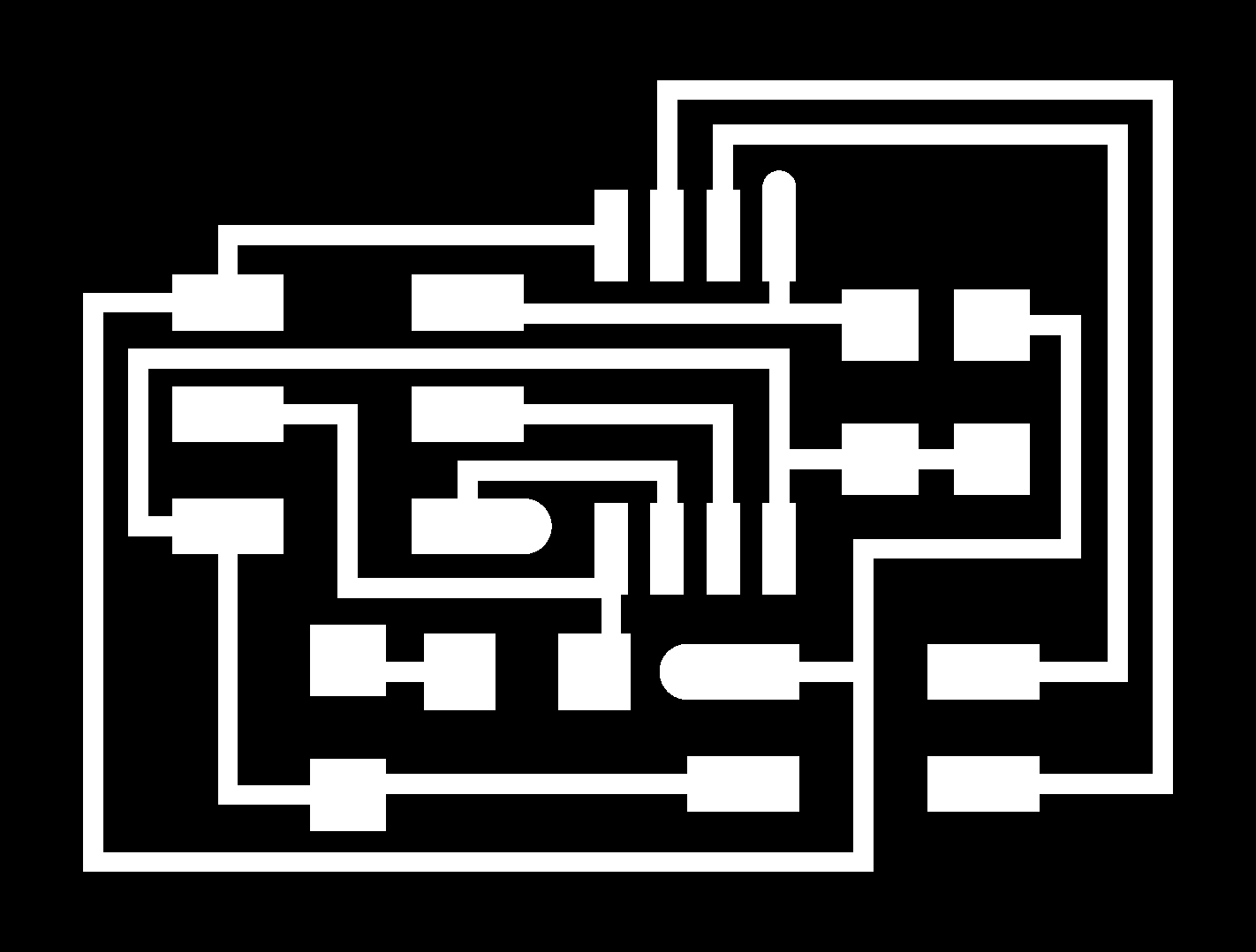
- Download hello.bus.45.bridge.png traces and interior cutout and mill 2 bridge boards. We need only one bridge board, but I want a spare since the Modela time is very hard to come by.
- Download hello.bus.45.bridge.png traces and interior cutout and mill 4 node boards. We will use two nodes and have spares.
- Populate one bridge board and two node boards and solder them up.
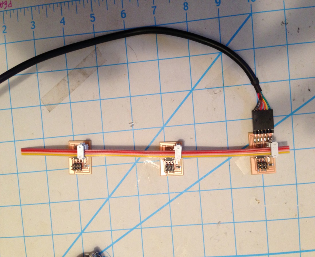
- Connect the boards like as shown here, note that the number "2" labeled board is the FAB ISP. Both the FTDI cable and the FABISP cable are plugged into the same Mac.
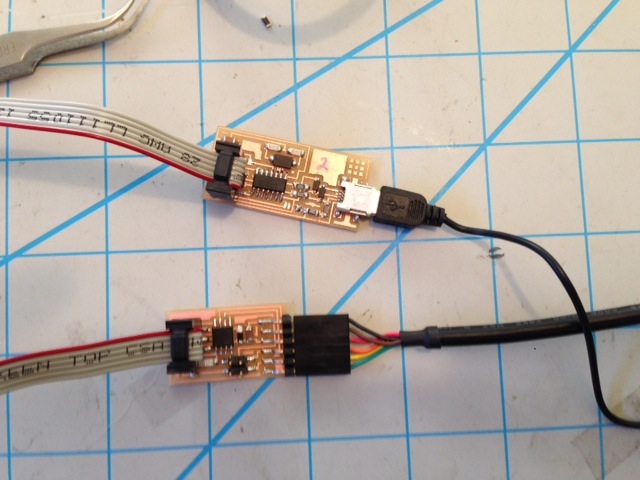 F
F- Flash the boards using this C code file and Makefile.
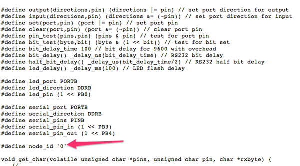
- The default C code is set to have the node ID as 0. The bridge board is technically a node and it can be flashed with the C code unchanged. The subsequent node boards need to have that ID incremented by 1. So we will have Node 0=bridge board, node 1=node board 1, node 2 = node board 2. The C code can be edited in a simple text editor and this is what needs to be changed:
- The populated Node boards:
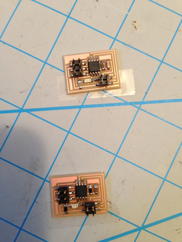
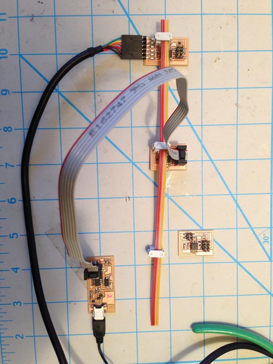
- The node boards will get their power from the bridge board since there is no FTDI header. You will need to delete the .hex and .out file created after each flash then edit the file to change the node and program the next node. Connect your nodes one at a time as in this picture and use your FAB ISP to flash.
- Now you can check your coding and see if everything was done correctly. If not double check your traces and make sure you edited the file correctly. It is a good idea to label the Node boards with a sharpie underneath so you can keep track of the nodes.
- The default C code is set to have the node ID as 0. The bridge board is technically a node and it can be flashed with the C code unchanged. The subsequent node boards need to have that ID incremented by 1. So we will have Node 0=bridge board, node 1=node board 1, node 2 = node board 2. The C code can be edited in a simple text editor and this is what needs to be changed:
- It is now time to check to see if things work.
- Connect the bridge board to your computer via the FTDI cable and connect the boards together with a cable you make like this:
- Open an Arduino IDE and change the port to the FTDI com port. This is most likely the top most port. If you get an error change the port.
- Open the serial monitor from the tools menu and bottom right make sure the baud rate is set to 9600.
- You can now attempt to communicate to the nodes. Type a 1 in and hit enter to send the text to the bridge board. The bridge board will alert the network and all nodes should blink their LED one time followed by a quick blink of the node you selected. You should also get a node identifier message in the serial monitor e.g. type 1 and hit enter results in Node 1 displayed in the serial monitor and each node blinking once followed with the Node 1 blinking again. The default delay is set to 100ms so it is a quick blink. Below is a video of this in action.
- Connect the bridge board to your computer via the FTDI cable and connect the boards together with a cable you make like this:
What I learned
My soldering is becoming much more detailed and thorough. I was able to put together three boards, including picking components, pretty quickly. I checked my solders with a magnifyer glass and had no errors. I also played with the C code and changed the delay and saw how easy it would be to create an interface to interact with a node that had something other than an LED connected.
What I would do differently
I would mill the boards with more complex outputs and perhaps daisy chain some boards off the nodes to carry out independent actions.