
Week 1 - Project Management
Hello World!
San Rafael, California
This is my first entry and it took some time to get here! This project takes me into rich curricular design in an environment of K-8 students and teachers which has ongoing remixing of disciplines, materials and tools. Some call it transdisciplinary learning, others call it project based learning, still others call it inquiry based learning, surely it is all of those blended with the principles of Design Thinking in a classroom where failing rapidly and with low cost is the single most important objective.
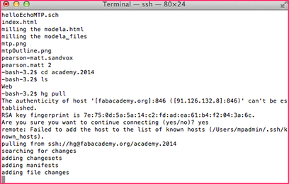
I hope to evolve this web space through my learning and found it appropriate to start with "Hello World!" Mercurial, our primary tool for exchanging data with our primary server hosting this web space, is straightforward for the most part. My laptop admin account would not cooperate and when I created a fresh admin account on the laptop, followed the tutorials, corrected some tutorial typos I was pulling, updating, etc. in under five minutes. Fortunately, my journey took hours of tinkering and diving down many a rabbit hole to uncover the inner workings of Mercurial, the Bash shell, SSH to name a few. I learned many new tools and dusted off my aging UNIX command line skills. I have had a myriad of emails and calls with my mentor all to great learning success! The problem lied on my Mac OSX Lion installation and the permissions, which are still not allowing me to function in the Mercurial environment in my main account, having issues with private and public keys. I continue to try new things and come up with ideas, but that rabbit hole, which I find interesting, must wait. For, in the spirit of pressing onward in this project and in this class we must leave behind some rabbit holes to allow the learning to progress in other areas. Rainy days will come and the rabbit hole will be opened again in the future.
This concludes part 1 of entry 1 using HTML in Nano at the CLI of Bash. Part 2, I am sure, will reveal some inner thoughts and a bit about who I am as I pursue a final project idea that is tied both to education, the Fab Lab, and the Grand Challenges of Engineering. My search unfolds with a deeper understanding of the challenges and a search for a tool to enhance these entries, automate my updates, and ease the use of graphic and video media insertions into this journal of my Fab Academy journey.
[website later updated with Sandvox - see week 2]
mtp
Week 2 - CAD
A busy week to be sure! I am working with a team of two others at the Richmond, CA Fab Lab. This Fab Lab is not there yet and is being brought online as we take the course. We have a temporary electronics bay setup in a portable outside of the main facility which is being setup as well.
I plan on doing more frequent updates, so first some catch up. We have learned how to use a tool called Mercurial to check in and out files in a repository system. This system allows us to work collaboratively while also giving us version control.
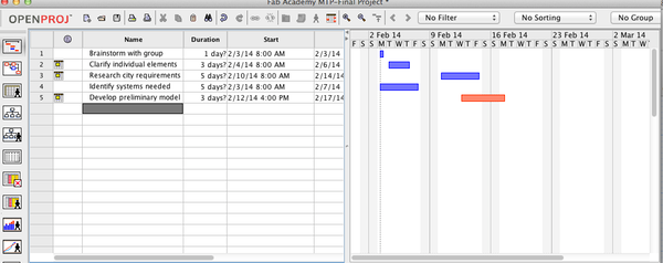
I spent some time with project management software and plan to upload details in the Final Project section. The tool I landed on, at least at spending some more time, is called OpenProj. I will update some gannt charts as I learn the tool.
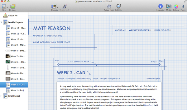
I have been spending some time with the tool I am using to create this site called: Sandvox. It is a very simple and intuitive tool that allows a low learning curve for site design, but depth when desired. I plan on keeping my design slim and nimble. No fancy themes where possible and movies and other renderings offsite.
In week two we were tasked with exploring 2d and 3d tools and to create a 3d model of our project.
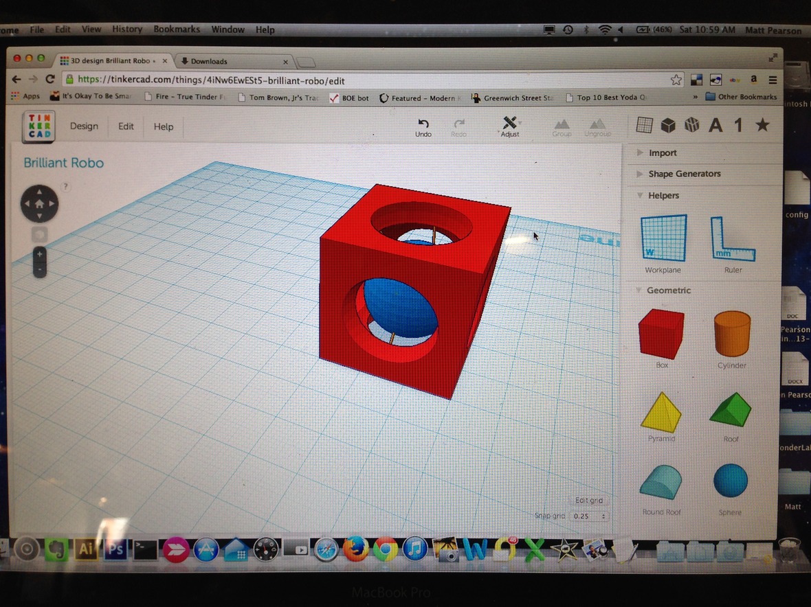
Inkscape (vector drawing), Gimp (bitmap painting) and Tinkercad (3d modeling) all seemed like good tools and all free and readily available. The first tool, and I think the most fun, is Tinkercad. Below is a rendering from Tinkercad using another website called SketchFab to present the model on this site and be able to jump out and manipulate it. Tinkercad is an online modeling program and the coolest feature comes from it being online. All your models are in the cloud and easily manipulatable via any Internet connected computer. I started using this tool with 4th graders and middle school students and love its simplicity. They have great online tools and I just learned yesterday that Autodesk bought them. The model below shows the beginning of our Street Shower project.
Briefly, the shower will function to allow the homeless to take showers. It will feature elements such as photo voltaic power, solar radiation water heating, a bioswale to filter reclaimed water for hydroponics irrigation (possibly Aquaponics if time permits), environmental educational write-ups on the outside, a myriad of sensors to collect data on the Street Showers use, current status, etc. as well as an environmental music system that interacts with the environment for mood music.
You can manipulate the below model if you click on the cube. This version of the shower shows the trailer, tanks underneat the decking, and the beginning of a hollow wall structure that will house a bioswale and hydroponics grow bay. The walls will have transparent and translucent panels to allow users to see the inner workings while maintaining privacy of the shower. On top will be placed a photo voltaic panel to power a low voltage power system to run pumps, electronics and the sound system.
street_shower_v002 from mpearson on Sketchfab.
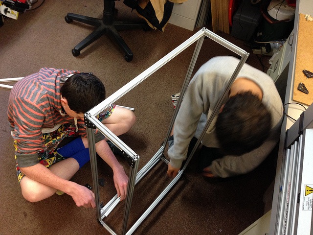
Two of my students and I started prototyping the wall system for the bioswale and hydroponic walls. We made extensive use of the whiteboard to do some rapid prototyping.
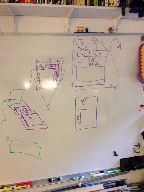
We then took extruded aluminum to create a working prototype to test the bioswale concept as well as the hydroponic concept.
We are looking at a series of drawers for the bioswale each with a different substrate: dirt, sand, gravel, etc. The desire is to have a visual of all elements so a clear polycarbonate drawer is ideal. The design currently has a clear solid panel on the exterior and interior as well as the sides of the drawers. the drawers will be approximately 3.5ft and six inche square. A breakout of this design in CAD is in the works. The hydroponic wall will possibly have PVC pipe that snakes across and down using beer cups to hold individula plants all behind clear polycarbonate interior and exterior walls. The exterior panels of the walls will need to be removable or hinged to gain access for maintenance. In addition, we will have a hydroponic system near the entrance to the shower to allow users to harvest hydroponically grown mint to add fragrance to the interior in a crush (mortar) dish on the wall.
The design will include a low voltage power system driven from a PV panel on the roof. This system will power pumps, microcontroller sensors, and data presentation to the users and those waiting for the shower (schematic in the works)
The exterior of the shower will include documentation on the systems and how they interoperate to provide the shower, hydroponics, and sound system (which is environmental). While users wait for the shower they can learn and interact with the shower. This will help maintain the shower via assisting water recovery, adding energy to the systems, maintenance of the bioswale and hydroponics systems, etc.
The biowswale will function to filter the drain water for the use in the hydroponic system. Shower water will come from a potable water source and will be stored in a tank below the floor. A "Green" water tank will accumulate filtered water from bioswale.

Since we do not have a lab the Fab Academy has set up our group with accounts at the Tech Shop in San Francisco. We toured the facility yesterday and it is amazing. More details here: TechShop SF. The TechShop will allow us access to the machines and tools for future projects. We are scheduled to take the LASER cutter class next week. Our team of three meets at least twice per week for a few hours and will have some build days to start work on the final project, our street shower.
mtp
Week 3 - Computer Controlled Cutting
"Design, make and document a 'press-fit construction kit"
The press fit construction kit is taking shape. Not having ready access to a laser cutter makes things difficult. Iterative design is more my style and I will be enabled in that realm tomorrow when we have 2 two-hour sessions at the TechShop with the laser cutter. This morning at a coffee shop some napkin design happened, you need to always be ready to capture inspiration OR little moments of time left to dream.
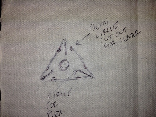
I realize now, that I left out the flex holes at the base of each slot on the triangle vertices. As it turns out, the slot was quite a bit thicker to accommodate the corrugated cardboard used. I used Inkscape to develop the design from the napkin and then imported into Adobe Illustrator (AI).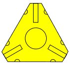
I wanted to make sure the design came up in AI before I started the Laser cutter time at the TechShop. We only get two hours on the cutter and I didn't want to spend it on the initial design. As it turns out, Inkscape is useable, but AI seems more robust. I am new to both tools and feel I should have started in a CAD program and then brought it over to AI. I was able to clone parts for the parametric build, but my design is built off of geometric shapes that should be much easier to specify and input. I started the download and install of the Fab Mod tools and hope to explore those in future weeks.
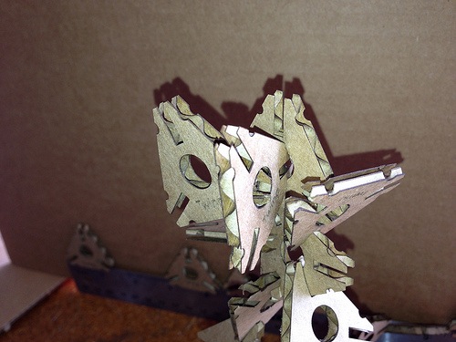
The design has evolved to include pressure points for insertion into the center circle as well as squared tips to allow for stronger “prongs”. I call it a Tring short for Triangle. It came out "Twing" in the wee hours of the night and others overheard me…it stuck.
The Twings may or may not be the only piece. What I would like to include is an articulated system that can have additional pieces constructed under a standardized form ala LEGO style. While LEGO is complex in its scale and ratio system, and difficult to deduce from the user perspective, the LEGO go together intuitively. Intuitive plus a basic system that is easily understood, while both visual and tactile in nature, is the goal.
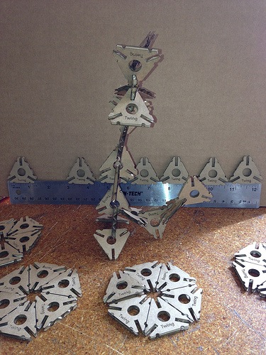
The Twings will allow the build out of a model in four directions, but lacks a system that is structurally strong while also easily fit into our world of rectangles.
Any educational modeling system needs to have both. I hope to try a press board and an acrylic in the weeks ahead when I have time to return to the project.
Work flow
- I started with a sketch that ended up on a napkin in a restaurant.
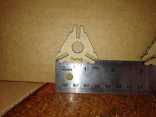
- I took this sketch and modeled it in Adobe Illustrator, a vector based drawing program where the drawing is represented by formulas rather than pixels as in a paint program. My experience with Illustrator is limited, but I worked extensively with Corel Draw 6 years ago and it is similar. Once the learning curve was conquered the initial Twing was born. Six iterations later Twing was ready! Here is the AI file of a Twing: http://bit.ly/1tK3Nh3
- I made the design a quad image so I could printout multiples.
- I needed to take a two hour class at the TechShop to use the Epilog Laser Cutter. I would need to come back to do the cutting of the Twing at a later date. The class was thorough and moved through all the settings, setup and materials you could use. We finished with creating a little dog tag engraving.
- In a few days I reserved the machine to make my cuts. I moved the file to the control machine and realized I should be making a whole lot more than four at a time. The laser cutter is setup as a printer and you send your print directly from Corel Draw using a the settings of the printer driver to control what happens on teh laser cutter. First I needed to setup the machine:
- Use a USB drive to take your finished work to the computer connected to the laser cutter.
- Prepare the computer:
- The computer is normally on and should be left on. Make sure the monitor is also on. If in doubt, reboot the computer to start fresh.
- Prepare the laser cutter:
- Make sure the fan is on. A fire may start if the fan is not running. Never leave the area of the cutter when in operation.
- Turn on the laser cutter. The On/Off switch for the laser cutters is on the left side of the machine.
- Check the lens. A dirty lens can affect your power settings significantly and can also be a source of fire. If dirty, alert the TechShop staff so they may clean it.
- Check the metal bay for debris.
- Set the material in the bed of the laser cutter and set the home position.
- Set the focus by using the metal guide to come down on the material to be cut. This will set the distance and focus.
- Open the project (convert from AI if necessary in Corel Draw) and setup the print and print settings:
- There was not a setting for corrugated cardboard or fiberboard, but there was a set of settings in the documentation for mat board with a 45watt CO2 laser: http://bit.ly/1nTXEBu I started there and used the following settings:
- Speed = 50
- Power = 50
- Frequency = 500
- The above settings turned out to work almost perfect and I landed at a power of 40 with speed and frequence unchanged.
- There was not a setting for corrugated cardboard or fiberboard, but there was a set of settings in the documentation for mat board with a 45watt CO2 laser: http://bit.ly/1nTXEBu I started there and used the following settings:
The Design
The design was planned to be used with cardboard that I had collected from the packaging of laptops. It is corrugated fiberboard with two walls. The same stuff used in packing boxes typically sent in the mail. These particular sheets were neatly cut for laptops and fit nicely in the laser cutters 18"X24" bed. This is the type of cardboard used: http://en.wikipedia.org/wiki/Corrugated_fiberboard
What I learned and would do differently
It was my hope that the cardboard would flex. It does flex, but will not flex more than a few times. The cardboard will also pinch and not retake it's shape. I would like to try using a wood board and/or some tougher acrylic. This will require a thinning of the design so the legs flex.
Week 4 - Electronics Production
For this week we will learn how to fabricate a printed circuit board (PCB) to make a tool used in the programming of micro controllers. This tool is called FabISP. The fabrication of a PCB can be done several ways and I will be using a Roland Modela CNC to mill a PCB "blank."
Unfortunately, access to the equipment is not possible since our lab is in the midst of being created. The lab is in a portable at Kennedy High School in Richmond, CA, and the school is closed for break. Our team of three FabLabers have setup a time with our mentor to go over this week's lesson the following week.
I will continue this entry next week. So that time is not lost, I have moved ahead to week 5 and 3D printing and scanning. You can check that out in the Week 5 entry.
To be continued…
2/28/2014
Yesterday Fab Lab Instructor Mercedes Mane visited us at the temporary Richmond, CA Fab Lab for some much needed instruction for this weeks lesson. We each completed our own FabISP which will be used in future projects.
What we did:
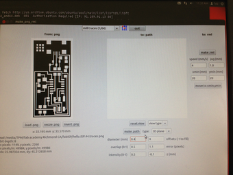
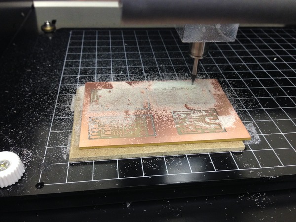
Downloaded and installed the Fab Modules (I used the already configure desktop with Linux). I am in the process of putting them on my laptop. The Fab modules are used to take the boad layout PNG file and convert it for the Modela to mill the board.
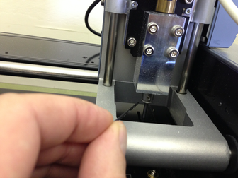
We put a 1/64th bit in and loaded the PNG up and sent it to the Modela. We first had to secure a blank to the milling deck to add a measure of safety so we don't mill it. Then we attached out blank to that with double sided tape.
I read the tutorials and watched the procedure unfold in front of me and noticed slight variations in the instruction. I asked for the process to be shown again and came up with this work flow.
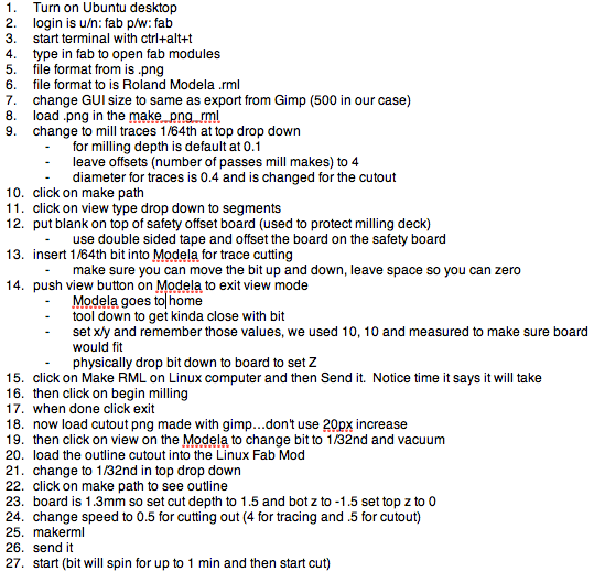
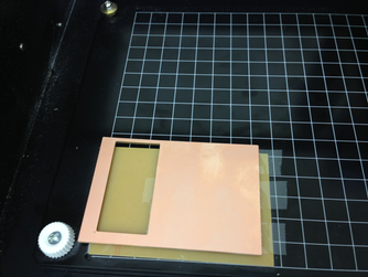
When we sent the file the board milled out the traces. We then changed the bit to 1/32nd and sent the PNG for the outline of the boad for it to be cut. We had to change the depth to accomplish this in the Fab Module.
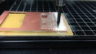
It was now time to pick the parts and solder them in place. I used Neil's trick of using solder wick for the miniscule solder points of the micro USB femail part and it worked great. (Mercedes has some sort of soldering gene…she was pretty amazing!).
We have milled and stuffed the board and now need to program the board with AVR dude. AVR dude We then installed AVR dude to program the FAB ISP.
We followed this work flow (for a Mac):
- Mill the board
- Stuff the board
- Install the AVR dude tools. This is best done by following Lady Ada's tutorial
- Once you have the tools installed you can program the board with another already programmed FABisp. This sounded like a little chicken or the egg came first problem. Fortunately, you can buy boards already done and/or use a friences. We used Mercedes' FABisp.
- Download and unzip the firmware for the board from here
- Open a terminal window and navigate to where you unzipped the firmware
- Make the connections:
- Target FABisp is connected via USB and receiving 5V
- Programming FABisp is connected to the FABisp targe six pin header AND the USB of your computer
- From the directory you unzipped type these commands:
- make clean
- make hex
- make fuse
- make program
- If you receive errors you need to read them it usually comes down to checking the continuity of all your solders. I had a board fail due to a faulty chip that I fried some how.
- To see if things worked you can plug in your FABisp and then check the USB connection under system profiler. You should see an entry for FABisp.
- Remove the 0ohm resistor/solder bridge. This is only there when you program the board.
What I learned:
The FABisp is a fickle device and I know this is not the intention. I made three of these and the first two did not work due to my errors in soldering. I have never soldered surface mount electronics and needed to learn a delicate touch to complete them properly. I also did not understand the logic flow of programming the programmer and then removing a resistor to take the board out of programming mode. I became quite good at dumping solder on pins and then using solder braid to remove the unwanted.
Update: the programming of boards with this FABisp is continued extensively in nearly every week's assignment that involves electronics since the
What I would do differently:
It would be nice to have LEDs indicate whether you connected things properly to the header etc. Building in some feedback for the user to alert them to a backward connected cable etc. might be tough to do given the current design and work needed, but would make it easier for new students to see how things work. This would be a good extra credit tutorial for me to write-up since I built so many of these and tried so many variations of cable connections and computer setups.
Week 5 - 3d Scanning and Printing
This week's material was done during Week 4. Access to resources were not available for Week 4 and you can check that post for more info.
For this week we are tasked with 3D printing a small object that could not be made subtractively as well as 3D scanning an object to make it into a 3D model.

3D Printing
3D printing is called an additive modeling technique unlike a Computer Numerical Control (CNC) machine that uses subtractive modeling. In additive modeling the machine, or artist, adds material to the model to build it up. In subtractive modeling the machine, or artist, subtracts e.g. carves material away from a mass of material.
In review of subtractive modelers, I needed to come up with something where a milling bit (on left) could not access a surface to mill it. Making something hollow seemed without challenge. Making something static also seemed without challenge.
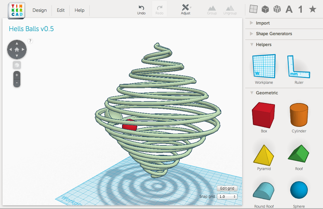
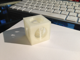
Building off of Week 3 and the theme of toys and puzzles, I have designed a puzzle that can only be made through additive modeling. To be clear, you could assemble the puzzle from parts that were created subtractively, but this puzzle is created in one 3D print and has moving parts. I call it Hells Balls. The puzzle is constructed out of a double helix that is then copied and inverted below itself. This construct creates a cage for the puzzle balls to operate in. The balls will be printed inside the cage. It would probably be sufficent to create just the two double helices, but I wanted to have something fun to engage with, not just look at.
Hells Balls v 0.5 (only one ball)
hells_balls_v05 from mpearson on Sketchfab.
The object of the puzzle is to get two balls into cups at different locations. This version has just one ball and one cup. I am soliciting user input today to see where success lies in a design. Hopefully there will be time to play test and iterate this design. I would like to have easy, medium and hard difficulty and may number the balls and cups to that end. Ideally, colors would be added for the parts so numbers are not needed. The 3D printers I have access to do not easily support multiple colors.
As I dive deeper into design that necessitates parametric capacity, I continue to look for digital tools that are both intuitive, main stream, well documented and supported, and above all else, can output designs that I am after. To that end, I have landed on Autodesk's Inventor. Unfortunately, I am not sufficiently skilled in this tool to use it for this week, nor do I have a PC at home capable of running the software (Inventor requires a Microsoft Windows operating system). While I remedy these shortfalls, I continue my use of Tinkercad to design 3D models. Tinkercad, recently acquired by Autodesk, is far and away the easiest 3D modeler to use in my experience.
Tinkercad is an online tool and no installation is necessary since it runs entirely from a web browser. All models are saved in the cloud, are private or public, easily downloadable in many formats, has tutorials, and is easy to work with. You can also code custom design tools and/or build off of other custom design tools. I started with a helix tool and then modifed the parameters to stretch. My goal was to create a sphere and as you can see, there is work to be done. Click on image to enlarge.
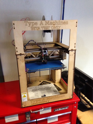
March 1, 2014 - Update from the 3D printing trenches at TechShop San Francisco.
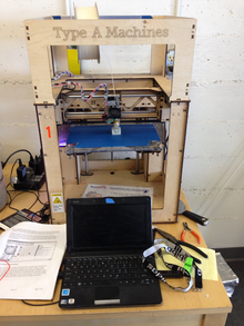
Since the Richmond Fab Lab is still coming online we are doing much of our work at the TechShop in SF. Our 3D Printer choices are the MakerBot and a machine called the Type A. The Type A came highly recommended and there are two at the TechShop. I went with the Type A. The machine on their website is the newer one. The version I used is on the left. The printer is very similar to the Makerbot, but manipulates the Z axis by moving the printing deck. It also has a very good printhead and filament feed system. The print deck is not heated, but since I am using PLA that was not a problem. After spending time with the Printrbot and the original Makerbot, this machine is golden.
I decided to design an alternate creation than the one above as Hells Balls would have taken all night to print and would have been tough to iterate given my limited knowledge of the printer. I decided to create a box with a sphere inside. This design also included cut outs on each side. I used TinkerCad to design this in about ten minutes.
Create in TinkerCad, then download the STL file and put it on a thumb drive. Now, it is off to the very small sub-notebook that is hooked up to the Type A.On this small computer we have the two pieces of software necessary to create the piece: Pronterface and Keep It Simple Slicer aka KISSlicer. Pronterface controls ther printer and KISSlicer takes the STL file from TinkerCad and creates the GCODE file you feed into Pronterface.
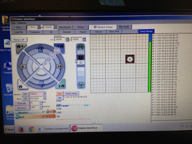
Picture of Pronterface to the left. This tool allows you to control the printhead, zero to a home position, set temperatures and more. This is the same tool that the Printrbot used when I built that although the version I had caused quite a bit of cutting edge bleeding if you know what I mean.
KISSlicer makes a GCODE file of the small piece I will refer to as BoxBall.
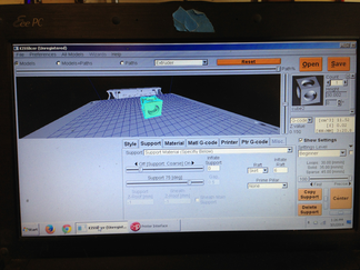
Ok, time to print! Unfortunately, the first print did not have adequate infill or a raft to build pillar supports for the ball that was suspended inside the box. What does all that mean? Infill is how solid the piece is. KISSlicer can put air pockets inside to save both time and material. It works great when you have the right amount. A raft is a little later of plastic, like a raft in the water, to build upon. This allows layers of plastic to adhere more easily. In my first try, KISSlicer made a pillar to support the floating ball. It was working great till the printhead tipped it over on its side. In the second attempt, I added a raft in TinkerCad and increased the infill from 33.3% to 50%. As you can see, the arches of the side cutouts were given a pillar to support them. This was done because I had enabled this option in KISSlicer.
Box Ball final print with movies below.
3D scanning was an adventure into Autodesk's 123D Catch. I loaded the application on to my iPhone 5 and searched for something to scan. This application is free and relies on a server farm to process images you feed it from your phone. The process can take from minutes to hours and is a quick way to get some interesting results. It should be noted that this system can be inaccurate in the details, but gives some amazing and startling captures. The application walks you through the process and uses the phones sensors to detect which orientations you need and are on as you circle the subject. I used about 35 photos for this dragon.


Step 1: Start a scan. The software is becoming more and more social as it incorporates other users scans and an interface for you to share your scans.
Step 2: Take a series of pictures as you circle the subject. The subject should be uniformly lit and have a contrasting background. In this picture you can see that I do not have a contrasting background. I added white paper all over the place in a subsequent attempt.
Step 3: Review your photos and delete or retake any that did not work out. It is unclear to me what qualifies as a bad shot other than poor lighting or angle.
Step 4: Then submit your photos to the server farm and await your results!
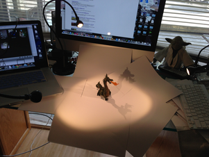
Here is my "stage" for taking the dragon photos. Quick and dirty and Yoda did not bother me.
Here are two scans, the dragon and my hand. Pretty cool stuff!
Dragon
The Dragon bombed…not sure what went wrong. It blended the entire stage. I think placing the dragon on an outside table in the sun would be better…at noon! Wait! As it turns out…there is lots of scatter pickup from the paper "stage" and i was looking at it from the bottom. Ta da! You will have to maneuver the model to flip it over if you click on the 3D manipulate box.
Handy Tools
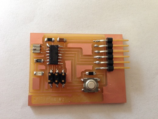
Week 6 -- Electronics Design

This week...
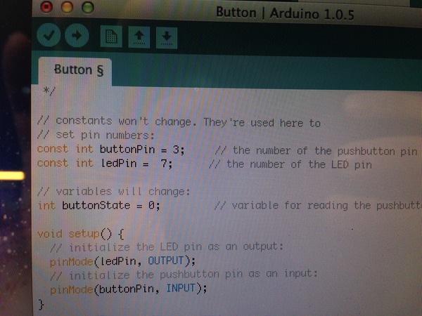
This week we have been assigned to tweak the design of the Hello-World board by adding an input and an output. We will then use this board to learn how to program in week 8.

To do this we need to learn the following:
- How to use the Eagle PCB Design Software. This software allows us to create and mill printed circuit boards (PCB). We will use this to add components and recreate the trace routes on the board.
- How to take the output Eagle file and use Gimp (or another paint program) to prepare a cut file for the board.
- How to use the Fab Modules, and a little bit of Linux command line and Ubuntu, to create the path files to mill the traces.
- Send the path file from the Fab Module to the Modela milling machine to machine a blank copper board.
- Once we get the board it is time to load it up and solder in the surface mount components.
My learning begins...
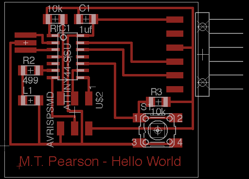
The Eagle software has a straightforward GUI and for me is intuitive. The interface updates two different displays: schematic and board layout. The schematic view is an easier to design interface since you can label and do virtual connections. Each electrical connection that needs to be made from one point to another will need to have a physical path to follow on the board which is displayed in the boad layout view. The board layout is what gets milled on the Modela.
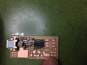
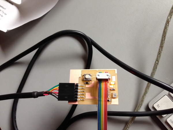
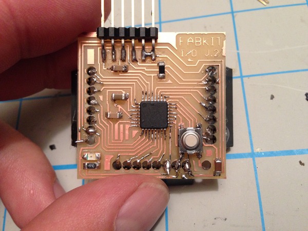
I decided to keep things simple since this is my first exposure to all of these tools. I added a button (input) and an LED (output). Here is my final schematic followed by the board layout:
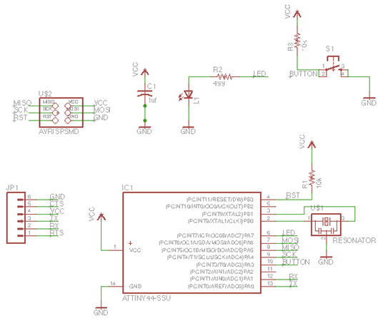
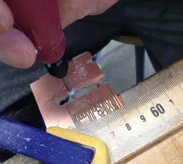
After starting the soldering, we realized we do not have the correct resonator and have ordered the part: ECS-CR2-20.00-B-TR. Available at Digikey here. When this part arrives we will add it to our board and I will upload a picture of the finished board. Below you will find my raw step-by-step for taking the file to the Fab Module and milling with the Modela. Below tha are some pictures of failure and an attempt to hand mill. While I did get a workable "Frankenstein" board, I decided to remill the board. The first time around we did not invert the cut file to have it properly cut the board.
My raw step-by-step…
Some pictures of the milling (failed version)…
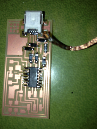
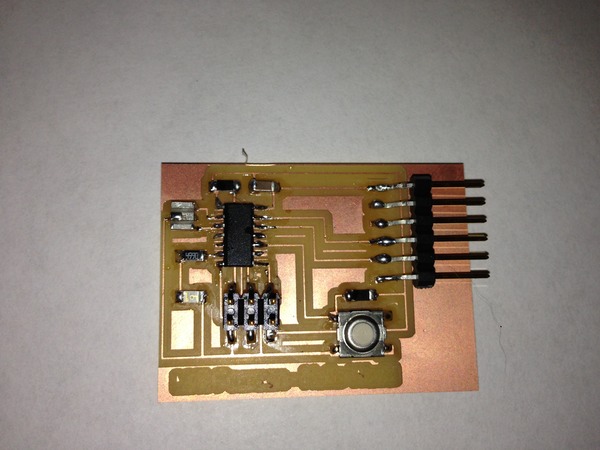
Update 3/28/2014
The order of resonators arrived and the board is now complete and ready for programming in week 8. I will put a picture here of the completed board soon. The resonators showed up and here is the completed board. I need to adjust the title of the board done in Eagle which ws too fine to come out properly. I will adjust in
What I learned:
Programming with the FABisp took me well over 75 attempts and it ended up being the computer I was using and a problem with USB 3.0 apparently. When I installed all the tools for the third time on an older Mac things worked the first time. I had also assumed that the green wire was ground when connecting as in houses, but it is infact the black wire. I knew this, but overlooked it in my repeated connections.
What I would do differently:
I arranged things manually in Eagle and created a name plate on the bottom. As you can see, it did not come out and needs to be done in thicker lines manually using Gimp or another paint program. I also don't like the extra copper all over the place, but it saves time to not have to remove it. I like thicker traces and easier to see connections.
Week 7 - Computer Controlled Machining
Make Something Big!
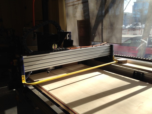
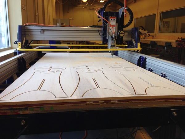
This week we were charged with making something big. Big being a relative term, I decided to interpret that as the size of a piece of furniture. I will make some bar stools on the ShopBot. The ShopBot (at right) is as big as a small car and likes to work with sheets of plywood or similar dimensioned material. I first had to schedule a 3 hour class at the TechShop to use the tool. This was tough, but finally found a class in San Jose, CA (2 hours away). I decided to book the ShopBot for right after the class in San Jose, since the SF TechShop was tied up until early April. I guess Silicon valley likes working with small stuff and not big stuff, the ShopBot there is wide open for scheduling!
The work flow for my design is as follows:
- Come up with a low resolution prototype in a tool I am familiar with: I sketched it on paper. Low resolution means, very little of my time from concept to version 0.01 of the idea.
- Now that I have the idea, formalize it a bit more and do some research on stools. What are the standard heights etc. These stools need to fit under a bar height counter. What is bar height, what is the height of a bar stool etc.
- Search for examples. ShopBot's website has some great designs to serve as examples. My design was created by taking an existing design and tweaking it to my needs. This design was tweaked using ShopBot's software PartWorks directly. Partworks is a very straightforward tool which is used to take a design and create the path files necessary for the ShopBot to make it's cuts. The design could have been created in many tools including Inkscape and Adobe Illustrator, AutoDesk Inventor, etc.
ShopBot's Partworks Software in Action
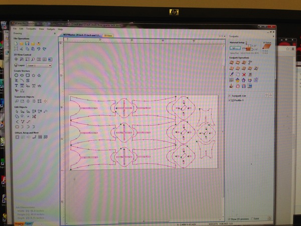
Partworks is a fairly intuitive tool and with the mouse over help I was well on my way. The creation of the paths was a click away. I resized the stools to take into account the thickness of the plywood and also increased their height and changed their edge look a bit.
The ShopBot Tool Interface Software
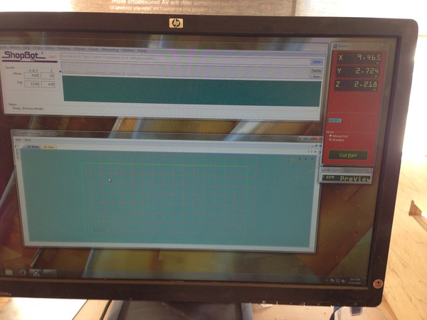
Used to calibrate the X-Y-Z. This will also set the speed of the mill etc. There is quite a bit more to this tool that I would like to learn.
Loading the Plywood
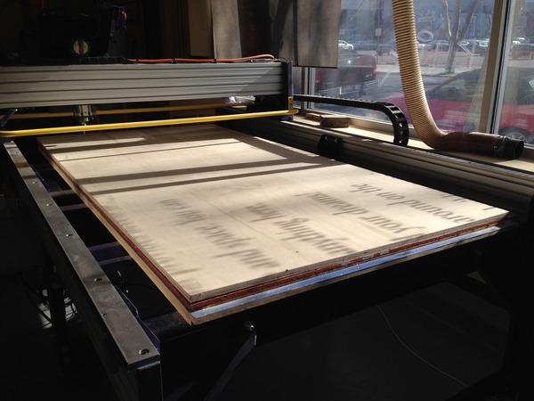
I set the plywood with brass screws onto the cutting surface. There were two sacrificial boards in place so I felt comfortable moving forward and leaving them there to protect the machines surface. This turned out to be a mistake. The boards were old and warped slightly which gave me an uneven surface. We use brass since it is a soft metal the will be more gentle on the end mill if I accidentally cut into them. I used a screw in each corner and on the long sides in the middle. Next time, I will use more screws and put in my own sacrificial board.
The Cut Begins...
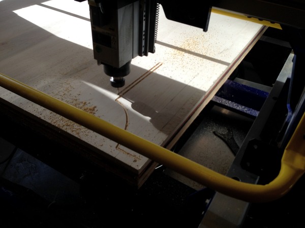
Mesmerizing. Looks very good on top. On the bottom, I should have used more screws and had it penetrate further. The tool interface sends out a warning about depth of cut, but now I know it is ok to go a few extra hundreths of an inch, or even more, to get a good finish on both sides.
The Cut Continues...
Assembly of the Stools
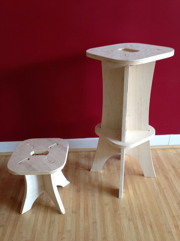
Since the ShopBot did not fully penetrate the material in all locations due to uneven surfaces, the assembly required some sanding and filing to get the slots to be the right thickness. Once this was done the pieces came together nicely! I am considering a new stool design and also seeing how the Twing from an earlier week might come out at a large scale.
Week 8 - Embedded Programming
Program the Hello World Board from Week 6
(and read the data sheet for the ATtiny44)
In this weeks video conference with the world we learned about the steps necessary to program a micro controller. I also learned some bad news, some good news and later some quite enlightening elements of micro controllers.
The Bad News…
I would not be allowed to buy an Arduino and program it for use in my final project. I am planning on a visual artistic representation of live environmental phenomena: Photo voltaic electricity generation, UV index, humidity, temperature, time, ambient pressure, and possibly ambient sound via decibels.
The Good News…
I would be allowed to build from scratch an Arduino and program it for use in my final project. Is this good news?
The Enlightening Learning…
This will play out more below in the steps I took to program the Hello World board. However, by diving into the white paper, playing with the Eagle software to design a board, and having learned how to fabricate the actual PCB, I have decided I do not need an Arduino. I will not make an Arduino. I will make a board that is far simpler and directly catered to my final project. Simpler, more efficient, costs less, and to be integrated into the visual artistic expression, not hidden in a box.
And the Programming Begins…or not…
What should be a straightforward connect it an program it turns into an epic journey down a rabbit hole. I am using the Arduino IDE to program my board using a straightforward set of tools. Unfortunately, installing the tools was the easy part! I installed and configure the following for this week's mission:
- The Arduino IDE Software e
- The ATtiny Board Files
- The FTDI Drivers
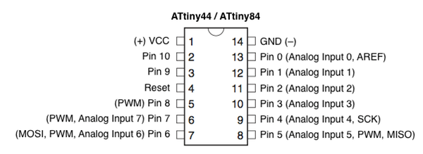
- I also needed to study the data sheet for the ATtiny44
- Since I am using the Arduino IDE to program with for the moment I need this cheat sheet for the pins:
Once the IDE environment is setup you can proceed to burning the boot loader and then programming the board. You are not actually burning anything to the chip, bu this sets the fuse bits of the chip to run at 8MHz. I followed this tutorial to make all this happen: http://academy.cba.mit.edu/content/tutorials/akf/embedded_programming_arduinoIDE.html
And now, what did not work…
I tested the boards by toning them out and looking closely at all solder joints. Everything seems good. I kept getting this error:
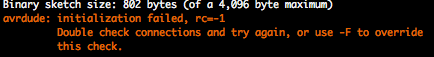
This error traces back to a bad connection, an incomplete solder joint, or something plugged in backwards. I once again test and test and test with a DMM the connections. Everything is fine. At some point I think I brick my chip on my programmer as it no longer will come up in System Information on my mac…
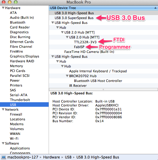
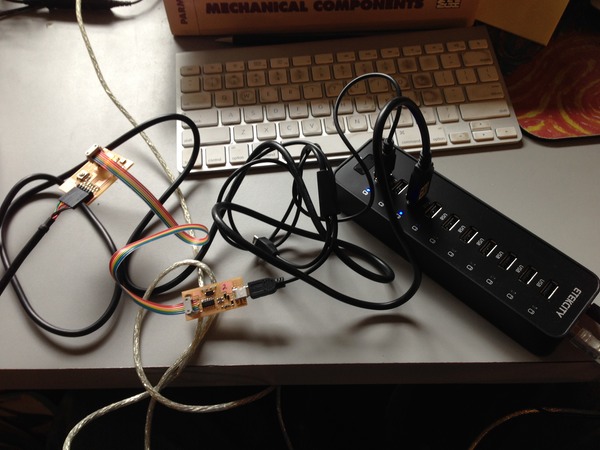
See below my final resolution, using a USB 2.0 external hub. My programmer, and the FTDI cable, will appear under the USB 3.0 bus, but it will give the above error. I only figured this out after bricking one chip, soldering in a new one, desoldering and soldering jumpers, looking for ages for forums and trying to reflow lots of solder joints. This shot below if of system information: click on the Apple in the top left of your OSX desktop and select about this mac, then more info. You will need to click on the below menu to pick USB.
Before I figured out it was the USB 3.0, at least in my case, I found a bad solder joint that had slipped by me. This chip is 8mm long. Notice the foot underneath the blob.
This second foot from the left of the ATtiny44 was soldered on top and when I toned it I would push down on the foot to make contact…then release and it would lose contact. Only I did not know this, till it occured to me it could happen. I looked close and sure enough when toned from the top of the foot it did not show a connection. Lesson learned, but I still got the same error.
I finally found a forum where a user had tried moving away from USB 3.0 and without a hub had to put the project on hold. Immediately upon trying a USB 2.0 hub it worked on the first try!
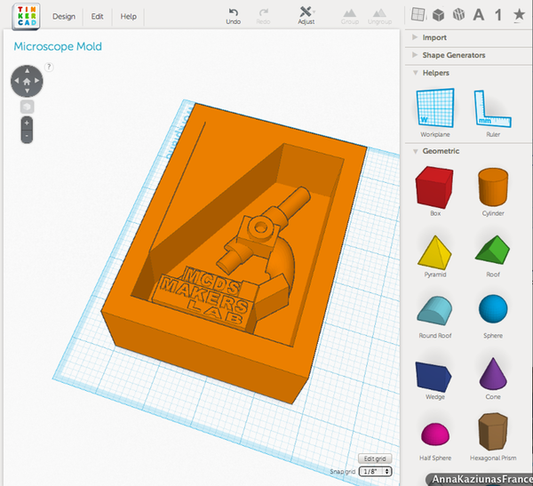
Week 9 - Molding and Casting
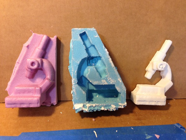
"Design a 3D mold, machine it, and cast parts from it"
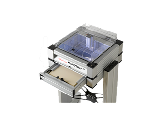
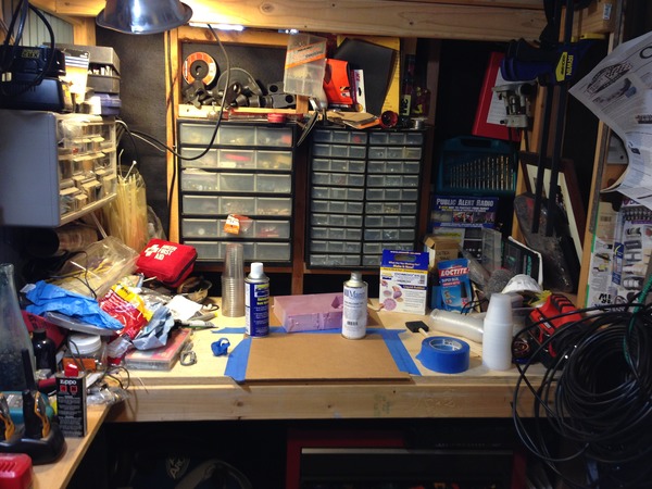
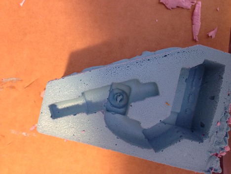
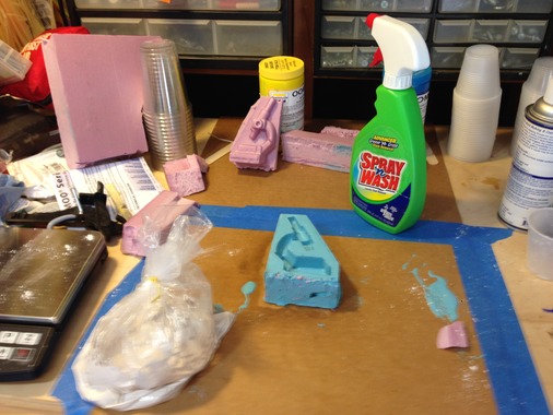
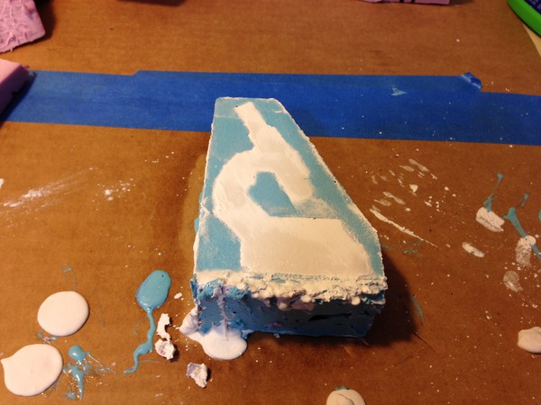
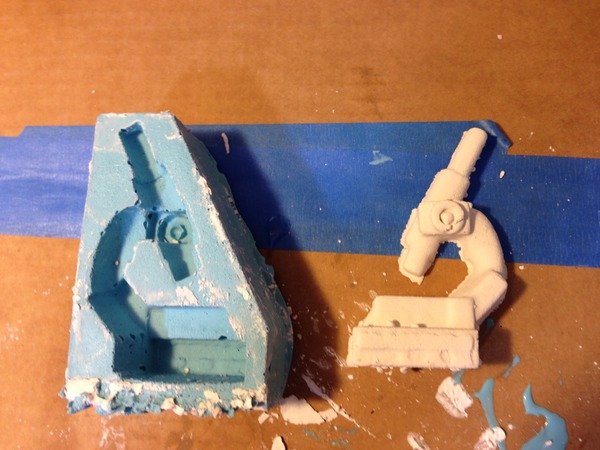
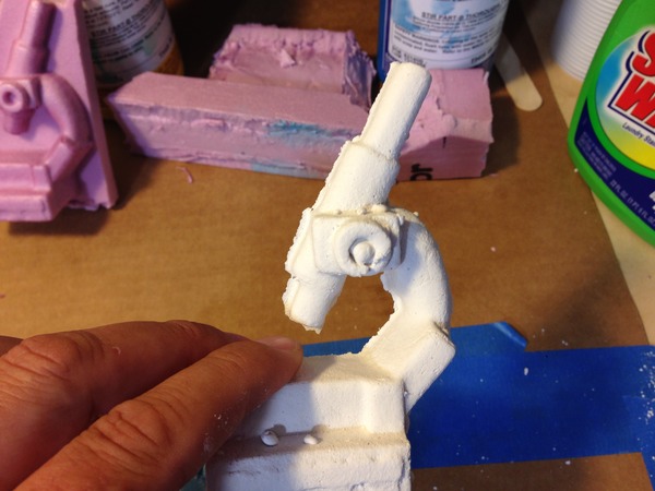
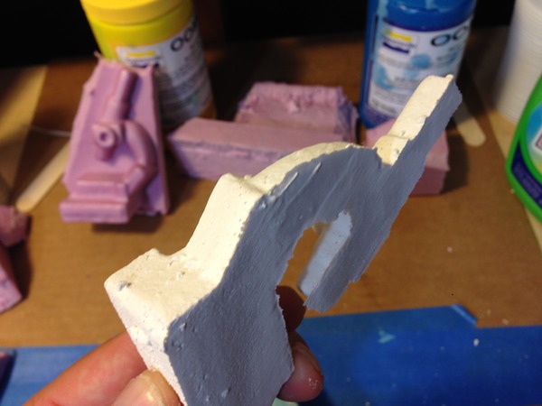
Well ok then! Steps 1 and 2 were done with Tinkercad and the 2Bot respectively. I cover Tinkercad during week 5 and 3D printing here. The 2Bot is a neat milling machine for Expanded Polystyrene (EPS), higher density foams, machinst wax and I am doing research with mushroom foam.
Tinkercad and the 3D mold
The 2Bot uses a tray that suspends the material in two tension clamps held right and left. It defines the Z top by calculating the middle of the clamps less one half of the height of the material. Not an ideal situation as no "bit drop" z calibration is available. I am sure this is to keep things simple, but results in errors. It does allow you to flip the material for two sided cutting as well as scaling the model to any size you want by calculating the material needed. This is all done in software. All path calcs are also done in software.
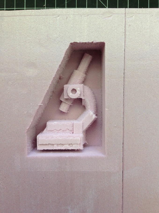
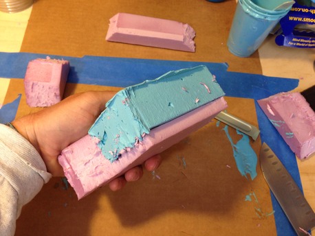
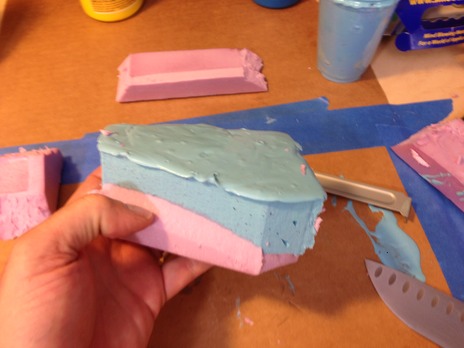
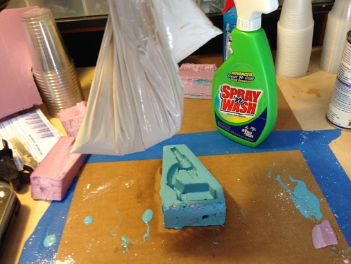
The model machined really well, but I left it a bit tight on the bottom. You can also notice all the little "hairs" hanging off of everything. This was done at a resolution of 0.01" with a 1/8" bit. I am uncertain how the 2Bot will handle a different bit as it is a unique design.
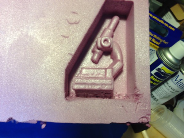
As you can see in the below picture, after applying a little heat with a heat gun the "hairs" melted and the surface became more sealed. You can also see where i manually expanded the bottom of the mold. I learned that if you do a two-sided cut (a small checkbox in the 2Bot software) it will ask you to flip the model to do the opposite side. I did not need the other side cut and did not want it to cut out the mold (see model above in TinkerCad). If you select two sided and never flip it will not cut it out.
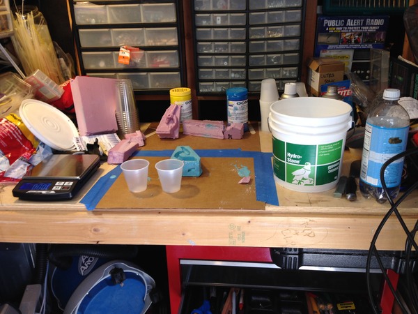
Getting the work area ready...
- Prep area on table:
- Oomoo 25
- Mixing cups
- Gloves
- Protect work surface
- Face mask
- Demolding release agent
- Mold (EPS microscope)
- Mixing sticks
- Since I am working outside and there is a breeze, move mold inside on cardboard after pour (pour inside?)
- I may move the whole operation inside as the wind is annoying and may impact the pour.
- Mix the Oomoo part A and part B by hand in containers with a "square" edged device per tech video
- Measure out into cups in equal parts and mix a bit more
- Combine cups into one or the other and mix some more
- Pour mixed oomoo into another clean cup
- Pour into mold in very fine stream very slow and let it level itself out (this is where the wind will mess stuff up).
- Oomoo 25 sets in 75 minutes and Oomoo 30 sets in 6 hours. I will use Oomoo 25 first to see how it goes.
- Demold after 75 minutes
- All of this is at ~73 degrees Farenheit
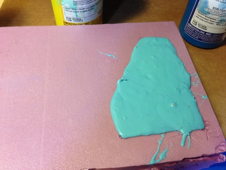
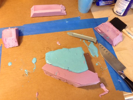
For Oomoo 25 I will not use the vacuum chamber. Hopefully I can recast the positive if there are lots of bubbles. I spoke to Smooth On Tech services and they said it should be fine except that the Oomoo 25 will creep into the little holes in the EPS. I have applied heat to the surface which has melted and sealed the positive, but it is still rough. I also did not make the mold big enough along the bottom of the microscope and carved it out by hand resulting in a rough top. Hopefully this will not impact the actual negative. I will also use mold release agent per technician's recommendation…here we go!
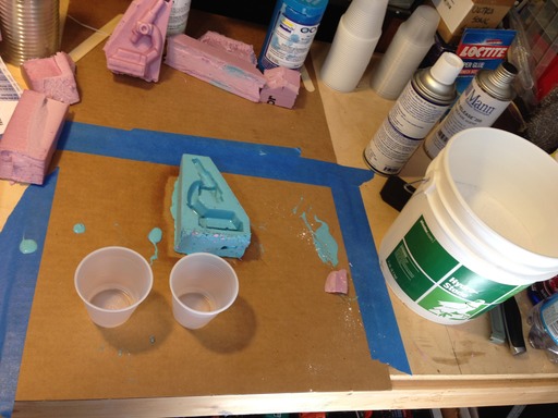
So, all setup and ready to go in my small workshop. I decided to clear it out and get a windless area to pour. Good idea as the wind picked up! I did not have the recommended square steel stirrers as in the Smooth on videos and used wooden tongue depressors that the lab had. While cleanup will be a pain with the metal stirrers I can see whay they recommend them. The viscosity was very stiff at first and required quite a bit of careful stiring. I was right at the edge of the temperature guidelines and maybe a bit under. As I poured the Oomoo it became clear I was fighting a 15 minute window, again perhaps due to the temperature. It came out in ribbons. I was concerned I would not have enough, but it turned out to be the perfect amount. Once I was done pouring I tapped the sides and bottom to release bubbles. I didn't think any would come out in the thick liquid, but sure enough they started rising to the surface. Now the 75 minute clock is ticking which I will probaby extend to 90 minutes. Since I am doing this at home, and do not have easy access to the lab and milling machines I hope this works out. While I wait I am starting a composite bowl in week 11.
Releasing the Oomoo from the mold…
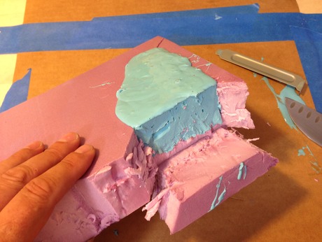
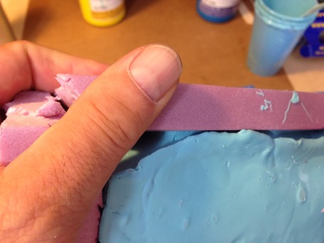
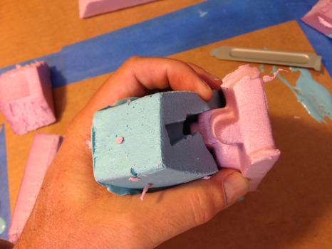
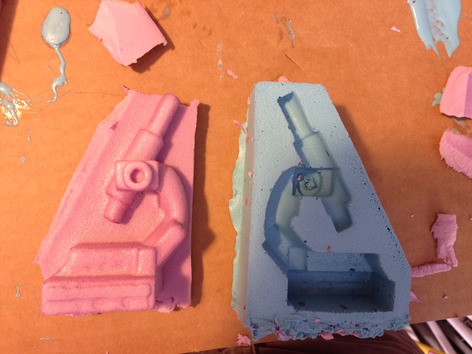
It was rather difficult to get the Oomoo out. I ended up carefully cutting the sides of the mold. The Oomoo was very sticky even though it cured for 90 minutes. In the end, I was able to carefully release the mold and retain the positive, albeit without the walls. There are many bubbles and next time I will use steel stirers as well as a shallow mixing container. I used plastic cups the Lab had and it was challenging.
And on to Hydrostone…
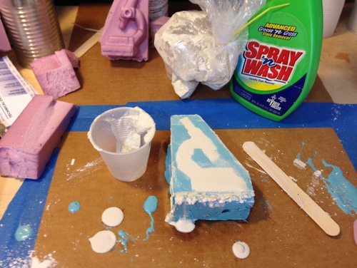
I read up on this plaster/cement stuff and found a great video on technique. I decided to try out using soapy water in the mold to release and reduce air bubbles in the hydrostone. I did also pre spray the Smooth On mold release. I also decided to mix in the plastic bag as in the video. I carefully weighed 100 parts Hydrostone to 32 parts water and ended up mixing 300 grams of the Hydrostone. It seemed to come out a little thick but filled in the mold nicely. I then scraped off the surface to get it flush with the top. I think in a future casting I will build a border so it can be hung on the wall. I am waiting for the Hydrostone to set to see the results.
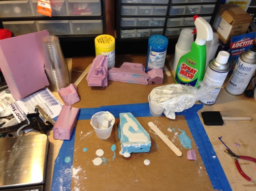
Note that the Spray n' Wash is not that, I am using that bottle to hold soapy water made with a generous helping of dish soap.
Wow! Demolding a success!
I had no idea things went so quick with the Hydrostone. I remember Neil saying it is quick, you don't have to wait over night etc. etc. Upon digging and some research I learned it sets enough to demold in just 30 minutes! This entire process went slowly for me, on purpose, so that I didn't miss a step.
I scraped the edges of the final casting with some aluminum scrap and am quite impressed. No bubbles evident I guess as a result to the soapy water.
Some things I would do differently next time:
- The EPS seemed to work fine and is very quick to mill. I will give more clearance to the edges and possibly apply Styrospray 1000 to the EPS before making the silicone mold. This will give it a very smooth finish, but adds a step.
- I would like to mill something with the wax.
- The Oomoo needs a better stirer than a tongue depressed and a shallow bowl. This will help with the bubbles.
- I would change nothing with the Hydrostone…the soapy water and the bag mixing is the way to go!
Week 10 - Input Devices
"Measure something: add a sensor to a microcontroller board that you've designed and read it."
This particular week's assignment was extremely challenging. The FABisp worked only once out of dozens and dozens attempts with the Hello World button and LED in Week 8. I suspected I had issues. Yes, I did! Try as I might, I could not issolate the fabled -1 error with AVRdude. This particular error coudl be due to all sorts of issues:
- Soldering errors
- Component selection errors
- Traces gone awry or peeled off
- Cables miss wired or plugged in backwards
- Bad ISP
- Computer setup and drivers
On and on the list went with no clarity other than to check and recheck everything. I redid boards over and over to no avail. I have very limited access to the lab and the Modela to mill boards, so when I go in there I tend to mill a bunch. In the beginning I had errors in milling and had to wait a week to get back in to the lab. Now, I am quite good at milling and designing the boards. I have made so many of the Hello boards I found it hard to continue with no joy. Yes, I got good at the soldering and the milling, but I just wanted the lights to blink and the sensors to work!
I read in one forum, I visited dozens, that the USB 3 interface might be causing problems. I tried a USB hub. Nothing worked! I did get the FABisp to show up in my Macs system information.
And then, I tried a new computer! Yes! When I typed in the make command at the command prompt and it worked my jaw dropped. Yes, a simple little thing like this was jaw dropping. I didn't know how to feel and then it I screamed. So, here are some pictures and notes about this journey…
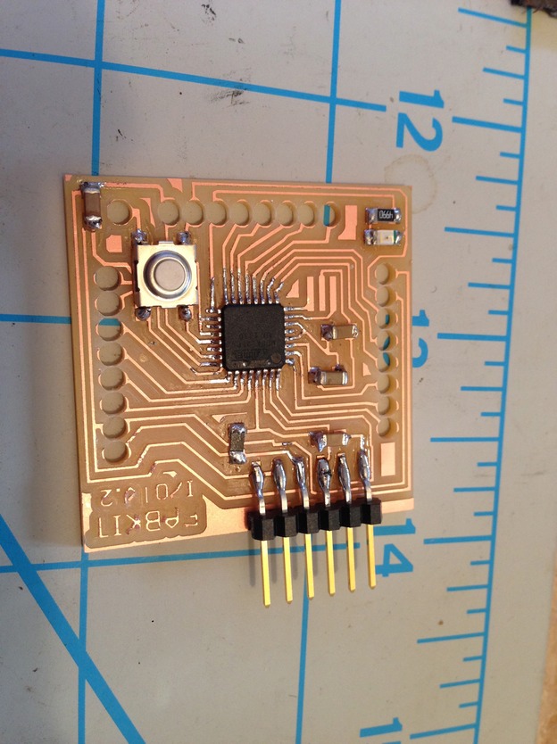
The Fabduino
With failure at every turn I decided to use the Arduino IDE to develop inputs, outputs and networking for three weeks of catch up. I also decided in this route of the Fabduino board so that I could use this learning in my final project. I milled two boards because I knew the networking week was coming up. Unfortunately, I messed up on the milling and did not invert the colors and ended up with little donuts cut out for my female headers to be attached to. I was determined to make them work because I would not be able to get back into mill them again for a week and could not fall behind even further. I was behind due to a teaching adventure in the Mojave desert with 7th graders (another story altogether).
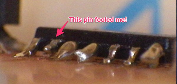
Here are the boards I milled with donuts (oversized holes) cut out instead of the smaller holes. I didn't know I had holes that were too big until I had already soldereding on the components on both boards. I did this because there were no female headers in the lab and I ordered them. The error of my ways became more apparent when they showed up. What to do??
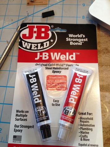
What if I glued the headers in and tilted them toward the contacts? Lets give it a try with some high temp JB weld so they can handle the solder. Sadly, I aborted quite quickly as the goopy epoxy was too messy and I could not sit there an hold things for an hour…I needed something else. The first thing that came acoss my mind was hot glue. I would have to wait to get a glue gone from my school.
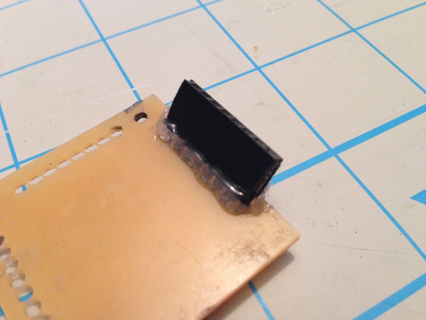
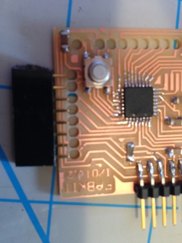
The hot glue did the trick and dried quickly. I was able to angle the headers toward the now very small landing pads they were to be soldered to.
Below is a finished board. Unfortunately, I did not yet have my breakthrough with AVRdude and things continued to fail at this point.
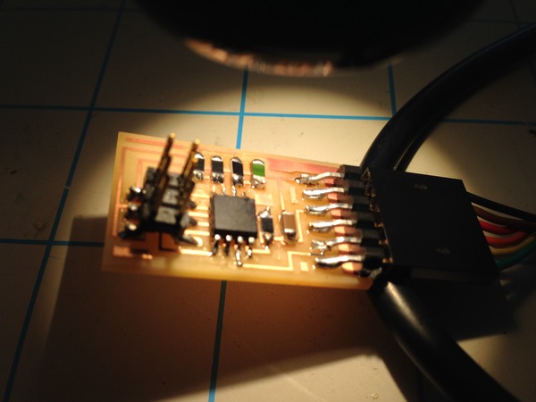
I moved on (after hours and days and weeks of trying things, due to my time being spread out and acccess to labs being tight) to a simple temperature board next. To get these boards, I became a little board factory and milled lots of options.
The finished temperature board…
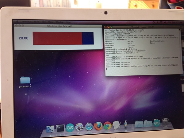
It was at this point that nothing worked and I decided to start over with an older Mac laptop running OSX 10.6.5. It had older USB ports and was a clean install of the OS. I went through the process of installing the drivers, Crosspak, etc. I hooked things up and it failed. I looked closely at the connections and everything seemed fine. I then decided to doublecheck all pins (schematic and continuity), check for shorts, check for screw ups. I had always thought that green was ground and discovered that the FTDI cable had been installed backwards. I flipped it around (how long had I dont this for?) and tried again. Failure. I then flipped the FABisp connector as I always flip all the cables and play with the pinouts. Success! Right after I emailed my instructor…success! My jaw dropped. FInally, I could play with the program, but first just had to get it to display the temp! Here is the temperature…yay!
What I learned:
When things work and you can perform real tasks with a tool you created it is a great feeling. I learned that no matter the detail, it cannot be overlooked. Checking everything and having it pass muster leaves only what is left that could be the problem. Old tech proved worthy as I later took a new fresh system and the OSX build level and USB 3.0 port was the only difference. Those are big changes and it pays to have the old tech lying around to perform. Do not throw out old tech or at least save a bit of it for future use.
What I would do differently:
I spent too much time on single issues in the chain of components. When troubleshooting, move on after no more than 30 minutes and escalate the problem up to support of some nature. Don't burn out trying the same thing over and over again. Take copious notes on everything you try. I did not do this initially and had to retry different combinations as I could not recall if I had tried them.