"Add an output device to a microcontroller board you've designed and program it to do something."
This week's assignment is happening during week 13 with several assignments. I was finally able to isolate the problem with the programming workflow which ended up being a computer USB 3.0 issue. I was unable to determine the precise error so cannot say conclusively that it is USB, but did try it on identical computer builds with no joy and then tried it on an older USB 2.0 machine with joy.
On to the assignment…
I spent a great deal of time milling boards and setting up a Fabduino board. As I develop my programming skills the Arduino IDE seems a good entry point. I am also exploring Modkit for developing code. I am looking at this simpler IDEs because I would like to bring this to grades 6-8 in the US. I have played with both of these interfaces with students with moderate success.
The Fabduino board will be documented on a separate entry on this site. There are tons of resources for the development of this board and they are all great save for one or two simple parts to their documentation. I will try to compile these into one reference both for myself and future students. I'm not sure my students will actually develop these boards and will probably simply use Arduino Unos or their equivalent. This is on hold since I need the resonator which is not in inventory. I placed an order with Digikey and it just arrived yesterday.
The development of the board, or any board for that matter, with Eagle, Gimp, the Fab modules, Modela, etc. has become second nature. Chalk that up to doing a ton of them. Populating the boards and soldering on the components has also become quite second nature. It has been the programming of the boards that has held me up greatly and now that is behind me. To connect a fresh board that has been thoroughly toned and checked and have it take code and work immediately is quite refreshing!
This week I opted for a servo board only to find parts lacking. I then wanted to do charlieplexing, but again components were lacking. Since I milled most of the Hello boards I could choose others and opted for something simple and landed on the RGB board.
Work flow:
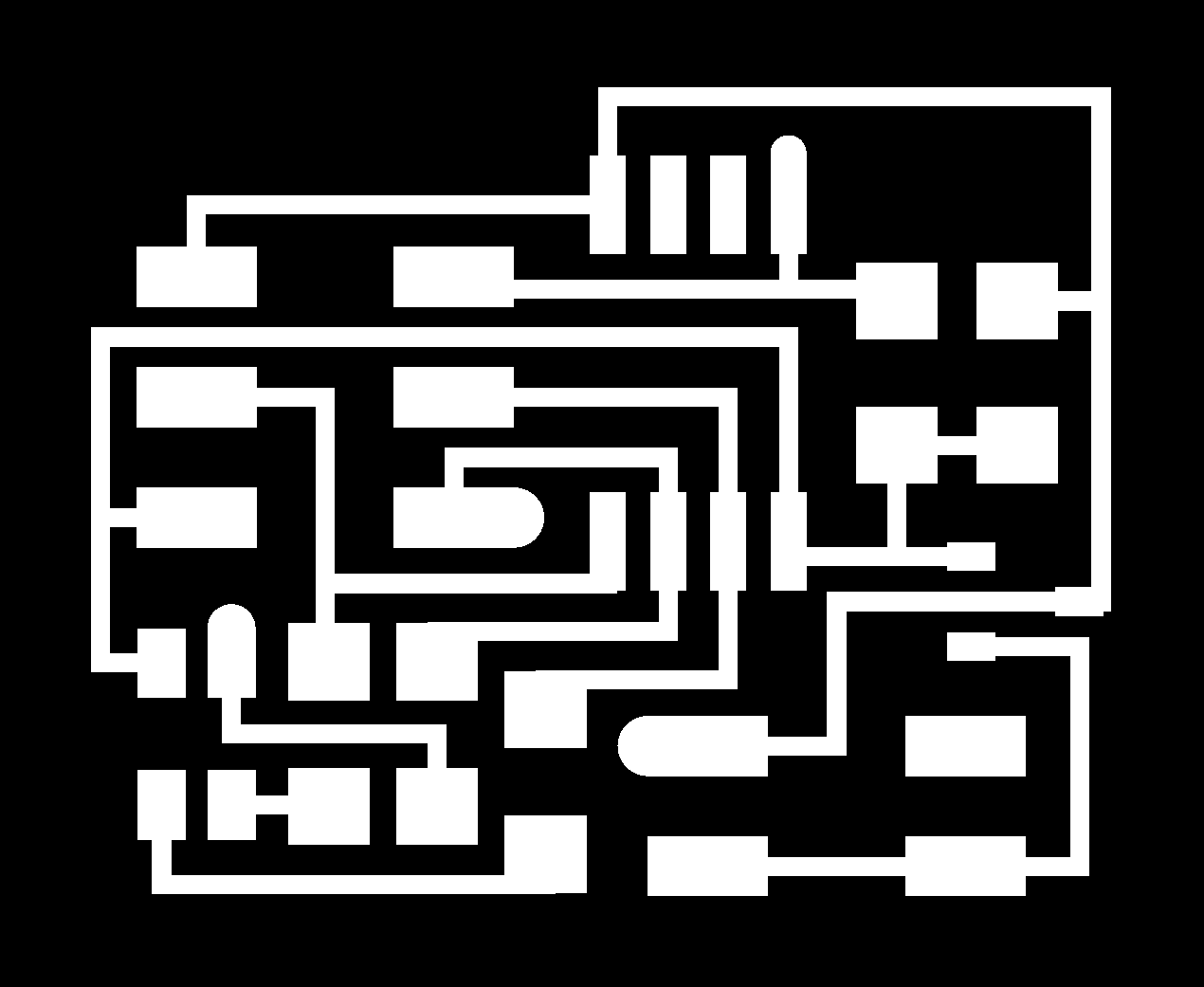
- Tweak and then mill the board
- Populate the board: board
- Tweak the code and load it onto the board
Here is the completed board and a video of its operation below.
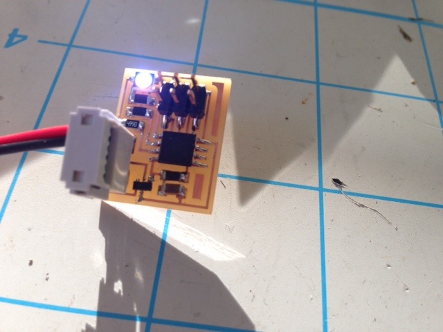
The board built quickly and ended up not having one good solder which I found when toning and then reflowed. The new computer I am using to program with my FABisp worked well and the LED started it's chaging pattern of colors.