Assignments: make the FabISP in-circuit programmer
Surfacing
Normaly we put sacriface layer to avoid scratching of breaking base plate of Modela. Since our sacriface layer of Modela almost came unstuck, I made new one before start milling PCB for FabISP.
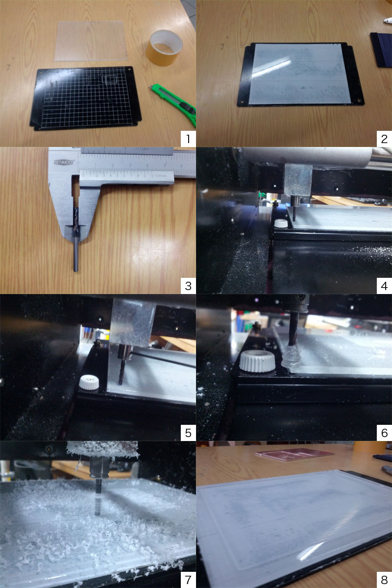
Cut acrylic plate into 20cm x 15cm piece by laser cutter. It is the size of grid on base plate of Modela.
Place the acrylic palte on base plate with double-side tape along with grid.
I used 1/8inch(3.15mm) end mill for surfacing.
type "fab" at terminal > choose "image" as "from format", "Roland Modela" as "to process" >
click "make png rml" > click "load .png" and choose this file >
change setting from "default" to "mill traces(1/64)" >
change parameters (diameter: 3.15, offset: -1, z: -0.3) > set mill to collet short >
press power button of Modela > press view button of Modela >
input 0 to "xmin" and "ymin" > click "move to xmin,ymin" >
press down button till milling bit go down to 4mm above the surface >
Loosen screw of collet and place mill bit on the surface, then tighten the screw so you set origin point of Z axis.
Change "speed(mm/s)" to 15 > click "make .rml" > click "send it!" >
click "Begin Milling" and machine starts millingIf speed had been left as default(4 mm/s), mill bit would be covered with melting acrylic and surfacing would be failed since mill bit heat the trace too much. That's why I had to repeat this 3 times last week.
After cahnging speed, milling dust became like snow flake and top of mill bit wasn't covered with melting acrylic through whole process.
It's done. Surface became flat enough for machining.
milling PCB for FabISP
FabISP is one of fablab-able programmers to give orders to other boards.
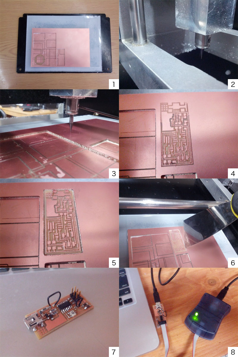
Place PCB on scriface layer
For milling trace, 1/64 inch end mill is used. Setting up machine is almost same as when I did surfacing. But I used This PNG imageinstead and not changed parameters after choosing "mill trace(1/64)".
Since this mill bit is very thin, it should be supported by fingers when it's going down to surface of PCB to prevent it break.
After first milling, there were still some part copper layer remains. So I milled same trace deeper once more.
change "z" to -0.2 from -0.1 > click "make .path" > click "make .rml" > click "send it!" > start millingSecond trial remove all copper layer from trace so I did cutting board with 1/32 end mill.
change mill bit to 1/32 inch > load this image > choose "cut out board(1/32)" >
setting up machine > start millingI removed board with a paddle from PCB.
Solder components to the board as directed by this schematic
Connect the board with PC and AVR ISP mk2 by USB. If it's connected correctly LED turns into green.
Programming
I tried to program the board with Mac.
Download CrossPack and install it. Get code from here.
Then open terminal > go to directory firmware is extracted > and type...
$make clean
$make hex
$make fuse
$make program
After programming, desolder both of jump wire.
If programming succeed, FabISP sould pop-up as usb device when you type command below at terminal.
$system_profiler SPUSBDataType