Assignments:
redraw the echo hello-world board,
add (at least) a button and LED (with current-limiting resistor)
check the design rules, and make it
Designning Main board + Shield
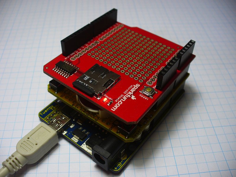
Since the PCB made in this week is supposed to be used for prototyping by rewriting program many times, I came up with the idea that Making two PCB, one is main board and another is shieled board like Arduino so I can easyly change components connected with VCC, GND, and 4 IO port of tiny44 by changing shield board to change not only software but alos hardware.
Using fci socket as pin header
I couldn't find header socket so I tried to use 2x3 FCI pins instead. To do this a little handicraft is needed. Here is instruction.
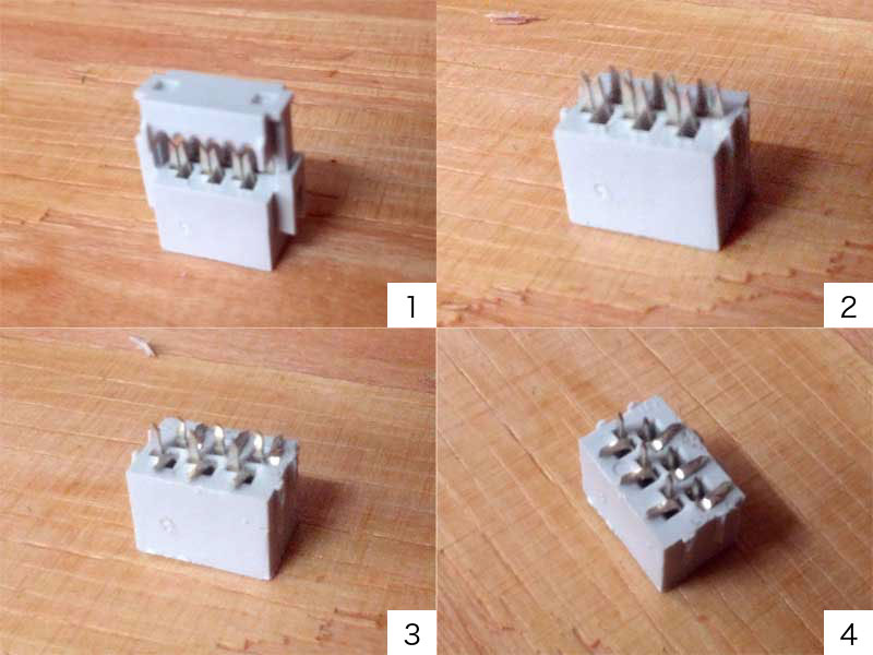
- Mostly we use it as connctor for ISP pin. It has 2x3 conductor and easy to connect with wire.
- Break part of the connector for pinching wire. After removing, you can see conductors like photo.
- Each port has two small conductive legs. Bend one of them like photo.
- Now it's ready to insert to PCB.
Eagle
I did circuit designning with Eagle.
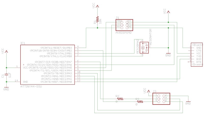
As I mentioned above, Instead of LED and switch, I add one more ISP pin header to the main board as connector to shield board.
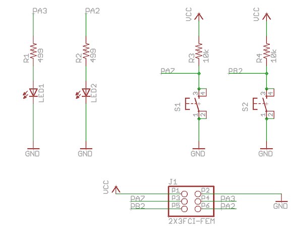
And I put 2 LED and 2 tact switch on the shield board. The main board and the shield board share VCC, GND, and 4 IO ports (PA2,PA3,PA7,PB2) of tiny44 on main board through 2x3 conductor of extra ISP pin header I added.
I made my own Eagle .lib file to use fci socket which fits with ISP pin header.
Editting Layout based on scheme was comfortable since Eagle has useful commands to do that like "RATSNEST" "RIPUP" and "DRC"
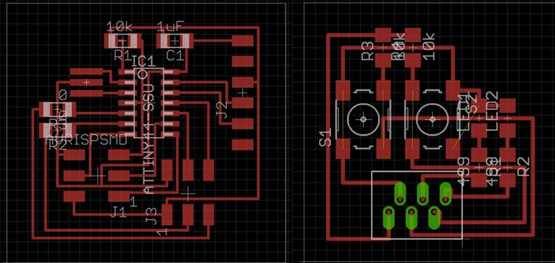
LEFT: Main board, RIGHT: Shield board
milling & soldering
Then I milled board with Modela. I don't mention about how to use Modela in this page but you can check at HERE.
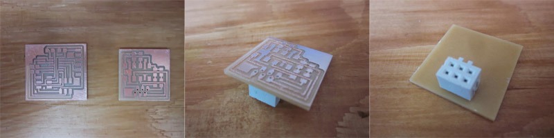
After milling, I did fitting test and fci connector nicely fit into the place it should be.
All other components fit into the PCB as well so soldering was finished without any problem.
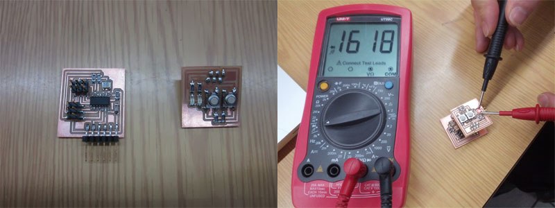 After soldering, I checked LED with multimeter. If LED isn't broken and sticks of multimeter touch right position, it turn on.
Result
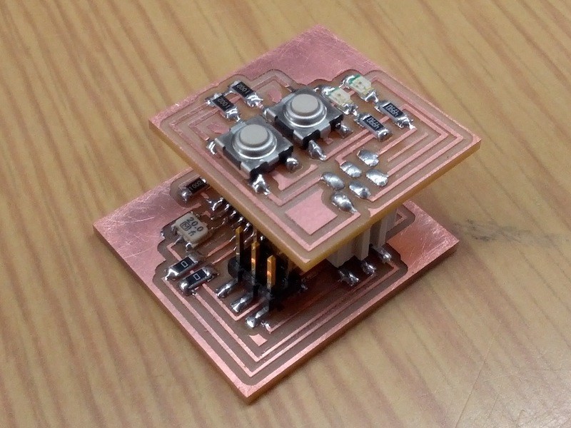
My first helloBoard is done. I'm looking foward to see how it works two weeks later.
Probably I will make another shield (with accelerometer ?)in assignment of "embedded programming".