week 6
- electronics design
- Assignment: draw an Echo hello-world board adding button and LED
The electronic science is, more or less, about playing with electricity in the meaning of working for modulate the electrons flow.
The subject starts with a little confusing convention: electrons flow in one direction but electricity is to be readen in the other way.
I decided to add to the tutorials we were provided, a basic but thick "Encyclopedia of electronic components" in order to try to go ahead with a more solid knowledge.
The assignament is to design, mill and solder a simple circuit trying to add a couple of components as a led and a switch button.

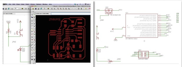
First I got the Echo Hello-world file from FAb page, then I worked it with Eagle software, I selected the components from a library and put them in connection schematically.
Adding a component means put it in the circuit with a logic, following the current flow, in order to work with the other components at certains voltage. Before this, it is to read the datasheet of each component.
This voltage smoothing duty is guaranteed by resistors.
Switches and leds, in the exercise, need different resistor values, to be found in specific datasheets on manufacturers web sites.
Web, then, is full of sites where to calculate Ohm's values for any type of connection.
Connections made, it is to joint the components trough traces following the rules designed in the previous scheme.
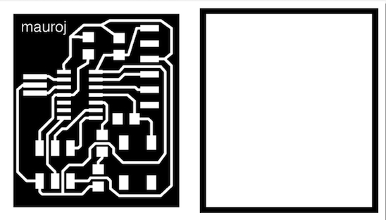
Once all this has been done, it is to export in PNG format on a graphic editor for a black and white look for milling machine.
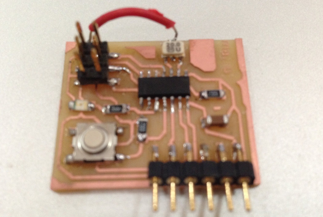
Milling and soldering were pretty much as complex as it was for the ISP exercize due to the size of the SM components.
echo_file


