week 10
- input devices
- Assignment: measure something, add a sensor to the board you have done
Deepening in electronics, discussion gets on inputs devices, which means all the sensors that send to the processor informations through an electrical value. Both analogical and digital pins can receive these values, but with the first ones the signal is much more modulated then digital ones: analog pins can vary fro 0 to 1023, the digital only 0/I or High/Low or 0/5v.
PWM digital pins act like analog ones and can vary the signal from 0 to 255 through percentage of signal on in a specified time: If the signal is on for the 50% of time, the value is 1/2.
There are a lot of sensors, from thermic to movement, these derived transistors can measure almost everything.
I modified the echo Hello-Arduino, adding terminals for all the pins of the 328p Attmega processor.
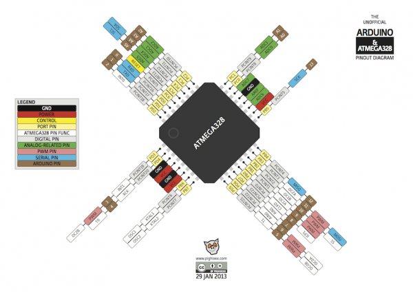
To do that, first thing is to read the datasheet and check this PinOut diagram.
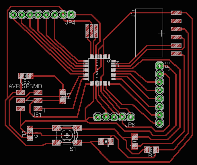
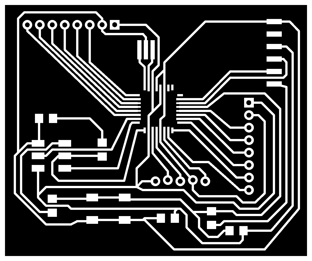
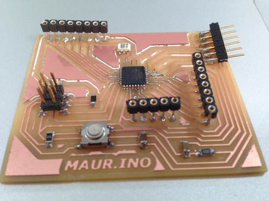
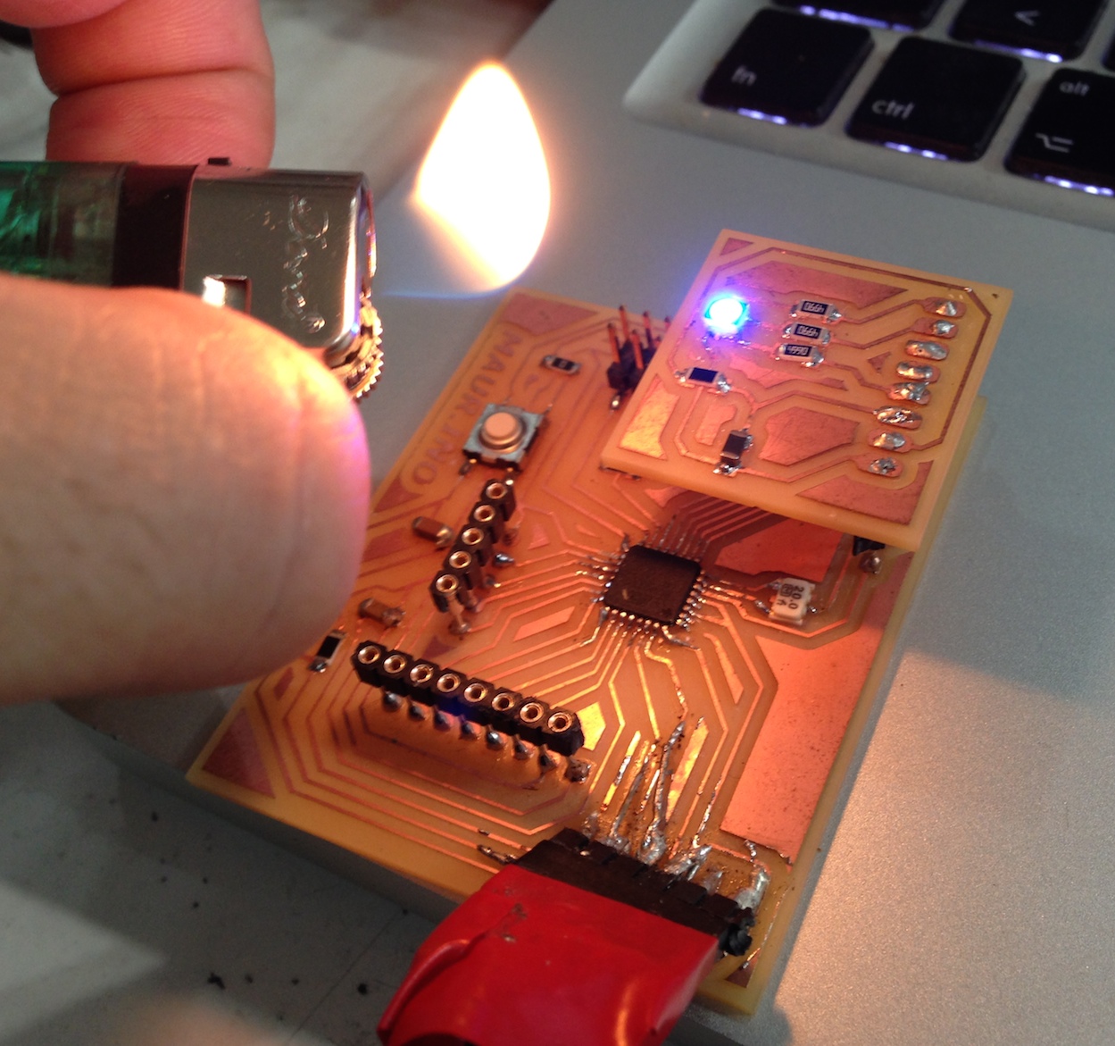
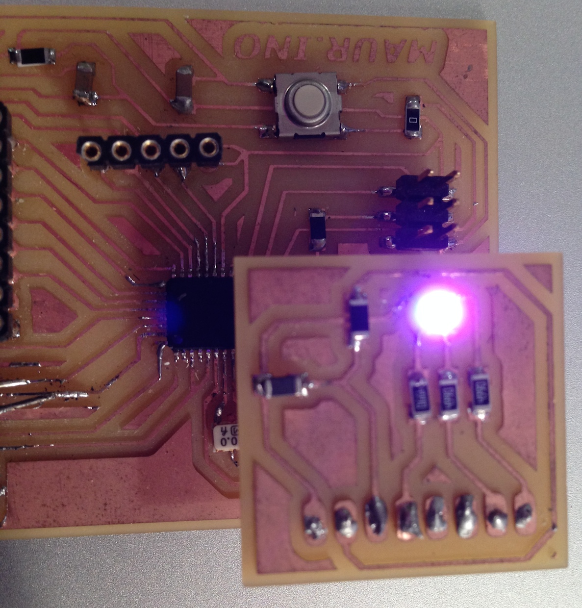
For the assignment it is to build a shield for my copy of Hello-Arduino, as sensor equipment.
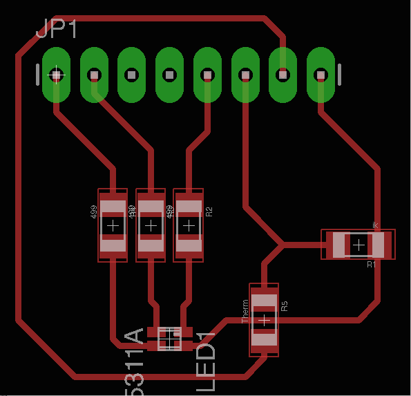
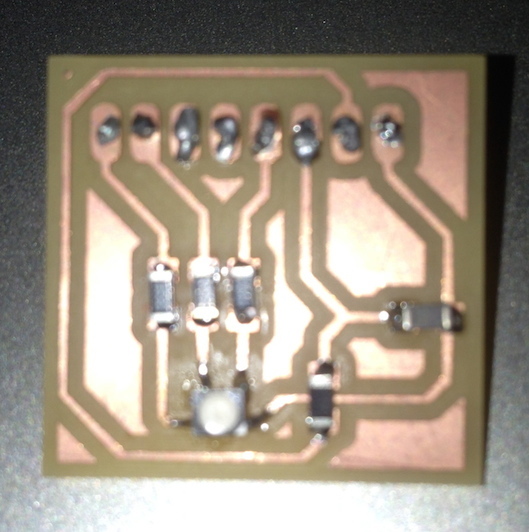
I decided for a thermistor which is a kind of resistor that change different electrical valus depending of external temperature. My shield will be also provided with a RGB led to give an optic response as a thermic colored scale.
I also desarolled the Hello.Arduino board I found in Fab Tutorial, with more headers in order to make it a more versatile board. In datail, I unified all analogic pins in a analogic port. I decided to connect the shield to another port that joins the PWM pins and is able not only to "READ", but also "WRITE", that means that the processor trough the pins is sending a signal to the led.
So I put the led on the Voltage and 3 499 homs resistors on the pins that work as GND.
At the Voltage I also put the Thermistor with a 1k resistor on the GND as digital divide to help sending signal to pin.
This is a tipical scheme for thermistors.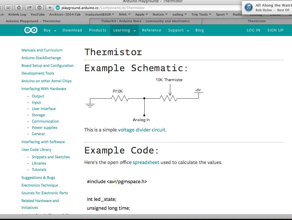 For the RGB led instead, the resistors are between the led and the pins (connections).
The shield’s terminal will be builded downward in order to match the female terminals of the main board.
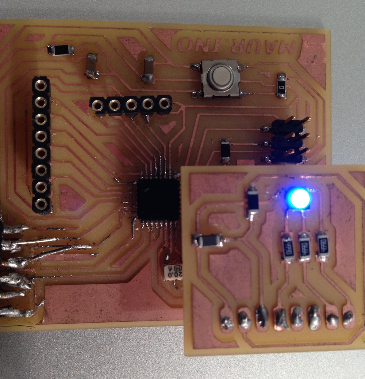
For the code, with thermistors, in case you want to monitor the values you need to convert the electric signal from thermistor in C degrees.
At the moment I’m using a more easier code for just working with the LED.
hello_Arduino
shield
therm_sensor_code
