week 12
- output devices
- Assignment: add an output device to a micrcontroller board you've designed and program it to do something
Output means programming a device to do something wether it is a simple blink of a led or a movement of an actuator.
As said for Input devices, PWM ports can modulate an Output signal giving a wider range of options.
Topic is the theme of voltage. A pin can release at max 0,04 A, which means that if you want to operate a high consumption device, a supplementary battery is required.
A new component appares on the board: the Mosfet. It is a transistor which can regolate the electric tension "V" and permit the processor that work with 5 volts to operate a device at higher V (max24).
It is also very important when the mosfet works with input pins, as the processor would be bourned by an excess of power.
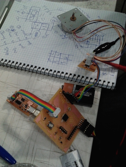
My project is to connect a stepper motor and move it.
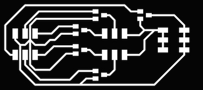
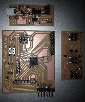
I designed a board with a connection to an external battery. While GND is the same throughout all the circuit, we have now 2 Voltages to handle, 5 and 9 Volts. To do this, I've put a Reductor of power connected with the 5v processor pin on a side and directly with the pin of the motor on the other with 9v.
 Processor pins are 4 and are connected with the motor pin's header through 4 mosfets.
From the motor we have 6 cables: 4 for the pins and two for the voltage (9v.). In this case the pins work as gnd.
To make it work it is necessary that the order of the 4 cables from the motor to the mosfets and pins be clear. Otherwise the motor will just vibrate. The 4 coils inside the motor have an order that must be followed through all the circuit until the processor and on the code in the program.
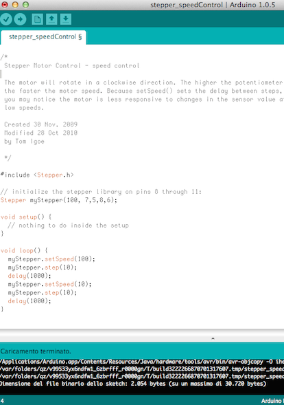
 After all that, al lot of trys, I menaged to load the code correctly havving the motor moving by changing degrees and speed in the code.

