Machine Design
Beeswax 3D Printing Extruder
I joined the group project quite late in the day as the Beehives project had been taking a lot of my time and together with Ferran we had been spending our time trying to make an extruder for printing with beeswax. Unfortunately after trying a few different methods we concluded that it was best to leave the idea for now (it's a really difficult material to work with, it never really solidifies and once it begins to melt it has the consistency of water) and try to assist with the main group project.
MTM Snap
When I came to help with the MTM there was a skeleton crew remaining at the lab. Morale was low but I really wanted to help however I could so I offered my services as a general dogsbody to do whatever was required. The initial request was to assist Francisco with milling some tests of his kokopelli plans. Together with Paul Giron I exported the files to Shopbot format and set up the milling process. Once we examined the results with Francisco it was concluded that the snap-joints were not being milled accurately enough to be used in the machine.

At this point I suggested that maybe we could shift focus to the electronics for a while. This led to me becoming extremely familiar with the G-code interpreter, GRBL.
It began to dawn on me that time was against us and perhaps we couldn't rely on milling the CNC in time so I suggested that maybe we could try a project I had wanted to do for a long time. The Drawbot.
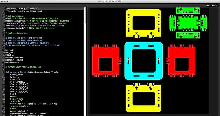
Above: Francisco's parametric version of the MTM snap design
Drawbot
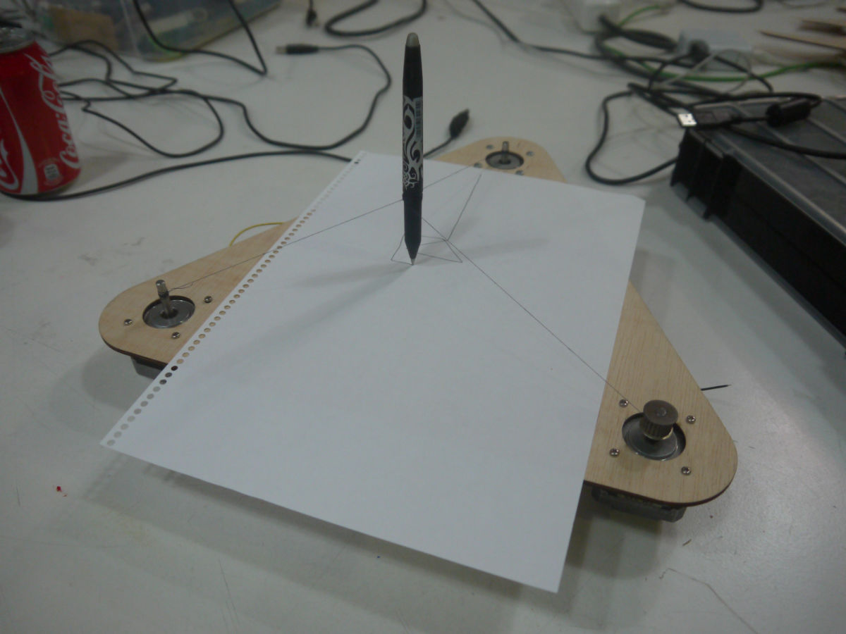
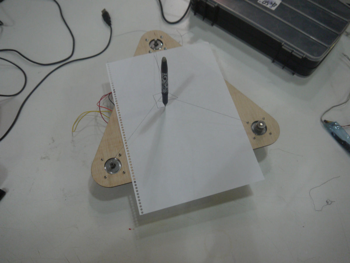
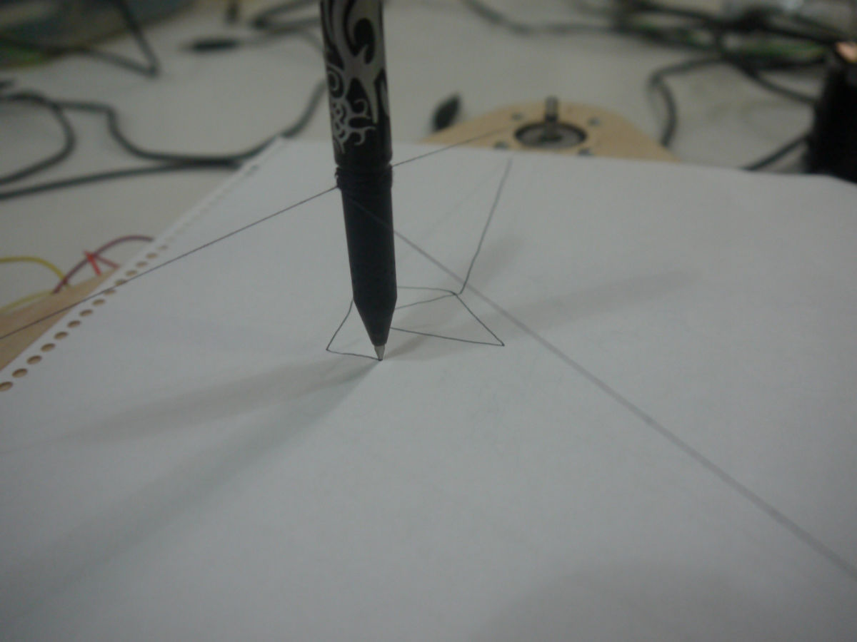
Although I suggested this project I was quite ignorant about existing work. I'd seen versions where there were two steppers on a wall a timing belt dangling inbetween the two - a bit like this, o\__._/o. I just had an idea in my mind about how it might be able to work and wanted to rapidly test and iterate it.
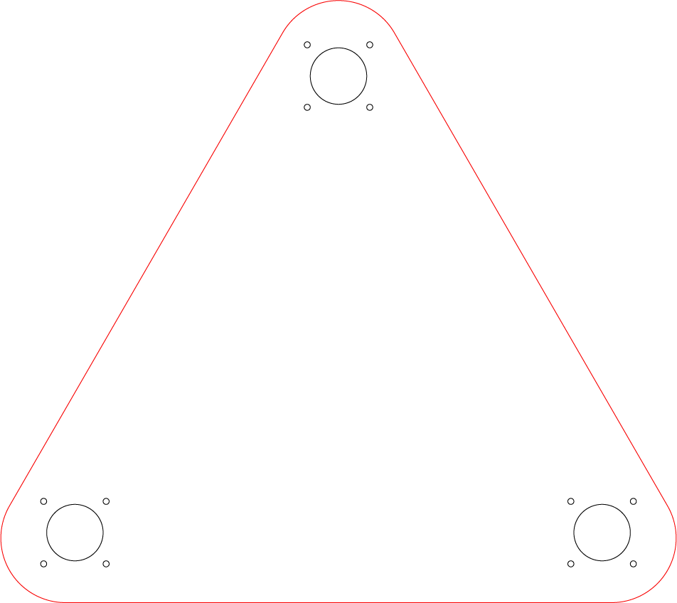
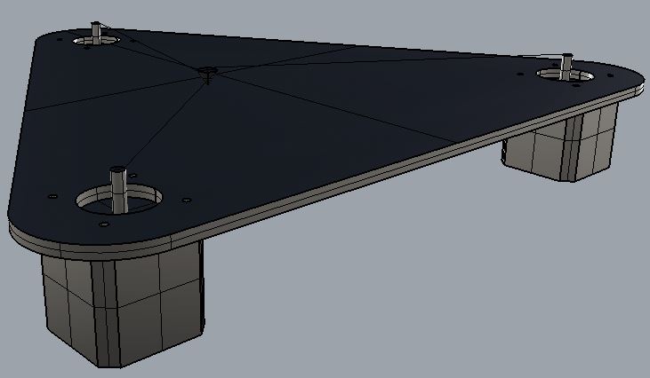
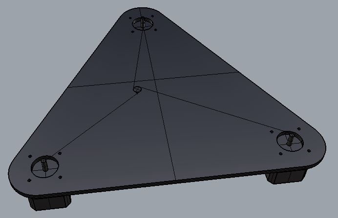
I designed the base parametrically with Grasshopper and Rhino (vector output above). The first one that I made was smaller than the final model was expected to be (I wanted it to accommodate an A4 sheet of paper). Then lasercut it and attached one stepper motor in the corner of each triangle. José Pablo has done some renders of the design below.
After this I developed a simulator in AS3/Flash that you can be interacted with below, click and drag on the paper to draw. (Apologies phones and devices without flash, I was planning on converting it to HTML Canvas when the project was finished).
I got the flash file to send rotation numbers over Serial using arduino-flash-communication-as3-messenger. At this point they were just arbitrary numbers, the plan was to continue to iterate the code alongside the physical model.
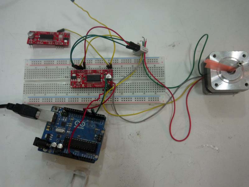
Now I'd made a structure and begun to work on the software implementation, from this point onwards I was at the mercy of the stepper motors. I'd successfully used one with an EasyDriver board back to rotate a platform back in the 3D scanning assignment so I assumed it would be a walk in the park to get them working again.
Boy was I wrong...
During testing I programmed an Arduino UNO to become a GCode interpreter by compiling and uploading the code from https://github.com/grbl/grbl. Once I had done this I was able to communicate with it directly using the Universal G-Code Sender https://github.com/winder/Universal-G-Code-Sender.
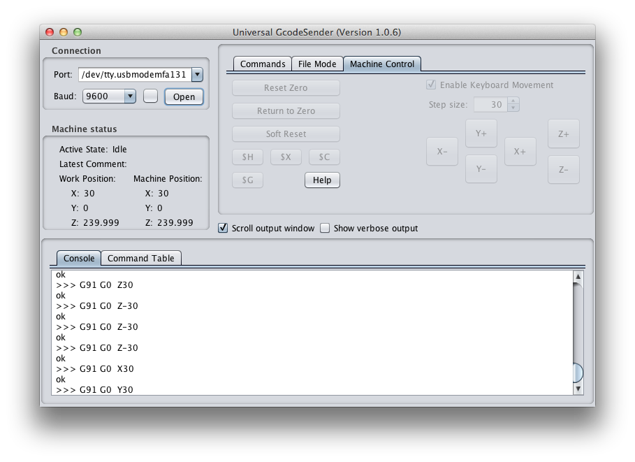
You can verify that your Arduino-compatible board has GRBL correctly installed by pressing the reset button when it is connected via Serial. It should display a message stating the version of GRBL that is installed on it.
Some Tips(?)
After days and days of going in circles, here are a couple of points that might save you some money/time.
- GRBL doesn't seem to like Arduino Leonardo boards. Wasted about 3 days before finding this out.
- Never power an EasyStepper board when there is no stepper motor attached. It will burn out.
- If you use Universal GCode Sender, don't assume that the default settings will work out of the box. Before I was getting any response at all I had to change the values for the number of steps e.g. Z's is $2. You do this by entering $2=400 (or whatever you steppers' settings are) in the command input. You can view all of the current settings by entering $$.
- Make sure you don't misinterpret any pin diagrams (see below).
Output Pin Inconsistencies
I'm probably to blame for this one, but I spent a lot of time thinking that this was the global pin scheme for GRBL board.
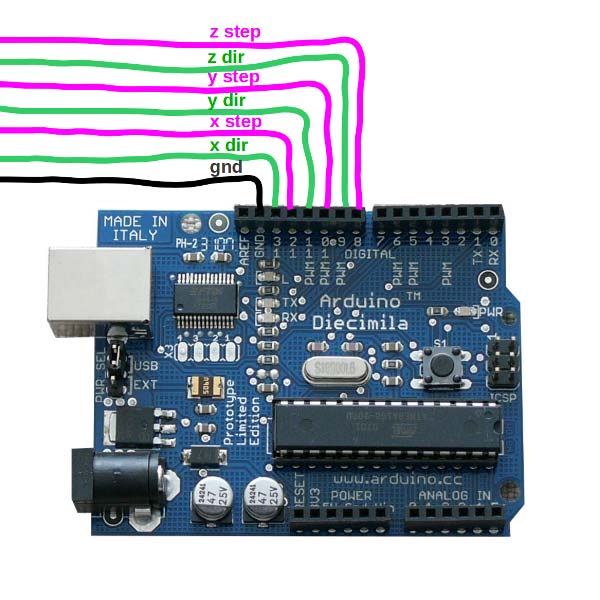
(source: http://mtm.cba.mit.edu/machines/mtm_snap-lock/build/electronics.html)
In the GRBL GitHub docs it has this picture -
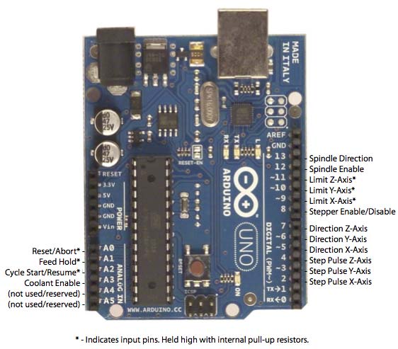
So just make sure that you're using the right pin settings depending on what you are using your board with.
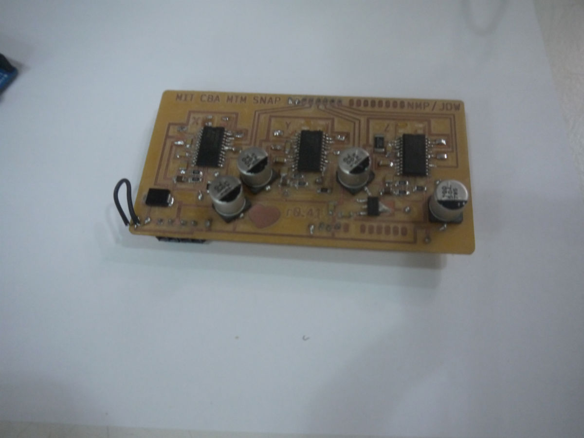
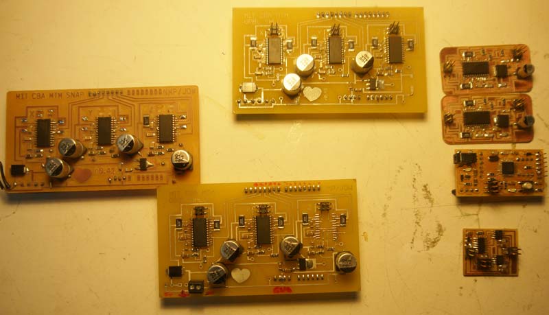
Here are all of the MTM Stepper boards that we made/tested, barring the three faulty(?) EasyDriver boards that we had to hand.
So in the end it saddens me to say that this drawbot project never got to shine like I hoped it would. I have learnt a lot from what we've done and can honestly say that I've spent about three solid weeks on various parts of this assignment - making various beeswax 'plungers', doing odd jobs with the MTM snap and then trying to create the drawbot.
I'd like to take a moment to thank Paul Giron, Francisco Sanchez, JeanPierre Paulet and José Pablo Figueroa Zelaya for all of the work they put in on it.
-
 This is what we were hoping to be able to present
 -
-
 Looks nice doesn't it?

- Computer-Aided Design
- Computer-Controlled Cutting
- Electronics Production
- Computer-Controlled Machining
- Electronics Design
- Molding and Casting
- Composites
- Embedded Programming
- 3D Scanning
- 3D Printing
- Input Devices
- Interface and Application Programming
- Output Devices
- Networking and Communications
- Machine Design
- Applications and Implications
- Project Development
- Final Project - Beehives