3D Scanning
After being presented with several different approaches for DIY 3D-scanning, my head was full of crazy ideas. Thankfully my peers were here to reign them back in a bit. I was determined to get my hands dirty with some electronics again this week so I partnered up with José to build a simple laser scanner.
Laser Scanning
Hacking the Nikon NL-M3 Remote
I own a Nikon D60 SLR camera, which can be remotely triggered by a proprietry remote (RRP $20). Although I own this remote, I am convinced that it could be built for a fraction of that cost.
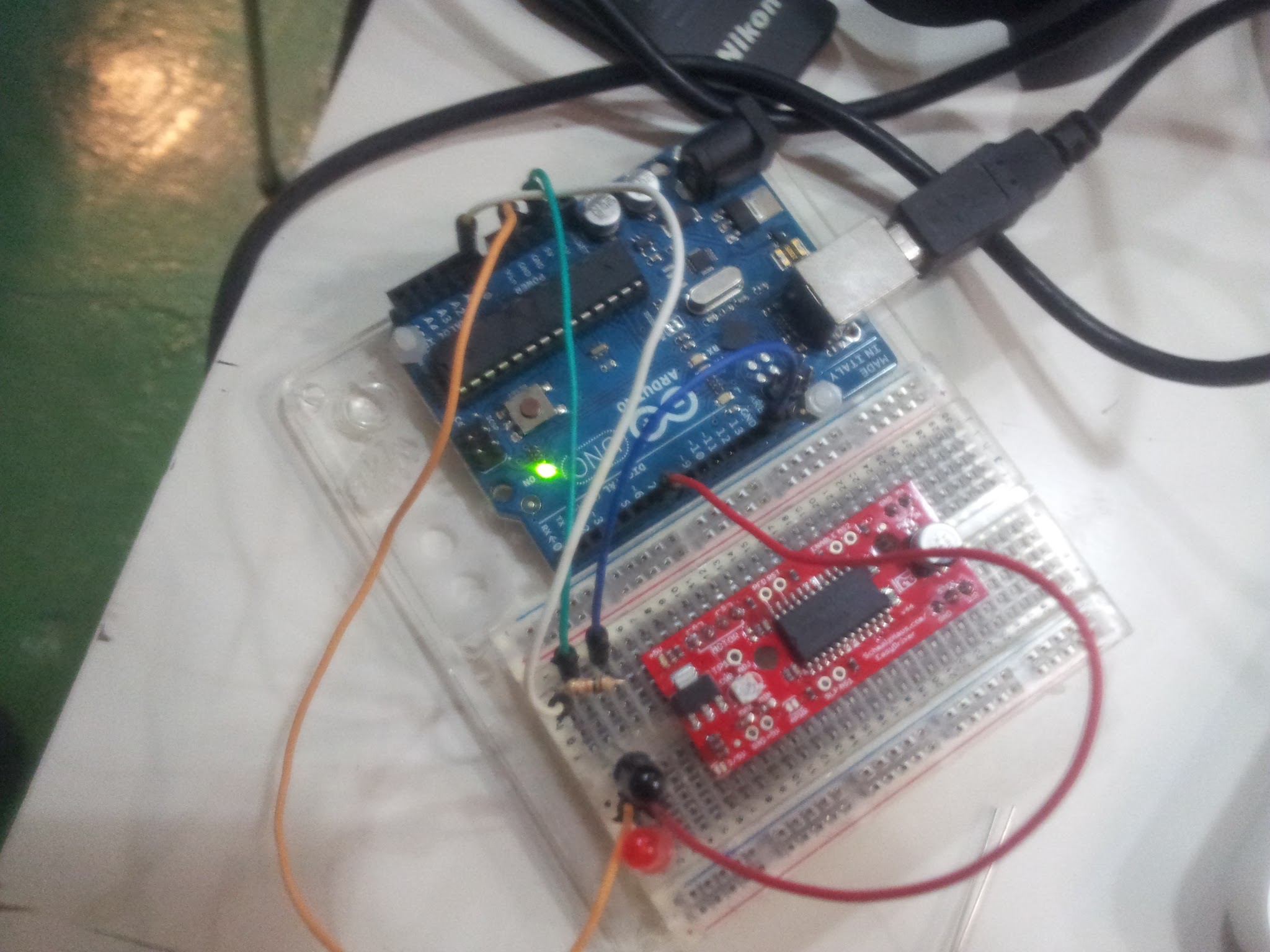
So to begin, I wanted to know if it was feasible for the Arduino to first recognise the infrared signal from the remote, and secondly to try and reproduce its signal, so that we could trigger the camera using an IR LED.
We didn't plan to spend a lot of time on this exercise, it was merely to determine the feasibility of the concept, however I am pleased to say that we managed to acheive both goals relatively quickly.
/*
    Receiver Code
  */
  int val;
  void setup() {
    // set the serial port to 9600
    Serial.begin(9600);
    pinMode(7, OUTPUT);
  }

  void loop() {
    // read analog input pin 0
    val = analogRead(0);

    // here we used 12 because ambient IR noise was about 10
    if (val > 12) {
      // prints the value read
      Serial.print(val + " ");
      // set the red LED on
      digitalWrite(7, HIGH);
      // wait for a second
      delay(100);
      // set the LED off
      digitalWrite(7, LOW);
      // wait 200ms before listening again
      delay(200);
    }

  }
And we found this code snippet which we adapted for our needs to send the correct IR light pulses to trigger the camera.
/*

  LUCKYLARRY.CO.UK - IR Remote control for Nikon using Arduino

  Mimics the infrared signal to trigger the remote for any Nikon camera
  which can use the ML-L1 and ML-L3 remotes. Can be used as an intervalometer
  for time lapse photography.

  The IR sequence I used is originally taken from: http://www.bigmike.it/ircontrol/

  You should be able to use my pulse methods to alter to suit other cameras/ hardware.

  micros() is an Arduino function that calls the time in Microseconds since your program
  first ran. Arduino doesn't reliably work with microseconds so we work our timings by
  taking the current reading and then adding our delay on to the end of it rather than rely
  on the in built timer.

  */

  int pinIRLED = 13;                                      // assign the Infrared emitter/ diode to pin 13

  void setup() {
    pinMode(pinIRLED, OUTPUT);                            // set the pin as an output
  }

  // sets the pulse of the IR signal.
  void pulseON(int pulseTime) {
    unsigned long endPulse = micros() + pulseTime;        // create the microseconds to pulse for
    while( micros() < endPulse) {
      digitalWrite(pinIRLED, HIGH);                       // turn IR on
      delayMicroseconds(13);                              // half the clock cycle for 38Khz (26.32×10⁻⁶s) - e.g. the 'on' part of our wave
      digitalWrite(pinIRLED, LOW);                        // turn IR off
      delayMicroseconds(13);                              // delay for the other half of the cycle to generate wave/ oscillation
    }

  }

  void pulseOFF(unsigned long startDelay) {
    unsigned long endDelay = micros() + startDelay;       // create the microseconds to delay for
    while(micros() < endDelay);
  }

  void takePicture() {
    for (int i=0; i < 2; i++) {
      pulseON(2000);                                      // pulse for 2000 uS (Microseconds)
      pulseOFF(27850);                                    // turn pulse off for 27850 us
      pulseON(390);                                       // and so on
      pulseOFF(1580);
      pulseON(410);
      pulseOFF(3580);
      pulseON(400);
      pulseOFF(63200);
    }  // loop the signal twice.
    delay(1000);
  }

  void loop() {
    takePicture();                                        // take the picture
    //delay(1000);                                          // delay in milliseconds which allows us to do timelapse photography - 1 second = 1000 milliseconds
  }
Making a Rotating Platform

Now we had a working method for triggering the camera, the item we scan would need a platform. We found a stepper motor in the inventory and after a few hours of fiddling about with it we managed to power it independently and control its movement with the Arduino. We did not power it with the Arduino for extended periods of time as it was drawing lots of power from the board and we were anxious not to burn out the board.
Next I took a quick measurement of the shaft diameter and designed a dozen holes at 0.1mm intervals parametrically in Grasshopper. These were laser cut them from acryllic on the LaserPro Spirit, speed 8 and frequency 99. It was important that the platform would be was a very tight fit on the shaft. After doing this I simply cut a 10cm circle with the hole in the centre and pressed it onto the shaft. To celebrate this minor acheivement I made this gif of Mario spinning around on it.
The final code we used to turn the platform, and trigger the camera shutter is below -
int pinIRLED = 11;

void setup() {
  pinMode(8, OUTPUT);
  pinMode(9, OUTPUT);
  digitalWrite(8, LOW);
  digitalWrite(9, LOW);
  pinMode(pinIRLED, OUTPUT);
}

void pulseON(int pulseTime) {
  unsigned long endPulse = micros() + pulseTime;
  while( micros() < endPulse) {
    digitalWrite(pinIRLED, HIGH);
    delayMicroseconds(13);
    digitalWrite(pinIRLED, LOW);
    delayMicroseconds(13);
  }

}

void pulseOFF(unsigned long startDelay) {
  unsigned long endDelay = micros() + startDelay;
  while(micros() < endDelay);
}

void takePicture() {
  for (int i=0; i < 2; i++) {
    pulseON(2000);
    pulseOFF(27850);
    pulseON(390);
    pulseOFF(1580);
    pulseON(410);
    pulseOFF(3580);
    pulseON(400);
    pulseOFF(63200);
  }
  delay(2000);
}

void loop() {
  for (int i = 0; i < 150; i++) {
    digitalWrite(9, HIGH);
    delay(1);
    digitalWrite(9, LOW);
    delay(1);
  }
  takePicture();
}
Introducing the Laser
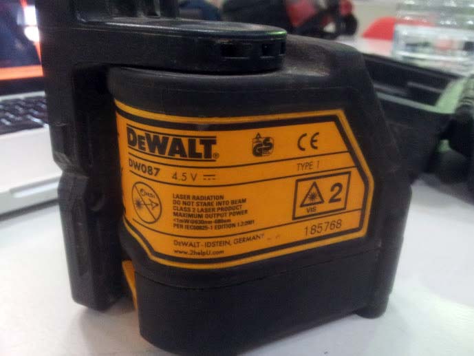
We had a DeWalt DW087 lying around, so after spending 10 minutes working out how to keep the beam constant rather than blinking (it needs to be level) we placed it in the corner of our makeshift box.
Following the advice on this Instructables post , we decided to positioned it at roughly 15° to the angle of the camera and the shaft of the motor (centre of the subject). We didn't have a protractor, so we just printed one!
The Final Setup
We tried to scan several objects. Ranging from an apple to a plastic leopard, but it saddens me to say that our results weren't particularly accurate, or usable.
Lessons Learnt
Your scanning resolution is limited by the width and the clarity of your laser line. I think our beam was probably too thick for the size of objects that we were trying to scan, but it might be perfect for a human face or something larger.
Along with the width of the laser, we needed to take many more scans. So a smaller rotation before each photo.
123D Catch
123DCatch is a service offered by Autodesk, the makers of AutoCad. The premise is simple, take lots of clear photos of a subject, from as many angles as possible and then upload them to their servers which tehn run matching algorithms to estimate the 3D shape of what you photographed.
I tried to scan several things with this web-based software and had a terrible time. Although Juan got very good results using 40 photos of his head. I think this will be my final method choice for 3D scanning so watch this space!
One thing I learnt with this service was that you should try and make your subject fill the entire frame for each photo, make sure you have a varied background and ensure the entire frame is both well-lit and in focus. That being said, I'm yet to produce any good results with this service so perhaps there is more to it than that!
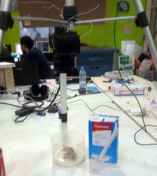
Milk Scanning
I was intrigued by milk scanning although before I even tried it I could see inherent flaws that I assume are overcome with expensive equipment. For one, I am guessing that you can only scan half an object at a time, and even then it will only work well if each succeeding layer of the object is smaller than the last. Like the top half of a ball. Another issue I could forsee would be if there were any parts protruding at less than a 90° angle to the camera, as images collected would not be able to determine the depth as it would be obscured by the 'top face'.
Despite this, I wanted to give it a try. Initially I thought I'd try other liquids such as coke, but then realised why milk was such a good candidate - it's opaque.
The capturing process itself was very straightforward. Secure your object with some putty, add a couple of teaspoons of milk, take a picture, add more milk etc. As I was feeling slightly pressured by time at this stage I hung my camera precariously from a tripod used the Nikon remote mentioned earlier. It would be very simple to replicate this setup using an Arduino and a button using the IR code above though.
I began to try to process the second half of the image sequence I had, and convert them into 'contours' for a 3D shape, but quickly realised that despite my best efforts with Photoshop's batch actions, I'd have to do a lot of timeconsuming manual work to get any workable results.
Stuff I Learnt
One mistake that I made that can easily be avoided is to set the focal distance on your camera with autofocus and then switch it to manual focus. By neglecting to do this, once the container was 2/3 full of milk the camera would not take a picture as it has a common(?) built-in setting to instead set the white-balance when it focuses on a plain white surface.
As I was borrowing the leopard from Ramin I was reluctant to vandalise it, but had it been mine I would have definitely followed Mick Jagger's advice and painted it black.

- Computer-Aided Design
- Computer-Controlled Cutting
- Electronics Production
- Computer-Controlled Machining
- Electronics Design
- Molding and Casting
- Composites
- Embedded Programming
- 3D Scanning
- 3D Printing
- Input Devices
- Interface and Application Programming
- Output Devices
- Networking and Communications
- Machine Design
- Applications and Implications
- Project Development
- Final Project - Beehives