Juan Ranera
Fab Academy 2013 Participant
Electronic Design
The assignment for this week is redraw the echo hello-world board, adding at least a button and a LED. The ATtiny44A is a small and
cheap microcontroller that are convenient for running simple programs. After looking at the datasheet I decided to connect the switch
to pin PA3 and the led, with a resistor, to pin PA7. I left over two pins, so I decided to add two more connectors.
Each connector have its own power to connect e.g. a distance sensor in the future.
There are several programs to draw the schematic and PCB board. I have worked with Orcad and Altium before, so I decided to install
Eagle to test it. The advantage of using Eagle is that you had all the libraries of the hello world componentes.
After trying it for a bit I decided to draw my circuit with Altim because it has more options and is faster.
Schematic design
Schematic design is the most important step because any error would spoil the later work. The first thing I did was to download and install the atmel library. Once located the ATTINY44 I continued with the other components. The problem was that the footprints of the crystal and the button did not correspond to those used by us, so I had to recreate them using the Component Wizard tool. To finish my project I compiled and checked if it had any error in the design with the verification tool.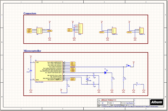
PCB design
Once all components had been exported to PCB layout without warnings, I defined the rules of my design. The most important rules that I modified are:CLEARANCE: 0.4mm between tracks
MIN WIDTH TRACK: 0.4mm
MAX WIDTH TRACK: 0.5mm
ROUTING LAYERS: TOP LAYER
SOLDER MASK EXPANSION: 0.2mm
PLANE CLEARANCE: 0.5mm
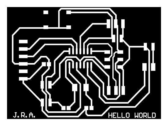
After it, I placed the components in the most logical position to reduce the number of tracks. I didn't use the "autorute" because the board is small and you always have to do modifications. I've used a resistence of 0 ohms to make a bridge and trough a track below.
Finally I exported the drawing as PDF and I opened it in Inkscape. I adjusted the board measures. I added 60 pixels to the cutting board with a contour, and I exported it as a bitmap 500ppp.
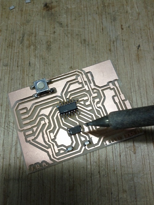
Then I set the printer Modela with the two images .png and I started printing. When all components were soldered I finished all the process and this is the final result.