Juan Ranera
Fab Academy 2013 Participant
Research, Development and Innovation department of Esclatec
This week, I have drawn some platform parts for my final project. Initially I've used the Pro Engineer for drawing because I had worked a bit with this program before and I couldn't lose a lot of time discovering a new one. Iíve also been testing Rhino and Iíve understood the reason why many people had recommended me.
The first thing I've done is a list of all the components and its measures. From this list Iíve thought about how all the pieces could be placed.
Keeping in mind that the maximum diameter couldn't be bigger than a conventional chair, IĎve defined the chassis measures. (If the platform is too large, will be a problem to pass through the gates).
Version with Pro Enginner
I have drawn one of the four arms, the holes where the engine is subjected, the holes to put up the control board and the holes that fix the arm with the central node.
.jpg)
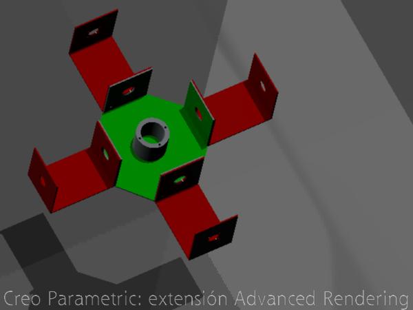
After it I have drawn the central node. This node has four walls to fix the four arms. Inside I will put two batteries and an electronic board.
.jpg)
In the central part I have drawn a leaky cylinder to insert a conventional chair or a platform.
.jpg)
Finally I applied a render of the whole

Version with Rhino
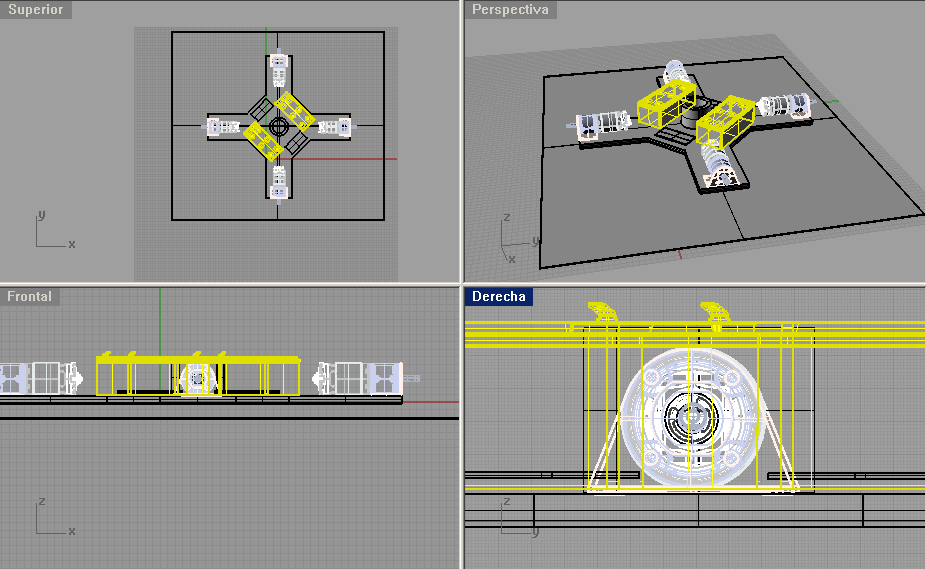
The drawing done with Rhino is a little different. It has a base formed by only one piece. Inside Iíve put two batteries, two control boards and four engines. In the central part I have painted the cylinder for clamping a chair or a platform.

.jpg)
