


WEEK 09 : DESIGN AND MAKE SOMETHING BIG!
Assignment Overview
This weeks assignment was to design and make something of a larger size and to encompass Computer Controlled Machining processes. We have joined forces with Annemie from OKNO, a Belgian Apiculture specialist and artist. Together with John Rees and Ferran Massip (Team Bee) we have been tasked with making several beehives for use at Valldaura Labs and at the Fab Lab Bcn. We have had to think about Tooling, materiality, processes for Large format pieces.
Design Adaption and the Open Structures Grid
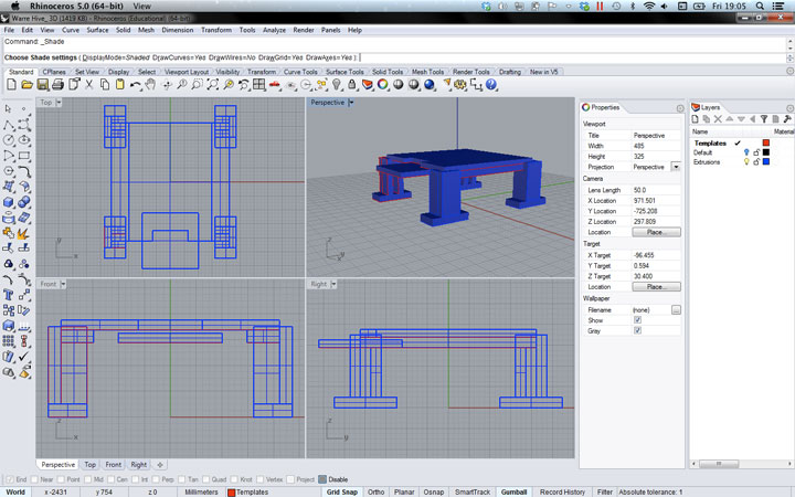
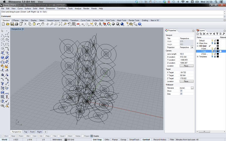
Open Structures is a social network and design repository for sharing and compiling components and objects. It uses a set grid as a design constraint so that users may create components for designs that will correspond and work together. Our initial task was to adapt the Warre Hive by Emile Warre. It is also known as 'The peoples hive'. The hive has subtle aspects to its design that are important not to corrupt or change when adapting it for the OS Grid.
Materials
We had initially been asked to use recycleable materials or pine wood cut from the forest at Valldaura. However we decided finally to use 20mm Okume plywood for several reasons; availability, reduction in preparation time, regitity, cost and aesthetics. Along with this we wanted to limit the necesity for glue fixings, the entire structure would be assembled using screws. The view window would be made of transparent perspects and in front of that a layer of foam for heat insulation.
Tooling and Workflow
The design was relitively simple compared to organising the fabrication process. Arranging each component in a flat layout and organising all the different aspects of the design it became clear that it was necesary to use both the 'Laser Cutter' and the 'Shopbot'. Several attempts at designing only for the milling machine but the engraved pattern would not have been fine enough using only a drill bit, there were too many 90 degree angles that would have needed finishing and the entire cutting process could have been measured in geological time frame.
Convential machining vs Climb machining. Lead in and lead out. Wealding .. Arch welding is increasingly not used. Sonic Welding. Friction Welding.
Tool Paths
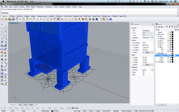
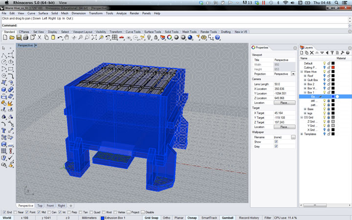
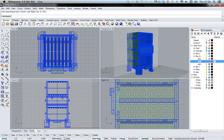
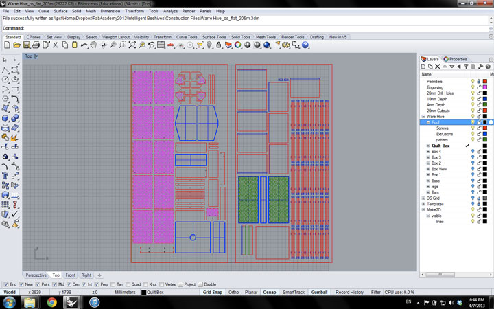
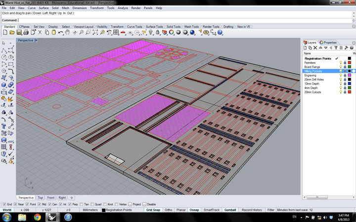
Having separated out all the necesary tool pathways, i then installed and experimented with RhinoCAM, Partworks 3D and Partworks V2.5. I found that RhinoCAM was particularly usefull with a clear and detailed set or options and parameters. The tool paths to the side show the paths and tool path divisions. Included here is also a 3d model that was to be exported as an .stl file and used with Partworks 3D. From the pockets created using the SHOPBOT the Plywood panel would then be taken over to the laser cutter to go through all other cuts and engravings. Registration marks were necesary to make the transfer zero points accurate to the millimeter.
Tips and Tricks
- Cutting air : why not set off the machines paths above the material first to quickly check its not going awry.
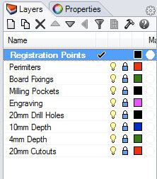
- Registration Points : Mark out registration points first to help you know what the machine is doing and where to drill.
KEY RESOURCES:
Week 9 Class Lecture : Computer Controlled Machining
Week 9 Howework Review
Week 9 Blog : Make Something BIG!