WEEK 05 : 3D SCANNING AND PRINTING
Milk Scanner
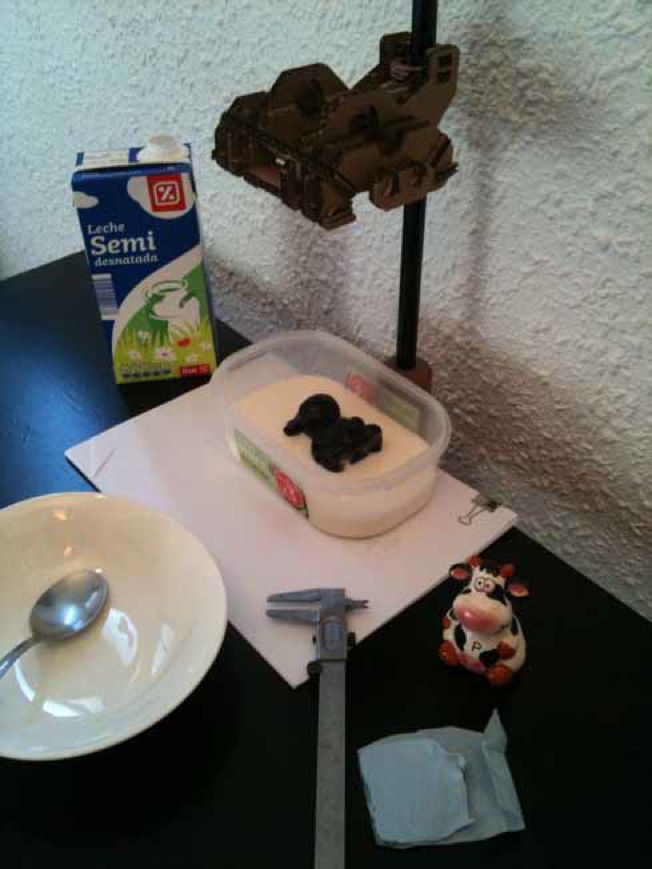
This Weeks task is to scan, to adapt and to print a 3D object. I chose to use the Milkscanner app, to the side is a short video made by the developers of the Milkscanner. The methodology here is to use an opaque fluid to mask part of the object, then by creating snapshots of the object through stages of submersion it is possible to produce a series of layered contours that can then be assembled into a displacement map.
I have found the documentation of the Milkscanner project on the Instructables Website and their own Milkscanner Website and Wiki Forum to be lacking. The info gaps are in the details regarding the initial install, how to use and go through the steps of scanning, producing or tracing images and creating a displacement map. All physical components are listed below:
- webcam
- webcam rig
- liquid container
- milk
- object
App was a red herring.
After a very long istallation and debugging period, I found that the app itself was unintuitive and difficult to control. This led me to take photos of the stages of submersion oof the object manually. I did this by using the iphone bike cradle that i designed during week 3 to hold the phone. I also found that because of the miniscus of the milk it was better to take the photos starting from a fully submerged position and then gradually revealing the object 3 spoonfulls of milk decanted at a time. Another problem was that bubbles formed in the milk and some dust and paint flakes made the images difficult to clean. I did too passes of photos on the object, one from the front and one from the back. I would later have to join these together.
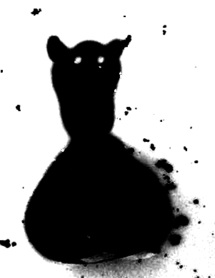
Creating Contours
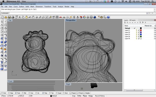
I needed to create a series of contour vectors from the Jpegs that I had taken. This mean one by one cleaning up the images, removing any colour and adding a contrast and brightness filter using photoshop. I used these to create the .GIF on this page. Finnally when I had each photo in a black and white high and clean i used Illustrator to live trace the edge of the black object and to extract a vector curve. I also left a square frame around the image so that I could locate the vectors at a later date. I now had a series of vectored contour shapes that I could import into a 3D program one by one and arrange in a stack to form the shape.
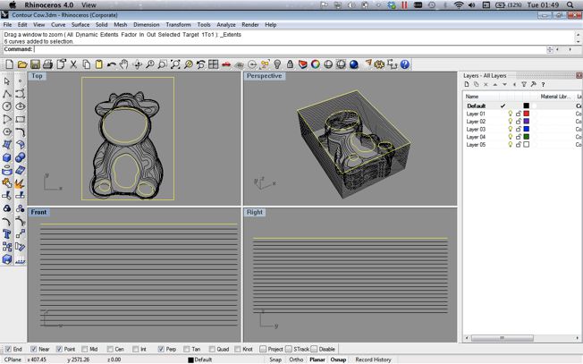
3D Construction and Adaption
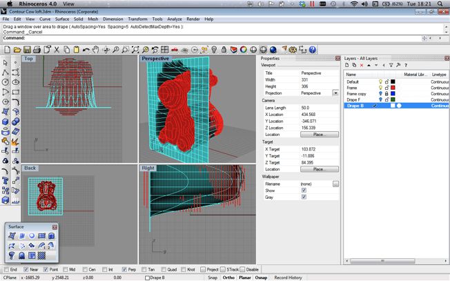
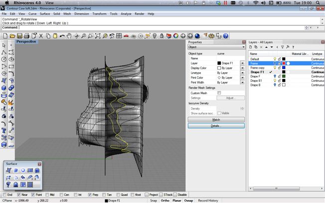
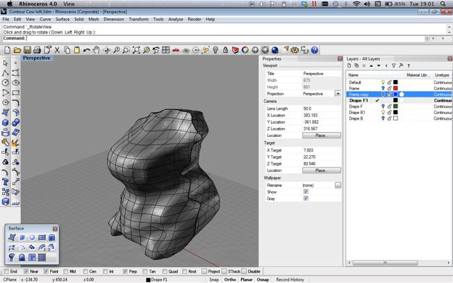
I used Rhino to arrange and stack the contoured vectors. I was surprised at how well the Cow model looked at this time. However I found it very difficult to join the contours together to create the final mesh that I needed. I will list below the methods that i tried using rhino and the problems that i encountred using them.
- Loft : I tried to loft each curve to the next in series, however I found this created kinks and twists. There was also a problem linking in multiple end points into one curve
- Grasshopper : This looked like the most promising method. Placing the same number of points on each curve and then linking them.
- Drape : This tool allows you to drop a mesh over the objects and let that make assume of the form of the objects below.
- Cinema 4D : This program has tools to cloth an object much in the same way the Drape tool can. It can also loft the contours also.
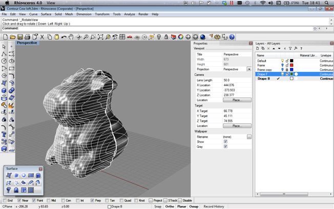
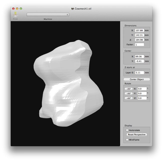
In the time constraints I found that the most successful way to join the mesh was by using the drape tool from two sides (front and Back) and then using then trimming the extra drape mesh at the point they intersect. This created a very dull version of the original contour setup and allowed only for some control. It did however proce a mesh that I was then able to sculpt and adapt in a limited way. From Rhino I was then able to export a .stl file that could be read by the machine and 3D Printed.
Another way to do this is to use Netfab or Meshlab to edit adapt and change your meshes. This helps to produce and export a better quality .stl file.
3D Printing and Creating Print Paths
During the week we had been show two machine types. The Makerbot : Replicator 2 and the 'Spectrum Z510'. These differ greatly in their functionality and ability, and produce different print results too. Makerware software command line script .s3g or .x3g makerbot specific version of 'gcode'. that takes geometry from an .stl and translates it into machine instructions. These file types can then be plugged directly into the destop printer using SD card or a USB connection. The use of a portable storage device means that you can leave it in the machine and take away your lapton whilst the job runs. The machine extrudes of PLA or ABS plastics and builds the object layer by layer. Powder reserviour gives support to the object whilst it is being formed.
Printing using the Replicator 2
Key Terminology: Xcode, Openframeworks, IDE, C Language, C++
KEY RESOURCES:
Week 5 Class Lecture
Week 5 Homework Review
Week 5 Blog Post : Which Atoms and Whose Bits?
My Twitter Account : @jonnyminch