
WEEK 03 : COMPUTER CONTROLLED CUTTING
Designing 2d for 3d assembly
The first of this weeks taks was to build a structure to be designed to be machined by the lasor cutter and for cardboard construction. The structure would use CAD software and to be concieved with the understanding that it should be assemblable using a push-fit method. More than just design representation of the previous week, these CAD drawings would be in a more technical form. Meaning that the vectored shapes were to be turned into a physical object. These drawings are the DNA of a real object. Shapes were to have male and female connectors and fittings ready to push-fit together to be assembled later. A design method such as this could be used to create a set of adaptable, interlocking pieces, much like lego. However I have chosen to make a fixed one off object to achieve this task.
Testing and research purpose
I have designed cradle unit that will be mounted on the handle bars of a racing bike and will carry an Iphone 3gs. This project will serve a research and testing purpose for the wider Entrapillor Dynamo project. It will do this by facilitating the mapping and testing of the accelerometer embedded in the iphone in relation to the turning movement of the bike. The objective of the testing will be to analyse and measure how effective the accelerometer is at judging when a rider turns the bike and whether this can be used for the purpose of indicating.
Connecting objects.
The cradle will sit between and connect two objects; the phone and the handlebars. When designing it was imperitive to understand the points of connection, the pressures and the strengths that would act on the cradle to hold it in place safely and prevent the i-phone from slipping also. The design would also have to encompase a fit and release mechanism so that it could be removed from the handlebars, or the phone removed from the cradle.
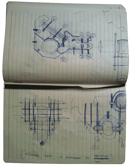
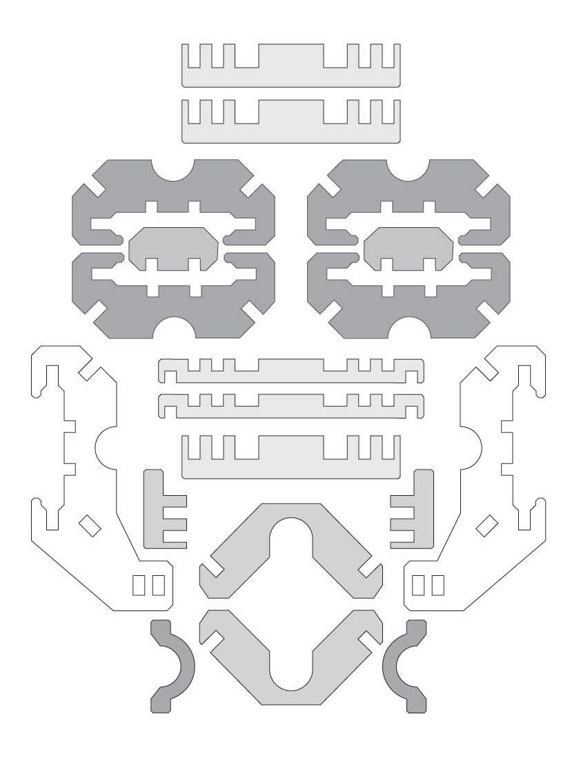
A Push-fit lattice
The card of 6mm thickness would work most efficiently when tightly packed; this meant creating as many structural components from one piece of A3 card as possible. Less wasted space from the card would also prove to be a plus point. I first sketched the idea out using pen and paper then used adobe illustrator to measure out my drawings more accurately. Illustrator allowed me to easily change dimensions and to create quick and effective changes to the design. I would have liked to have used Grasshoper for this section but have had trouble installing it on a mac with limited processing power and an older graphics card. I also tried inkscape and openscad.
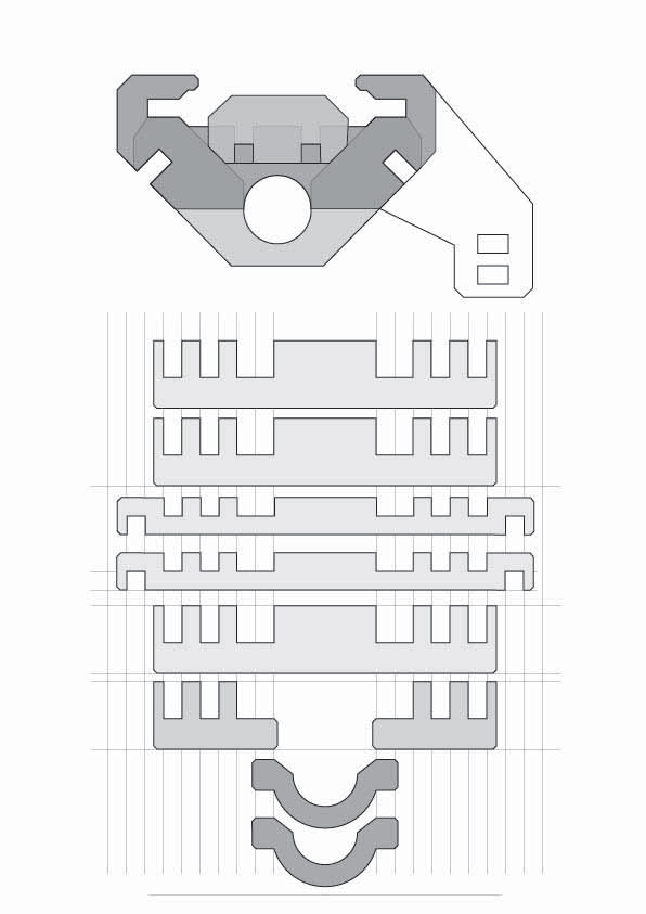
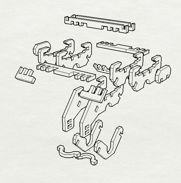
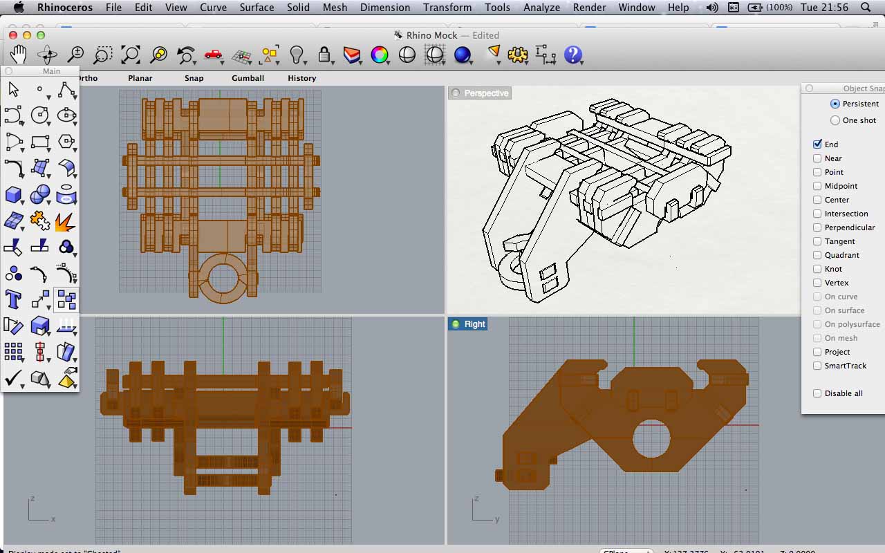
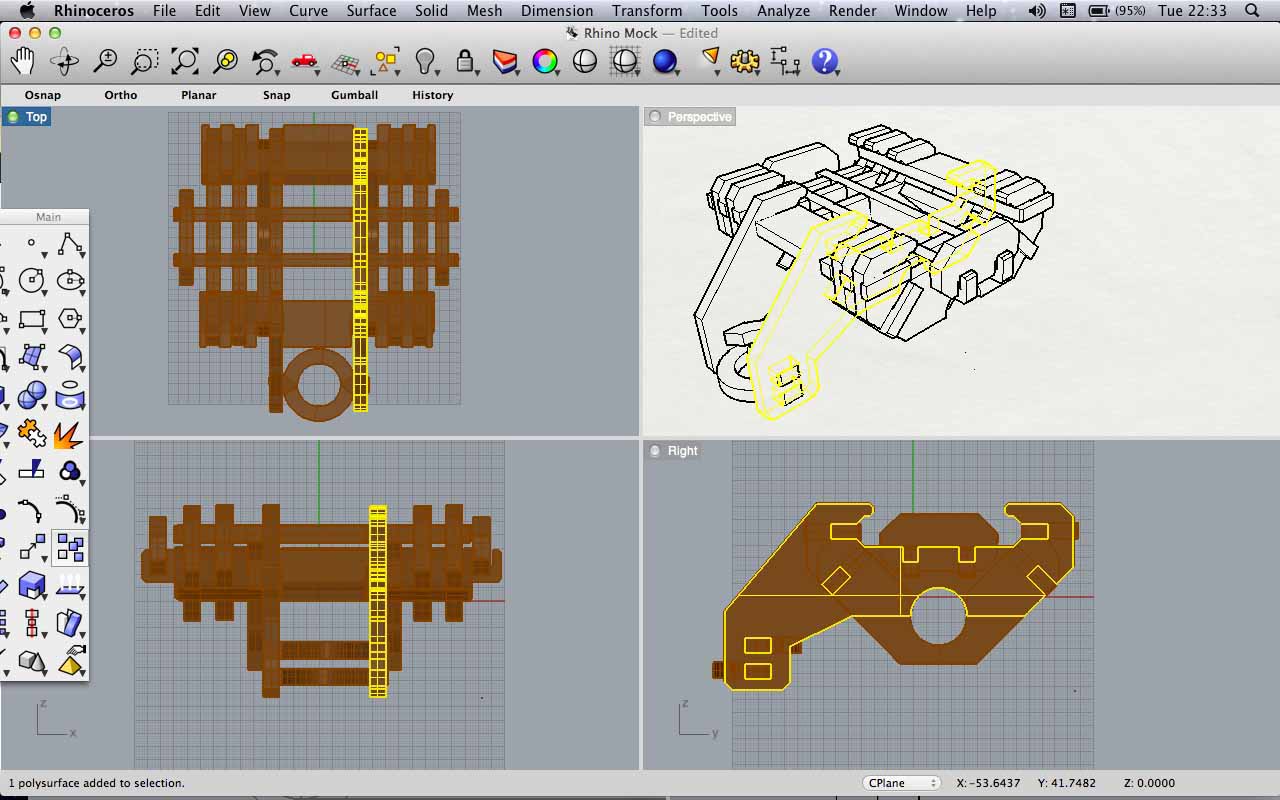
3D testing
I exported the drawings using the .dxf file type and then used Rhino to 3D model the drawing in such a way that I could see how well it aligned and fit together. Creating the project in virtual space before construction and printing will have saved me paper resources, time on the machine and redesign effot also. At some stage I would like to have a play with programs such as Catia, I understand this has the capacity to accurately measure forces, pressures and environmental conditions for structures.
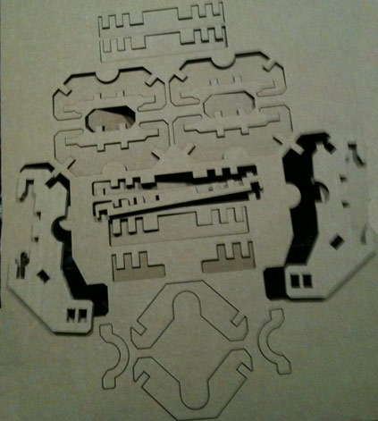
Laser Cutter
We used the laser cutter with 6.8 mm thick coragated card. At the time of printing this was different to the size that I had prescribed in my design, which was used a 6mm depth for each slot. I realsied that by using Illustrator I had missed the opportunity to use a parametric tool.
KEY RESOURCES:
Week 03 Class Lecture : Computer Aided Design
Week 03 Howework Review
Week 3 Blog Post : More than two Dimensions.