Week 08 : EMBEDDED PROGRAMMING
Overview
The assignment this week was to "measure something: add a sensor to a microcontroller board and read it". During Week 6 I had adapted and assembled the 'Hello World' FTDI board that contained a tiny44 microprocessor, an LED, a Tactil Switch and a Thermistor, it also had FTDI and ISP connectors. During Week 4 I assembled the 'FabISP' which houses another tiny44 microcontroller a usb connector and an ISP header. So for this week that leaves programming: A Tutorial from High-low tech explained how to use the tiny programmer (FabISP). The tutorial "explains how to use the TinyProgrammer, a small circuit board for loading code on the ATtiny44 and 85 microcontrollers (or other AVRs)".
A second tutorial by High-Low tech explained how to program using Arduino IDE. The Arduino IDE is a development environment that uses the C++ language but works with a lot of embedded libraries to simplify your coding. Finnaly the AVR microcontroller datasheet for the Tiny44 was a usefull source of infomation to understand the function and capacity of the microcontroller. I felt the best way to explain what i did was to write a step by step how-to: so here goes.
High-Low Tech : Using the Tiny programmerHigh-Low Tech : Programming an ATtiny w/ Arduino 1.0
AVR Tiny44 Microcontroller Datasheet
Settup
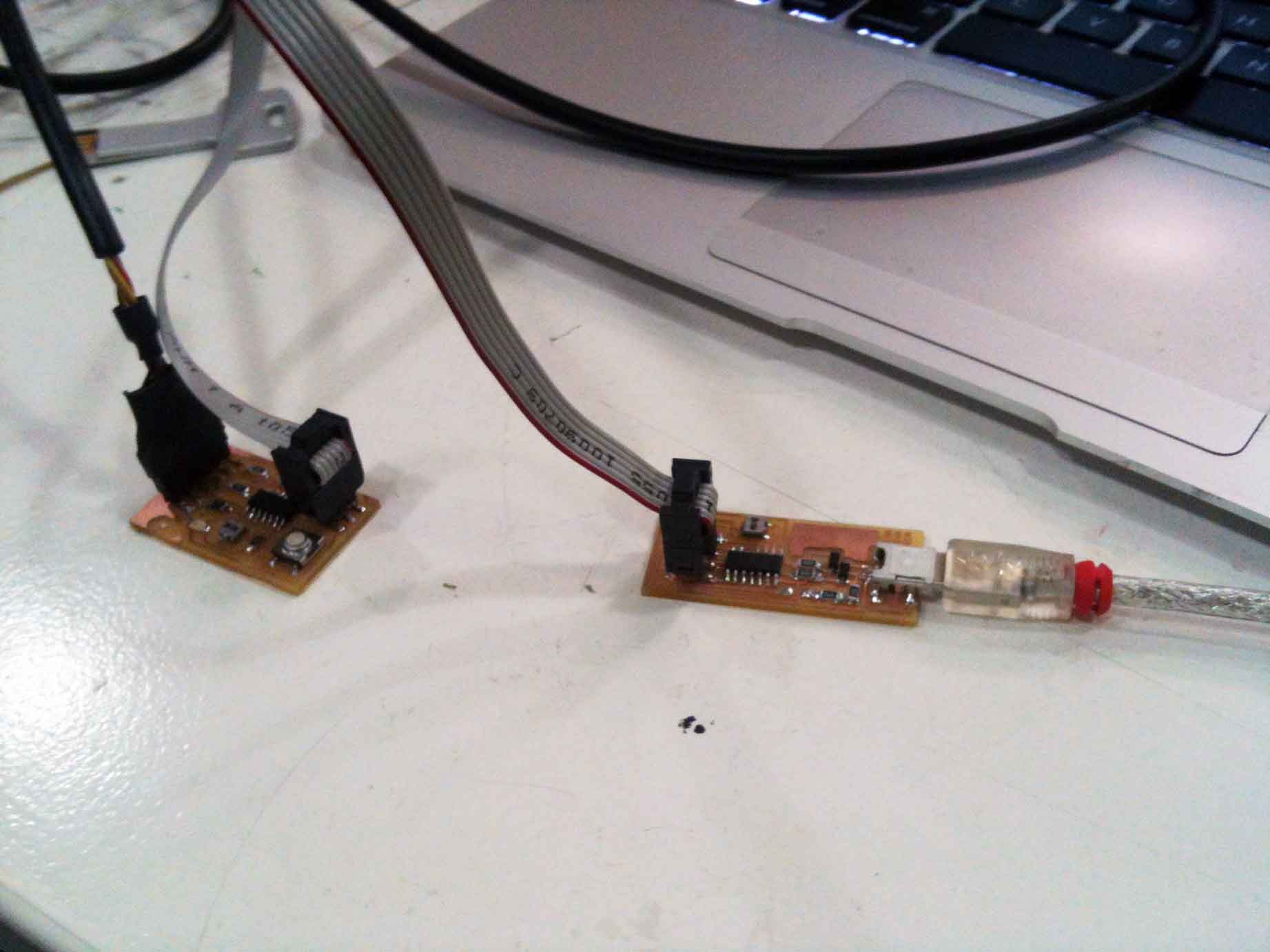
The FabISP connects to the computer through its USB cable connection (This also gives it power). The 'FabISP' then connects to the 'Hello World FTDI board' by the ISP headers common to both boards and a six-wire ribbon cable. The FTDI header of the Hello World board should be connected to provide power to the Atiny microcontroller. It is important to make sure that the Power ('VCC' in the circuit) and indicated by the red cable in the ribbon is connected correctly through both headers on both boards. (That is connecting MISO, MOSI, SCK, RESET, VCC, and GND pins of the FabISP header to the corresponding pins or the Hello World Board ISP) When this is done ... your ready to roll!
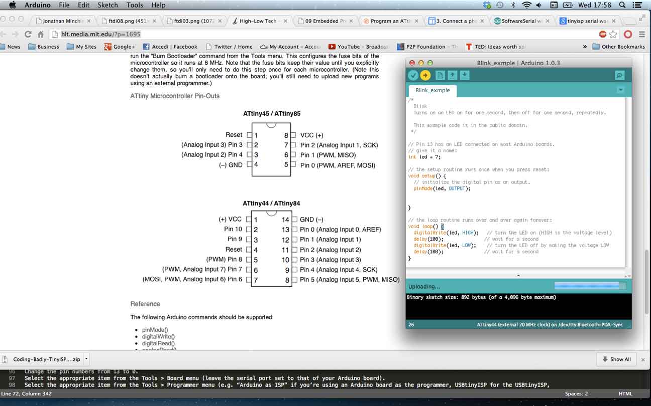
Using the FabISP programmer with Arduino IDE 1.3
NOTE :The Sketch is now setup with the correct hardware. Next a script can be transfered through the FABISP or AVRISP mk2 to the 'Hello World FTDI board'
Scripting (Blink example)
NOTE :The Microcontroller Pin numbers describe physical pins. Each of those pins corresponds to a function that which Arduino IDE uses. So in this case Microcontroller Pin 6 = (PWM, Anolog Input 7) Pin 7
Scripting Objective
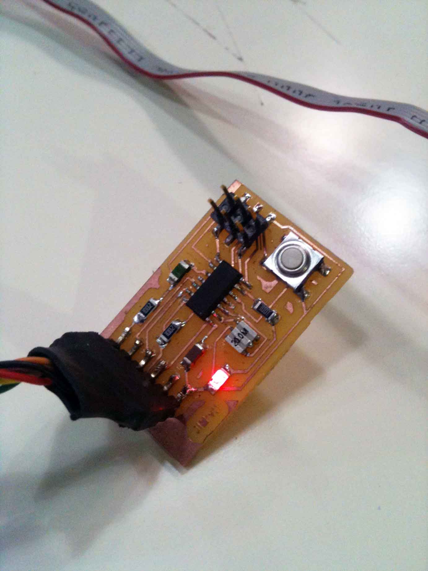
I have decided to create a script that Records the temperature and light up the LED when the button is pressed. I used the Academy tutorial as the base script to help me. Again I had to change the Arduino Pin Labels to match those of the Atiny44 and Hello World Assembly. To reiterate this process .. I connected the Button to the Atiny44 pin 5 which translated to Arduino Pin Label 8 (PWM Pin 8).
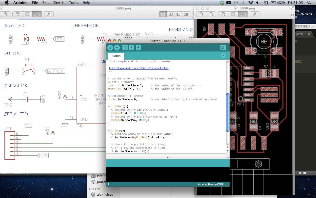
Problem 1
The First problem was that I needed a resistor between the microcontroller and the button. Pullup
Tutorial : Dojo Dave LED off until button pressedMicro processors, AVR ... one of the first Modern. a family of Microcontrollers. Pins vs dollars. Embedded Programming Tutorial By Chris Malcom.
KEY RESOURCES:
Week 8 Class Lecture : Embedded Programming
Week 8 Howework Review
Week 8 Blog : Ghosts and Bugs