Fab Academy 2013 |
|
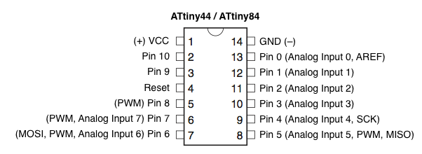
Embedded Programming: This week's assignment is to program the microcontroller on the board we created during Electronics Design through the ISP we created during Electronics Production and make it do 'something'. Since I added two LED's to my board, it was pretty clear what that something was. Blinking lights! Programming is somewhat of a crutch of mine, it's something I have trouble wrapping my head around. Luckily we could use Arduino. A mostly straightforward programming application that does a lot of work in the background that you'll never have to deal with. Of course Arduino is limited, but it will suffice for what I want the board to do. The board we created has a button, and an LED (two LED's in my case, a green and a red one). Arduino comes loaded with a lot of example 'sketches' that you can use. One of these is a Blink sketch. I loaded up the example, and uploaded it to my board to see what happened. Nothing happened. Turns out I still needed to change the line indicating that there was an LED attached to a certain pin. I pulled up the ATtiny44 datasheet and tried to figure out which 'number' was associated to a certain pin. After some fiddling I still couldn't figure out which pin was which and I ended up googling a little as well, ending up on this page, which had a comprehensive image akin to the one on the datasheet, but with a simple numbered pin list included as well.
In the Blink example, I substituted the preset pin for one of the pins I had an LED attached to, and uploaded the code to the microcontroller. Voila! I had a blinking light on my board. Off to a good start. I proceeded to add the second LED to the code, and then testing out the code with two blinking lights, which was also a success. One of the other examples built in to Arduino, is a Button example. This example has a button controlling an LED. I again changed the code to have the correct pin numbers and sent it off to the board. This also seemed to work after messing a little with the HIGH and LOW states of the voltage in the LEDs, and I successfully had a light going on as you pressed the button. The next step was to combine these two into one piece of code, and then to modify it for both LED's. I pasted some of the button code over to the blink code, and set the correct parameters. After a lot of trial and error (again mostly messing with the HIGH and LOW states) I seemingly had all the correct code in place, but it still wasn't woring properly. The red LED was always on, which was good, at the press of a button the red LED turned off and the green LED on. So far so good, except I had it programmed to have the green LED blink 10 times, turn again and the red LED on again. This wasn't happening. Turns out I had the code for blinking all set under the parameter of the button when it isn't pressed. There was never a chance for it to start blinking as it was quickly overruled by something else. After cutting and pasting that code into the part that decides what happens when the button is pressed, I suddenly had a working board: And here's the code I finally ended up using (you can also download the Arduino file on the Assignment Files page): /*
Blinky10
The RED LED is always on, at the press of a button it turns off
and the GREEN LED blinks ten times.
*/
// Pin names defined
int GREENLED = 3;
int REDLED = 8;
int buttonPin = 7;
int buttonState = 0;
int blinky;
// the setup routine runs once when you press reset:
void setup() {
pinMode(GREENLED, OUTPUT);
pinMode(REDLED, OUTPUT);
pinMode(buttonPin, INPUT);
digitalWrite(buttonPin, HIGH);
}
// the loop routine runs over and over again forever:
void loop() {
// read the state of the pushbutton value:
buttonState = digitalRead(buttonPin);
// check if the pushbutton is pressed.
// if it is, the buttonState is HIGH:
if (buttonState == HIGH) {
// turn RED LED on and GREEN LED off:
digitalWrite(GREENLED, LOW);
digitalWrite(REDLED, HIGH);
}
else {
// turn RED LED off:
digitalWrite(REDLED, LOW);
//and blink GREEN LED 10 times!
blinky = 0;
while(blinky < 10){
blinky++;
digitalWrite(GREENLED, HIGH);
delay(10);
digitalWrite(GREENLED, LOW);
delay(10);
}
}
}
Part 1 success! Of course, we were asked to try more than one programming language. In this case I decided to give Neil's echo a shot, so I downloaded the hello.ftdi.44.echo.c and hello.ftdi.44.echo.c.make file from the Embedded Programming page, using this image (from the same page) and this page as tutorials. Having already installed AVR Crosspack, I could immediatly start plugging in the fuse and make commands (given that I had the ISP and board properly connected). I ran into the same 'const' problem that I ran into during Electronics Production, which I also solved in the same way as back then. So far so good, no more errors and the program was successfully loaded onto the board by avrdude. Now to test it out! The echo program basically sends back what you send to it. If you type a letter, you get the same letter in return. A Python file is (term.py) is provided on the Embedded Programming page. Unfortunately, there was no response from the command, and it told me that there was 'No Module Named Serial', applied to term.py. Since the USB device is plugged in, there should've been an entry for it in /dev/ on my computer, but there didn't seem to be, lots of Bluetooth devices though. I tried getting the serial of the USB ports from System Profiler, and manually adding them to the python file, but this also didn't seem to do anything. Anna's tutorial shows that you can interface with the device through Arduino, so I jumped back into that application and found that it too couldn't interface with the device. After some Googling and some extra reading, I found that I had forgotten to install the FTDI drivers needed for the ATTiny device to show up. I downloaded the drivers and installed them, and immediatly saw the entry appear for the device under /dev/tty.usbserial-serialcodeofusb. Another step ahead! Python however, still wasn't having any of it. Just in case, I redid the whole fuse/make program procedure and still got no response fromPython. In Arduino however, I could now select the tty.usbserial device in Arduino under Tools>Serial Port). From there I could use the Serial Monitor option to have a window pop up that allowed me to send characters to the board, but there was no response. I hoped to have a very clear explanation as to how I figured out how to get this to work, but unfortunately I don't. I redid the fuse/make program procedure dozens of times, disconnected and reconnected the ISP and board numerous times, switched them from USB port to another one, rebooted the computer and none of it seemed to do anything. Until it finally did. There was no step that I did different as far as I could tell, but there it was. In Arduino's Serial Monitor, I sent a character, and it echoed it right back to me. What an adventure.  |