This week we're actually playing a small manufacturing line. Every student needed to make their own ISP in-circuit programmer. In this case the PCB design was already provided. We're kind of blindly making these, and then over the coming weeks we'll get into what we've actually made, and how it works.
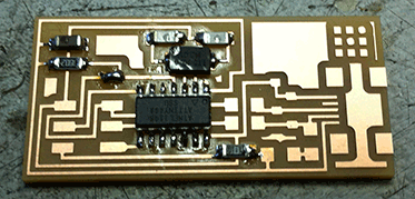
We started out by loading up the hello.ISP.44.cad file (found here) into the Fab Modules, and selecting the traces to be sent to the small milling machine. Our guru went through the settings and had us up and running fairly quickly. We loaded up one of the copper coated plates into the Modela and we used the Fab Modules to send the print. The Modela went on its merry little way, and a few minutes later we had our first milled PCB, which I quickly appropriated for myself.
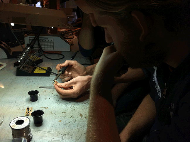
Of course, having the PCB is only the start. Now we move on to soldering. Having never soldered before, but being pretty good at tedious work I was looking forward to this. After a short explanation on how to properly solder onto the PCB I pulled up the board layout (this one) and used it to surround myself with all the correct capacitors, resistors and diodes (amongst things) and got to it.

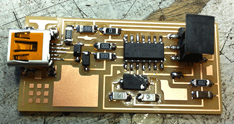
The soldering went swimmingly, and my PCB quickly started to look like an actual electronic board. I was able to pull of most solders in one go without getting too messy. Some of the solders weren't 'shiny' as was described in the tutorial, but adding a bit more usually fixed that without too much trouble.

A little under an hour later, I had a fully functional looking ISP, and ready to move on to programming the board for use.

I cut off a bit of ribbon and hooked those up to some connectors, to allow me to be able to connect two boards together. From there I hooked up the board to my laptop through the USB connector.
I unzipped the firmware (found here) and dove into Terminal in Mac OS X. Before I could actually get to work I actually had to install the AVR Crosspack because I didn't have XCode installed, so I could actually compile the firmware.
I then started plugging in the commands provided at the bottom of the assignment page.
Make Clean went off without a hitch, but I already ran into a problem with Make Hex.
In file included from usbdrv/usbdrv.c:12:0:
usbdrv/usbdrv.h:455:6: error: variable 'usbDescriptorDevice' must be const in order to be put into read-only section by means of '__attribute__((progmem))'
usbdrv/usbdrv.h:461:6: error: variable 'usbDescriptorConfiguration' must be const in order to be put into read-only section by means of '__attribute__((progmem))'
usbdrv/usbdrv.h:467:6: error: variable 'usbDescriptorHidReport' must be const in order to be put into read-only section by means of '__attribute__((progmem))'
usbdrv/usbdrv.h:473:6: error: variable 'usbDescriptorString0' must be const in order to be put into read-only section by means of '__attribute__((progmem))'
usbdrv/usbdrv.h:479:5: error: variable 'usbDescriptorStringVendor' must be const in order to be put into read-only section by means of '__attribute__((progmem))'
usbdrv/usbdrv.h:485:5: error: variable 'usbDescriptorStringDevice' must be const in order to be put into read-only section by means of '__attribute__((progmem))'
usbdrv/usbdrv.h:491:5: error: variable 'usbDescriptorStringSerialNumber' must be const in order to be put into read-only section by means of '__attribute__((progmem))'
usbdrv/usbdrv.c:70:14: error: variable 'usbDescriptorString0' must be const in order to be put into read-only section by means of '__attribute__((progmem))'
usbdrv/usbdrv.c:89:14: error: variable 'usbDescriptorStringDevice' must be const in order to be put into read-only section by means of '__attribute__((progmem))'
usbdrv/usbdrv.c:111:14: error: variable 'usbDescriptorDevice' must be const in order to be put into read-only section by means of '__attribute__((progmem))'
usbdrv/usbdrv.c:142:14: error: variable 'usbDescriptorConfiguration' must be const in order to be put into read-only section by means of '__attribute__((progmem))'
Okay, that looks confusing, but after some quick googling (and some help from our coordinator, Bas Withagen) I found out that the firmware was built in an older version of the code than what I just installed through AVR crosspack. The error message was actually fairly clear, in that all that I needed to do was dive into the designated files (usbdrv/usbdrv.h and usbdrv/usbdrv.c) and add 'const' to the variables. I wasn't initially sure where exactly I needed to add const, but with the same google search result I figured out that I had to add the 'const' tag in front of the lines that said PROGMEM. I quickly added it to all the variables that threw errors at me and ran Make Hex again, this time successfully.
Next up was Make Fuse. For this it notes to check the Makefile for the programmer setting. I opened up the Makefile and changed the AVRDUDE line from avrisp2 to usbtiny. The usbtiny being the chip used on the board. I plugged in Make Fuse and got another error.
avrdude -c usbtiny -p attiny44  -U hfuse:w:0xDF:m -U lfuse:w:0xFF:m
avrdude: Error: Could not find USBtiny device (0x1781/0xc9f)
Could not find USBtiny device. I had my suspicions that it meant that my ISP wasn't actually working, and after pulling in the coordinator again that was quickly confirmed. We used an electricity meter to see if the leads were all working. They weren't. Luckily we quickly spotted that one of the prongs of the Micro USB connector didn't seem to be fully connected to the board. An easy fix! I went back to the soldering iron and added a bit of extra soldering tin to the prong, and then checked the board again with the meter. Success, everything seemed to be working correctly now.
I plugged the board back into my computer and tried Make Fuse again, this time without a hitch.
At this point we were provided with another already functional ISP, which I also hooked up to my computer with USB. Using the ribbon cable, we also connect the already functional ISP to my newly soldered ISP. Then we run the final command, Make Program, which also ran its course without any problems.
This means I was completely successful in putting the program into my ISP, and that I now had a fully functional ISP. At this point, there was actually one more step to do. There were two jumpers added onto the board (one with an actual jumper, one with just tin) and after programming the chip these don't have any function anymore, so they could be removed. I used the heat gun to pull the jumper off the board, and then removed the tin that functioned as the other jumper.
As a test to see if it actually worked, we used my programmed ISP to hook it up to someone elses unprogrammed ISP to finish the Make Program step. This worked and soon everyone had their own working ISP's.
Week 4, mission accomplished!
