12. Input devices
This week I learn about input devices.
Group assignment - probe an input device’s analog levels and digital signals
Individual assignment - measure something: add a sensor to a microcontroller board that you have designed and read it
Hero shot of the week
 Reading a CO2 sensor with a PCB that I made
Group assignment
I used an Arduino Uno board to read a DHT11 digital temperature sensor, and my ATtiny44 board to read analog signals from an MG811 CO2 Sensor.
DHT11 temperature sensor
The DHT11 is a low-cost digital temperature and humidity sensor. It uses a capacitive humidity sensor and a thermistor.
I pasted the following code.

For the code to compile, we need to import DHT.h which is a library for DHT sensors. Go to ‘Sketch’ > Include Library > Library Manager and type in DHT, then click Install. Since I had this library installed previously, I skipped this step.


I pressed Upload, and received an error.
Sketch uses 5048 bytes (15%) of program storage space. Maximum is 32256 bytes. Global variables use 243 bytes (11%) of dynamic memory, leaving 1805 bytes for local variables. Maximum is 2048 bytes. An error occurred while uploading the sketch
avrdude: ser_open(): can’t open device “\.\COM4”: The semaphore timeout period has expired.
Problem uploading to board. See http://www.arduino.cc/en/Guide/Troubleshooting#upload for suggestions.
I checked that the right port where the Arduino connects to the computer, is selected, and press Upload once more to flash the program.

However I still encountered the following error
Arduino: 1.8.13 (Windows Store 1.8.42.0) (Windows 10), Board: “Arduino Uno”
Sketch uses 5048 bytes (15%) of program storage space. Maximum is 32256 bytes. Global variables use 243 bytes (11%) of dynamic memory, leaving 1805 bytes for local variables. Maximum is 2048 bytes.
An error occurred while uploading the sketch
If the program is flashed successfully, the software should say Done uploading.

Next we clicked on Serial Monitor at the top right-hand corner.


The temperature and humidity are printed on the serial monitor at regular intervals.

To probe the signal, I connected the probe to the signal wire connected to digital pin 4 and the aligator clip to a GND connection Arduino.

I set the CH1 voltage interval to 1V and played with the probing interval.

It appears that the sensor communicated with the Arduino at 40Hz.
MG811 CO2 Sensor
This analog sensor is purchased for my final project. I hooked it up to the PCB used for my individual assignment. Details about the programming can be found in the Individual assignment section.


Its peak signal is about 50mV, although to be honest, this is not the signal I was hoping to see. We could be seeing noise here. When I try to blow into the sensor, the voltage does not change very much, but it could be due to signal lagging.
GH-718C Mini PIR Motion Sensor
Wiring

Code
/*
 * PIR sensor tester
 * Author: Adafruit
 */

int ledPin = 13;                // choose the pin for the LED
int inputPin = 2;               // choose the input pin (for PIR sensor)
int pirState = LOW;             // we start, assuming no motion detected
int val = 0;                    // variable for reading the pin status

void setup() {
  pinMode(ledPin, OUTPUT);      // declare LED as output
  pinMode(inputPin, INPUT);     // declare sensor as input

  Serial.begin(9600);
}

void loop(){
  val = digitalRead(inputPin);  // read input value
  if (val == HIGH) {            // check if the input is HIGH
    digitalWrite(ledPin, HIGH);  // turn LED ON
    if (pirState == LOW) {
      // we have just turned on
      Serial.println("Motion detected!");
      // We only want to print on the output change, not state
      pirState = HIGH;
    }
  } else {
    digitalWrite(ledPin, LOW); // turn LED OFF
    if (pirState == HIGH){
      // we have just turned of
      Serial.println("Motion ended!");
      // We only want to print on the output change, not state
      pirState = LOW;
    }
  }
}
Individual assignment
For my final project, I would need
- a pressure sensor to measure the pressure inside the fermentation chamber, and
- a CO2 gas sensor
- a temperature sensor
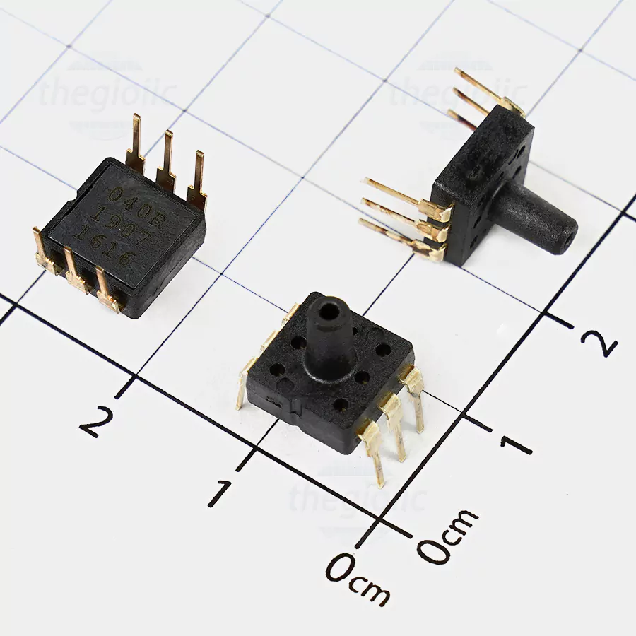
I obtained a MPS20N0040D-D pressure sensor. Link to datasheet However, upon receiving it I realized that MPS20N0040D-D is a through-hole type and I should have gotten MPS20N0040D-S which is the SMD version. It can measure up to 40kPa.
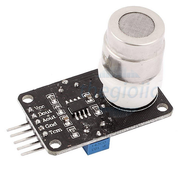
As for the CO2 gas sensor, a local store sells MG811 CO2 Sensor Module at a price of $28 a piece, while from China it costs $18.
While waiting for the CO2 sensor to arrive, I thought of designing an ATtiny44-powered board that allows flexibility of adding any sensors via 02x02 headers.
PCB Design
I designed a board in KiCAD as shown.

Electrical rules check showed no errors, I then continued to assign footprints and generate a netlist.
All was going well when an error suddenly came up.

I went back to Eeschema, right clicked on the Attiny and select ‘Edit footprint’. That launched the Footprint library browser where I clicked on Fab before double-clicking on ‘SOIC-14_3.9x8.7mm_P1.27mm’. That seems to resolve the issue even though I still did not get the root cause. In the first place, the software already shows the correct foot print which is ‘Fab:SOIC-14_3.9x8.7mm_P1.27mm’.


This time, I succeeded to load a netlist without any problems.


My board is now ready for milling.

Milling
I used a 20-degree V-bit to mill the traces and a 1mm corn-teeth end mill to cut out the PCB.

Stuffing
Here is our simple shopping list for this week


Firstly, I secured the board with an aligator clip and went on to place the chip in position.
Since I didn’t have flux at the time of soldering, the solder quality is terrible.

After I finished soldering all the components, I did a continuity check with a multimeter to make sure every connection from the ATtiny’s legs to the headers is sound, and that GND and VCC are not shorted. My board is now ready for programming.

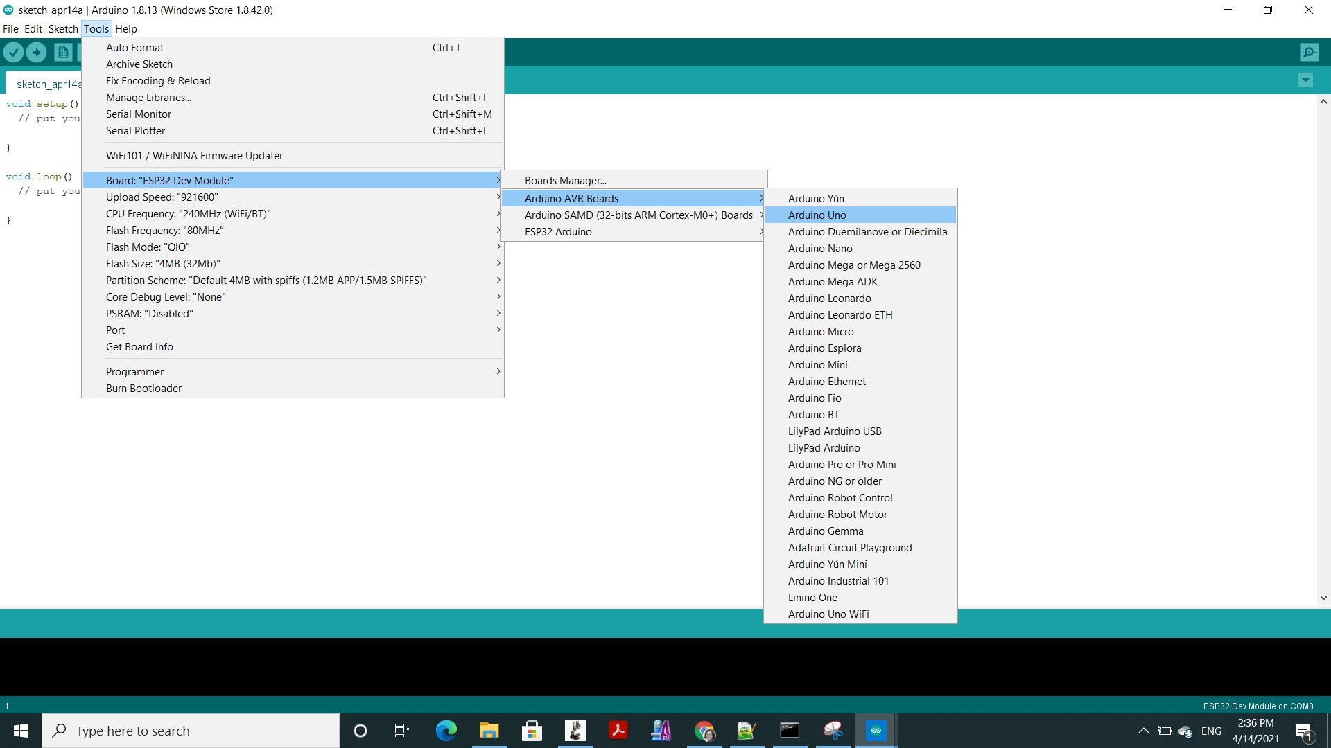
Using Arduino Uno as a programmer to add a bootloader
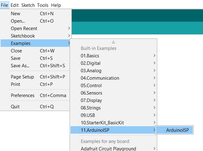
Launching Arduino IDE, I needed to load a sketch called ArduinoISP by going to File > Examples > 11.ArduinoISP and selected ArduinoISP. This opened a new sketch.
- Processor: Arduino Uno
- Programmer: AVR mkll
I pressed Upload to send the ArduinoISPU sketch to the Uno. It was successful.
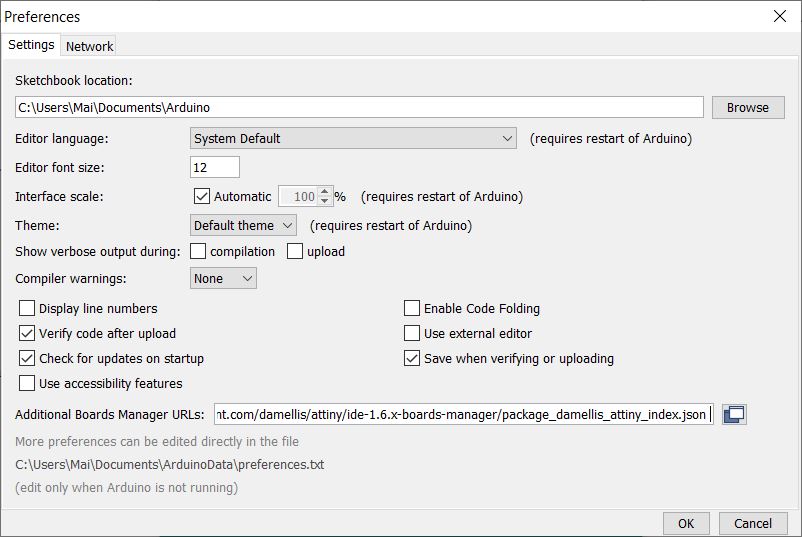
I clicked on Preferences and in the field next to Additional Board Manager URLs, I pasted the following link and pressed OK. https://raw.githubusercontent.com/damellis/attiny/ide-1.6.x-boards-manager/package_damellis_attiny_index.json
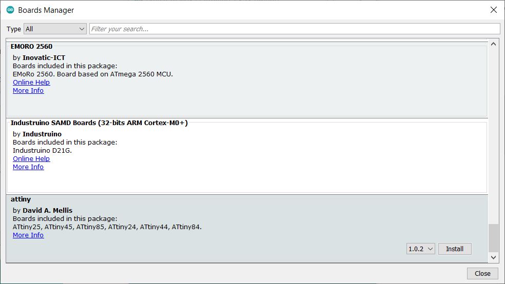
In Tools > Board > Board Manager…, I scrolled all the way down until I found Attiny and clicked Install.
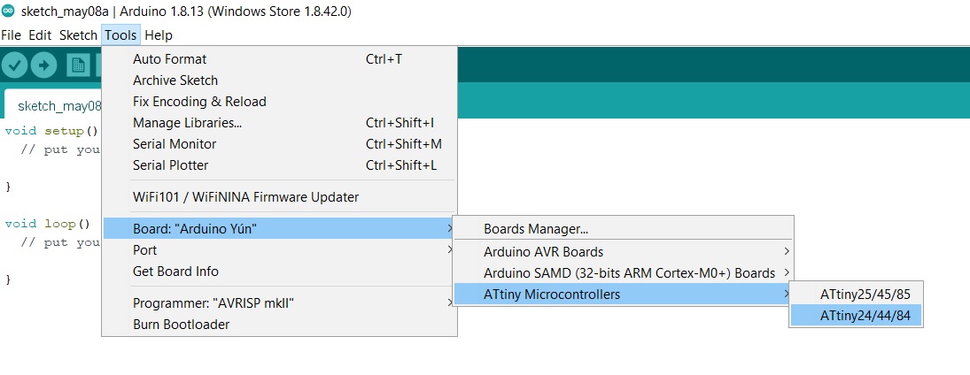
Going back to Board, I clicked on ATtiny microcontrollers and selected the ATtiny24/44/84 family.
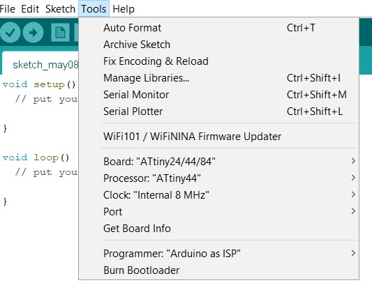
The rest of the Tools setting is as follows
- Processor: ATtiny44
- Clock: Internal 8MHz
- Programmer: Arduino as ISP
Before we could turn Arduino Uno into a programmer, there is some wiring to do:
- wire the SCK, MISO, MOSI and RST pins on my board to the Arduino Uno’s pin 13, 12, 11 and 10 respectively.
- add a 10uF capacitor between the RST and GND pins on Arduino Uno (the negative side of the capacitor going to GND). This will prevent the Uno from resetting itself which starts the bootloader.
However, since I do not a 10uF on hand, I used a 33uF capacitor instead.
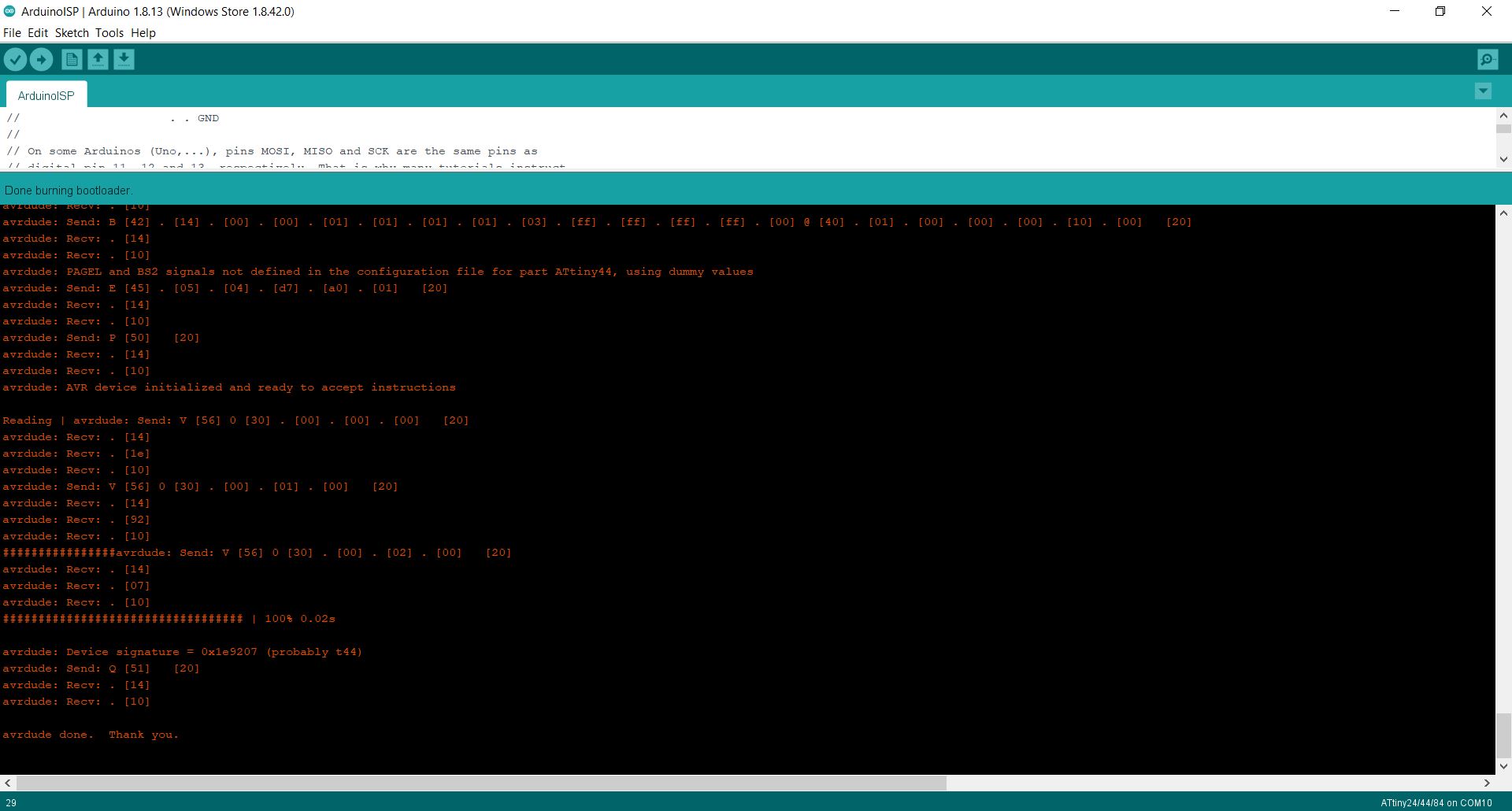
Now all is ready to buuuurn (the bootloader, of course). When done, the IDE will tell you Done burning bootloader.
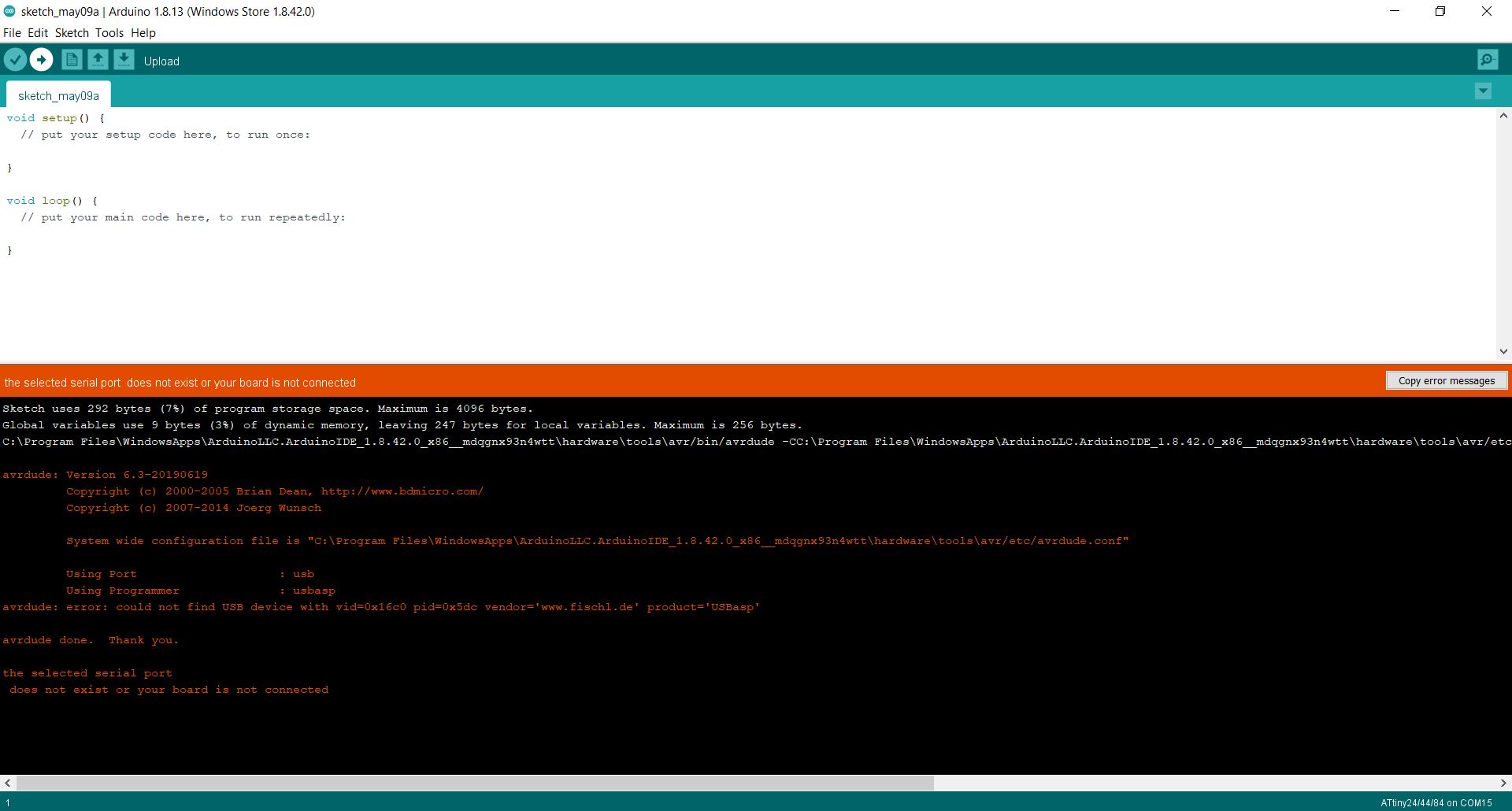
Although the bootloader was succesfully burnt, I could not proceed to upload a sketch to the ATtiny. Whenever I did, different types of errors came up. For example:
Serial port does not exist
Programmer not responding

Invalid device signature

Please check your wiring connections and continuity if you encounter any of the above errors.
Eventually I managed to upload a sketch.

How I resolved it was… that I had a hunch and decided to press down on the chip and click the Upload button as I continued holding it down. Surprisingly that worked immediately. While this is a happy ending, it also means that my milling and/or soldering is unreliable and can be vastly improved.

A list of errors encountered while using ArduinoISP
Error: Serial was not declared in this scope (when uploading ArduinoISP sketch)
Cause: I selected the ATtiny44 in Board when it should be Arduino Uno.

Error: avrdude: stk500_recv(): programmer is not responding
avrdude: stk500_getsync() attempt 1 of 10: not in sync: resp=0x03 … avrdude: stk500_getsync() attempt 10 of 10: not in sync: resp=0x66 Error while burning bootloader.
Causes: There could be several
- Failure to upload the ISP sketch to Arduino before burning. See report here. It’s the same for me.
- Failure to secure the chip in the socket. See report here

Error: avrdude: Expected signature for attiny44 is 1E 90 07
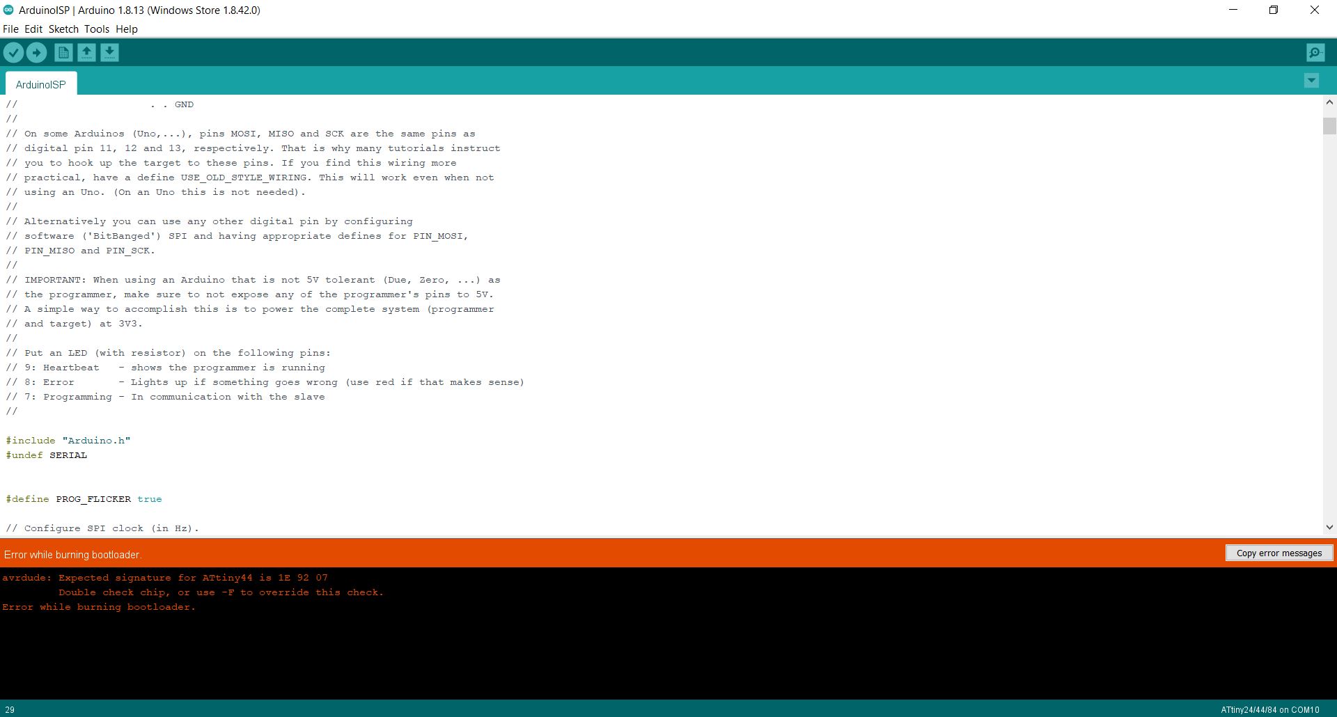
Error: avrdude: Yikes! Invalid device signature
Cause: There could be several
- Reset wired to Ground. See report here
- MISO connection was not well secured in my case.

Error: avrdude: usbdev_open() Did not find any USB device “usb” (0x03eb/0x2104)
Cause: There could be several
- “ArduinoISP” was selected instead of “Arduino as ISP” for the programmer choice. See report here.
- Connection

Wiring
There are 4 pins on the MG811: VCC, GND, D0 and A0.
To know which analog input pin on the ATtiny should be connected with MG811 sensor’s A0 output, I referred to this handy pinout mapping from a Fab Academy tutorial.
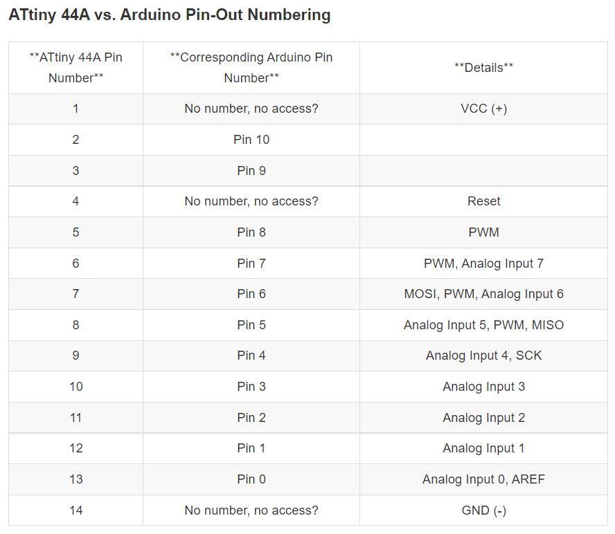
I connected A0 pin to ATtiny44’s pin 10 or Analog Input 3, but you can also use other pins such as pin 11-13.
Programming
Sample code for MG811 sensor
The code below should be used with the CO2Sensor library which is available for downloading here.
// Sensor CO2 MG811
// Source: https://navody.dratek.cz/navody-k-produktum/detektor-oxidu-uhliciteho-co2-mg811.html

#include "CO2Sensor.h"
// create a sensor instance from the library,
// the first parameter is the connecting pin (A0),
// the second parameter is the inertial coefficient (0.99),
// the third parameter is the number of measurements at each reading (100)
CO2Sensor co2Sensor(A0, 0.99, 100);

void setup() {
  // initial serial communication
  Serial.begin(9600);
  // calibrate
  co2Sensor.calibrate();
}

void loop() {
  // read CO2 concentration from sensor to variable
  int value = co2Sensor.read();
  // print value
  Serial.print("Concentration of CO2: ");
  Serial.print(value);
  Serial.println(" ppm.");

  // if the value is higher than 1000, print a warning for the user
  if (value > 1000) {
    Serial.println("Exceeded safe concentration of 1000 ppm, ventilate!");
  }

  // pause before a new one during the loop
  delay(1000);
}
I was supposed to calibrate the sensor before use by exposing it to a clean-air environment for at least 48 hours. Since time is lacking, I proceeded without calibration.
Having installed the CO2Sensor library, I successfully ran the above code with an Arduino Uno. Below is the serial monitor output.

At first, the value always stays at 399 ppm, even when I exhaled on it. However, the next day, the value climbs to over 1800 and then 2600 ppm. I suspected that calibration must be performed before the read value can be meaningful.
Unfortunately, when I compiled the program for ATtiny44, two unexpected errors came up.
Serial.h was not declared in this scope

This is because the ATtiny does not support UART. Instead, we had to use SoftSerial library.
Error compiling for board ATtiny24/44/84: sketch too big

As it turned out, the ATtiny does not have enough memory for the computation specified by CO2Sensor.h so I could not use this library. In fact, I simplified the program to just read the analog input.

Simplified code
// Sensor CO2 MG811

#include "SoftwareSerial.h"
const int rx=1;
const int tx=0;
int analogPin = 3;
int inertia = 0.99;
int tries = 100;

SoftwareSerial mySerial (rx , tx);

void setup() {
  // initial serial communication
  mySerial.begin(9600);
}

void loop() {
  // read CO2 concentration from sensor to variable
  int value = analogRead(analogPin);
  // print value
  mySerial.print("Level of CO2: ");
  mySerial.print(value);
  mySerial.println(" mV.");

  // pause before a new one during the loop
  delay(1000);
}
I was able to compile and uploaded this sketch to ATtiny board, also using Arduino as ISP.
Wiring and reading CO2 sensor
The sensor was powered and read through a USB-UART adapter. I made sure that TX from ATtiny44 connects to RX on the adapter.

The serial output shows the sensor’s readings in milivolt.

Useful links
- Fabacademy assignment by Gleb Bulygin - Input devices
- Comparing a photodiode and a phototransistor
- Program an ATtiny44/45/84/85 With Arduino
Files
- Arduino code for reading DHT11 sensor
- Arduino code for reading PIR sensor
- PCB Design
- Arduino code for reading MG811 sensor