5. Electronics production
This week I made the first attempt at milling PCB in my life. I have used a CNC machine before but not for making PCB.
Group assignment
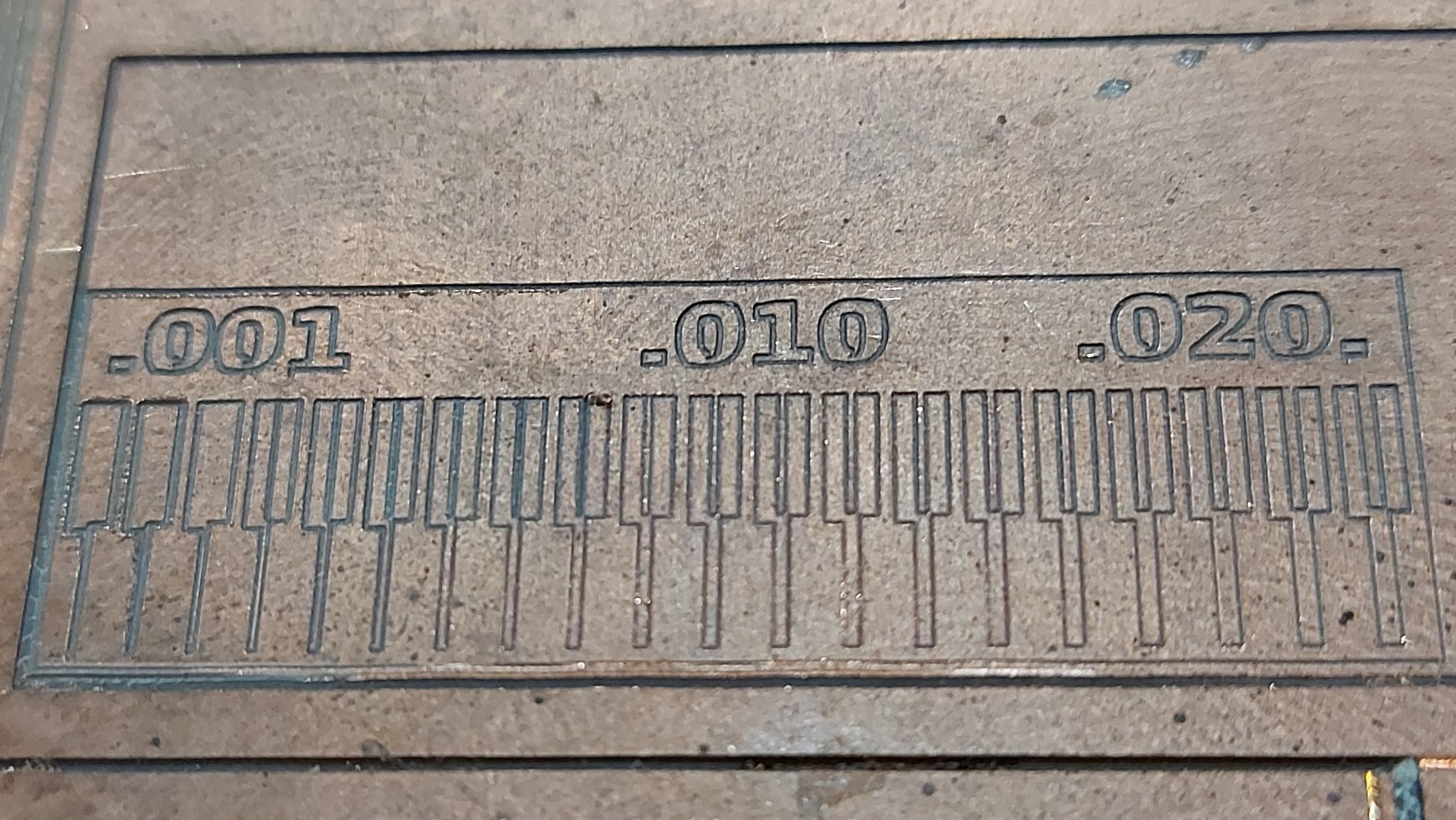
- characterize the design rules for your PCB production process
Individual assignment
- make an in-circuit programmer by milling and stuffing the PCB, test it then optionally try other PCB processes
Hero shot
Group Assignment
To fulfill this exercise, I am going to mill Fabacademy’s linetest pattern and observe the trace qualities and optimize milling parameters.
Introducing our CNC beast
This is an overkill for PCB, I know. This machine could handle aluminium.
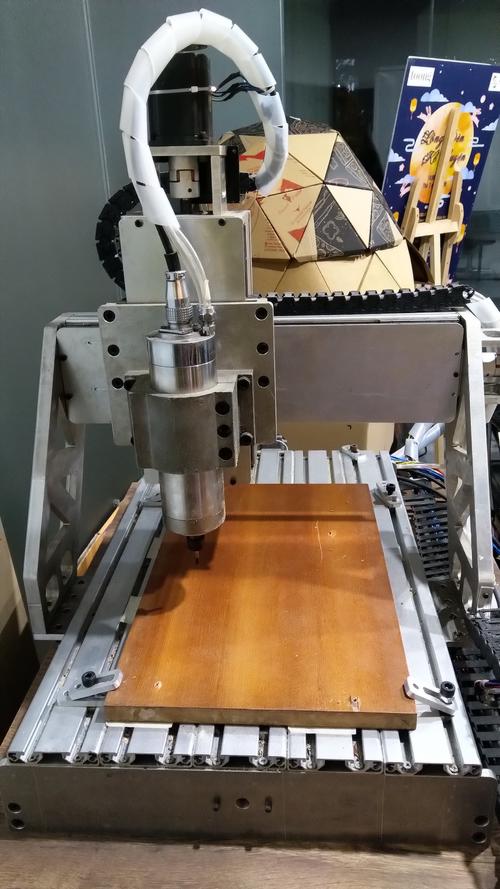
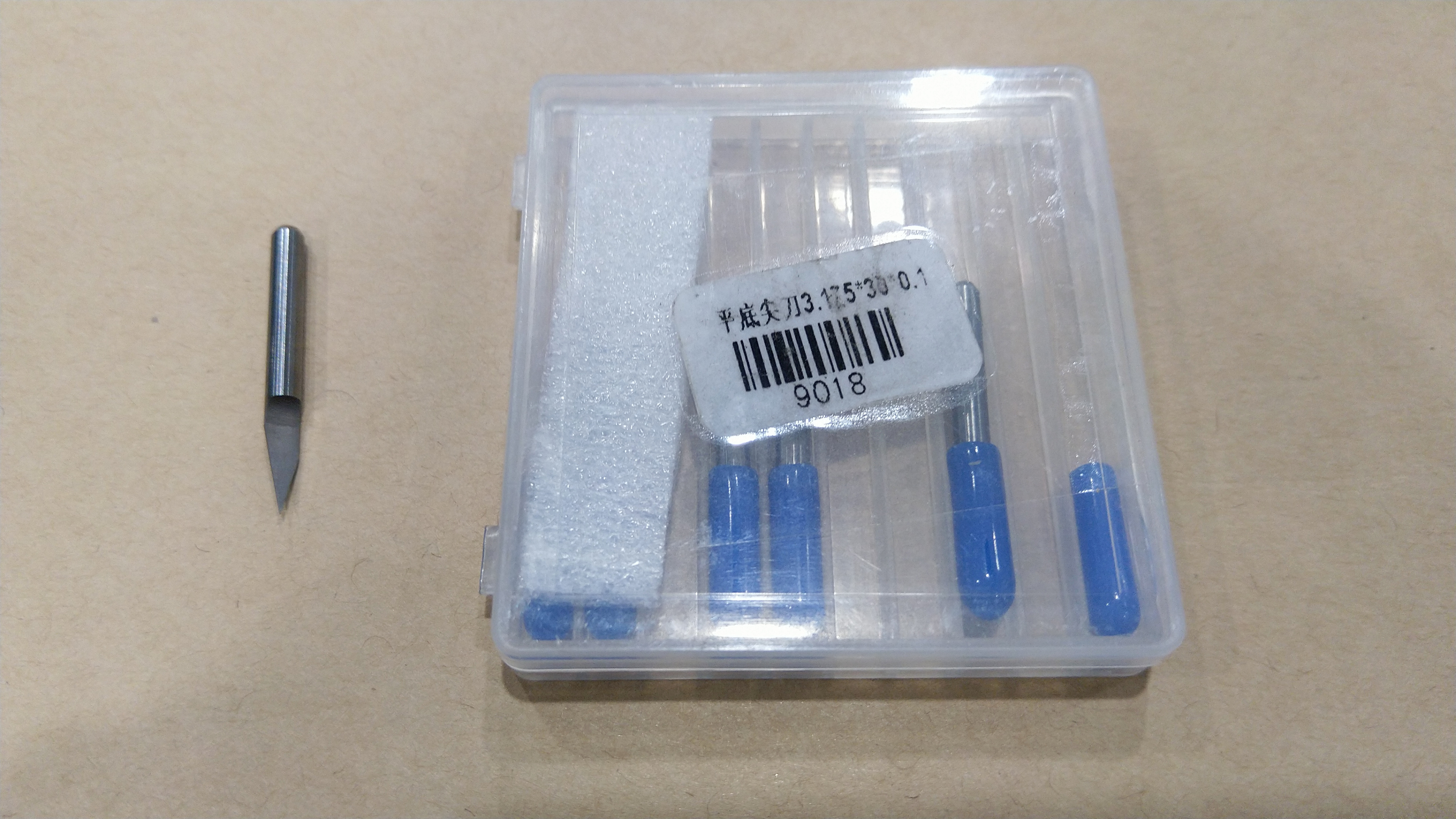
Since the smallest end mill available in our lab has diameter 4mm, which is too big for milling PCB, and some 20 and 30 V-bits with 0.1mm tip at the moment, I decided to go ahead and try a 30-degree V-bit .
Exploring MODS
The first thing I did was going through Fabacademy’s MODS tutorial to gain an overview of the process.
I downloaded [Fabacademy’s test pattern]which consists of two parts:
inner pattern, and
and a cut-out pattern


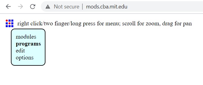
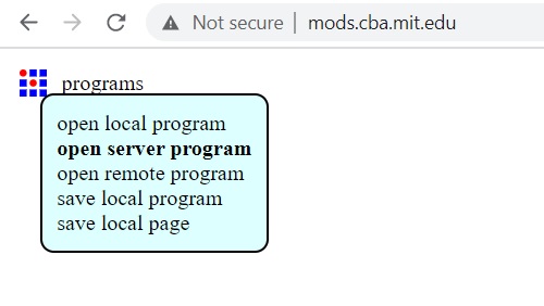
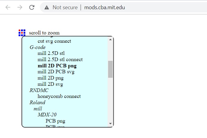
I opened MODS by typing in mods.cba.mit.edu in my browser.
For milling the outline, I set the tool diameter to 0.004 inch or 0.1mm, cut-depth of 0.004 inch and max depth 0.004 inch and leave default settings for feed rate, plunge rate and spindle speed.
Once I press Calculate, a .nc file popped up asking to be saved to the computer. Later I changed its format to .gcode so that it can be imported to our CNC software called Mach3.
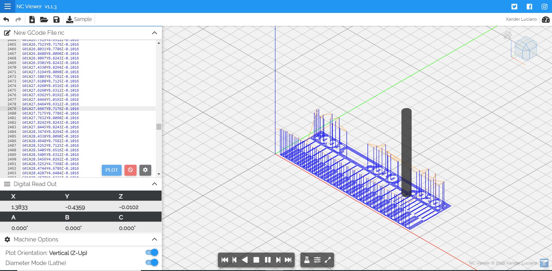
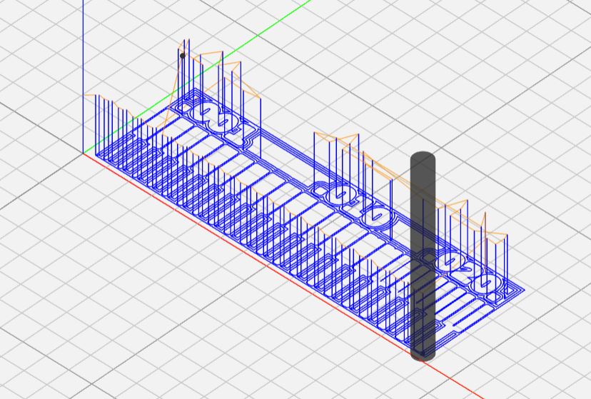
To visualize the milling path, I started an Easel project and imported gcode. It says gcode is invalid. I found an alternative viewer at https://ncviewer.com and tried it instead.
Open the gcode file generated earlier and the g-code commands will appear in the left-hand panel, and select Diameter Mode.
Advancing to MODS interface, some questions popped up
- what is the difference between basic diameter and tool diameter.
- are there recommended feed rate and plunge rate settings? Are they determined by trial and error? Or can they be calculated for each combination of material and tool?
Looking further around MODS, I realized that it does not support V-bit which is a downer, since our lab only has a 4mm flat mill and some 20 and 30 V-bits with 0.1mm tip. Being optimistic, I joined a Global Open Time session and asked if MODS has a secrete v-bit milling feature that I was unaware of. Luckily, Adrian Torres tipped me off that a previous student named Japopo Dimatteo was clever enough to create a MODS program for v-bit milling, which I hope to explore.
Below I will explain how to use our CNC machine.
Steps to use the CNC machine
1. Start the machine
Our CNC machine is controlled by Mach3 software.
After launching the software and connecting to the CNC controller via a USB cable, Mach3 prompted me to press Reset.

I pressed Reset, and the status changed to Device Ready.

Now the machine can be jogged with configured System hotkeys.
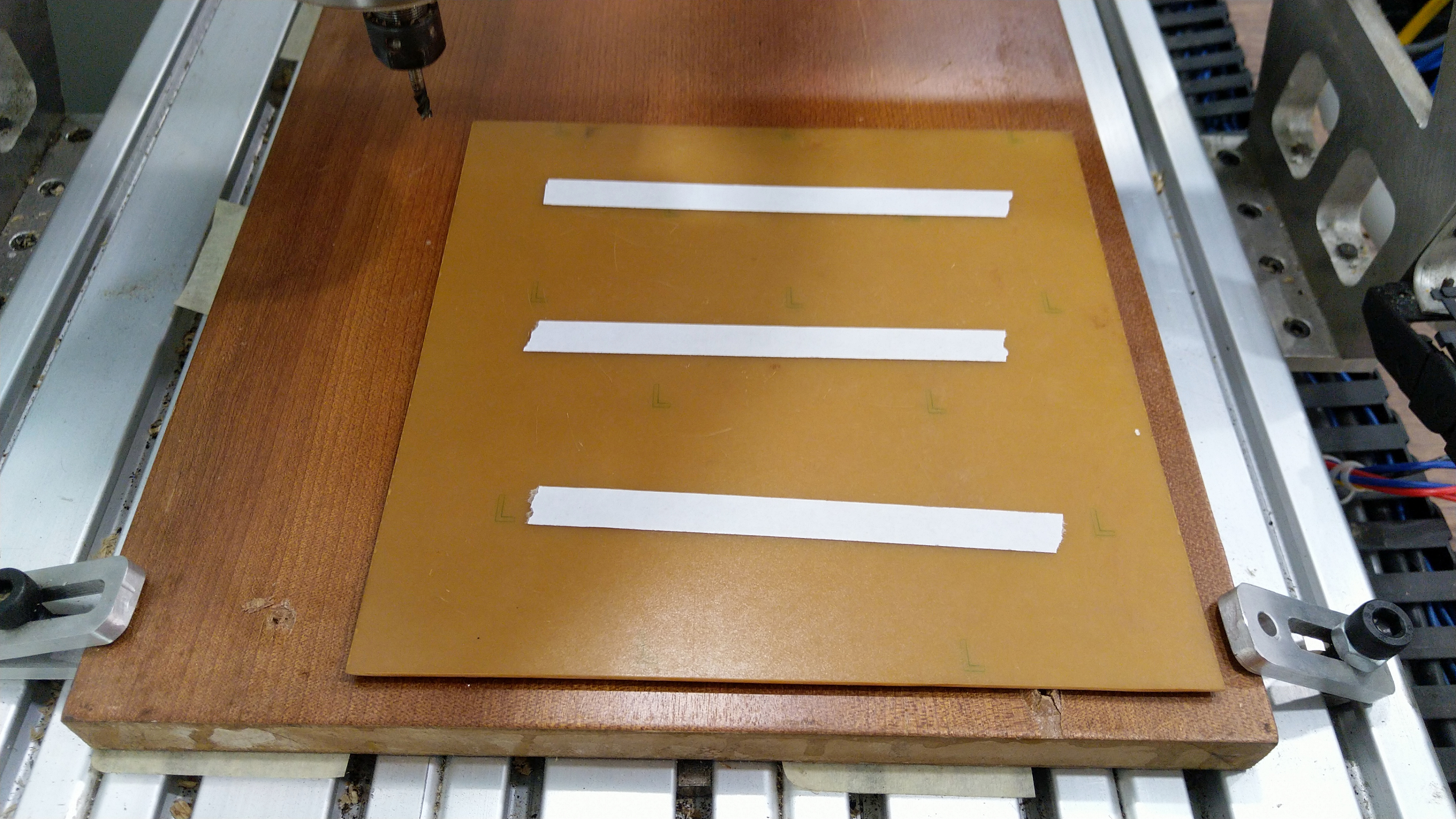
2. Set up the workpiece
A waste board is already clamped to the machine. I mounted the FR1 board on it with double sided tape and checked that it is secure and flat.
3. Mount the V-bit in spindle
Using jog mode, I moved the spindle to an appropriate height in order to install a 3mm collet and mount the V-bit.
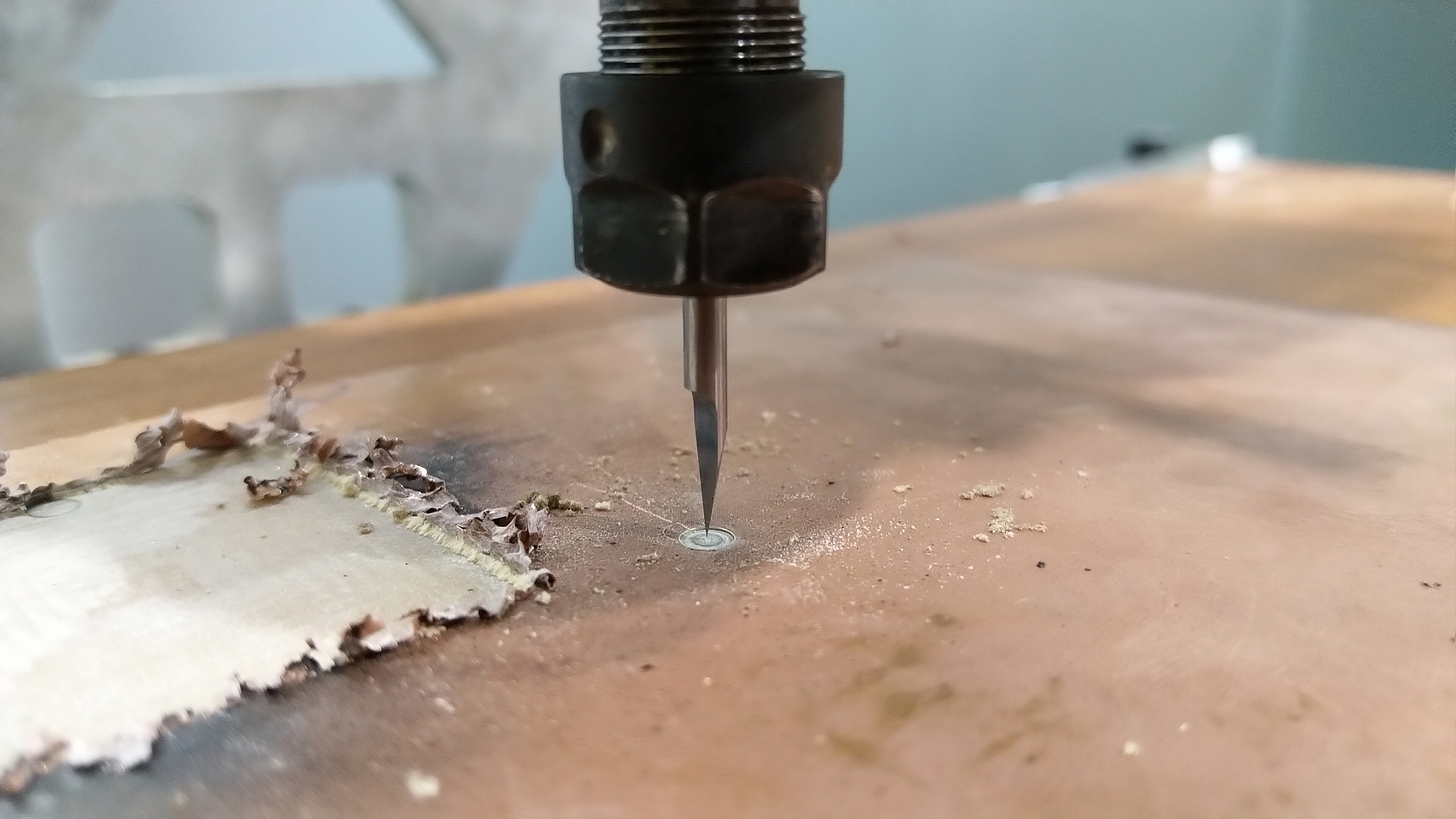
4. Set a zero position
I jogged the machine to where the V-bit is almost touching the FR1 board and pressed Zero X, Zero Y and Zero Z. Using spanners, I loosened the collet such that the V-bit dropped to the board surface and tighten the collet.
5. Prepare the gcode to check surface leveling
Before milling the actual thing, I want to make sure that the work area is more or less flat, since V-bits are sensitive to uneven surface. Besides, I am scared of breaking bits.
I drew a simple rectangle in Easel, a browser-based software that I already knew since my early days of playing with Shapeoko. The rectangle is about the size of the PCB. The idea is by observing the engraved boundary of the rectangle, I can tell how slanted is the work area and may be able to adjust or compensate accordingly. The starting depth of cut is 0.1mm and can be increased if necessary.
Here are the settings I used for the job:
I followed Easel’s recommended settings for milling PCB:
- feed rate 254 mm/min or 4.23 mm/s
- plunge rate 228.6 mm/min or 3.81 mm/s
- depth per pass 0.4mm or 0.0157 in

Easel allowed me to export the g-code file.
6. Load gcode in Mach3 interface
I pressed the Load G-Code button to input the g-code file generated by Easel earlier.

The code appears on the left-hand panel.
7. Run, machine, run
Next, I pressed Cycle Start, and watched the spindle ramp up the speed before plunging into action. Check out a video of the machine carving the rectangle here
At the end, I am relieved that V-bit did not break from the get-go. One side of the carved rectangle does look deeper than the opposite side, which means that the board is not exactly level. However it does not look so bad to the point where the V-bit can get into troubles.
Subsequent milling attempts
It took me a few rounds of lowering starting depths to ensure that the tip cuts into the copper layer. I also realized that the board not completely level. At first, only about 1cm towards the left-hand side corner is engraved, the rest did not show up.
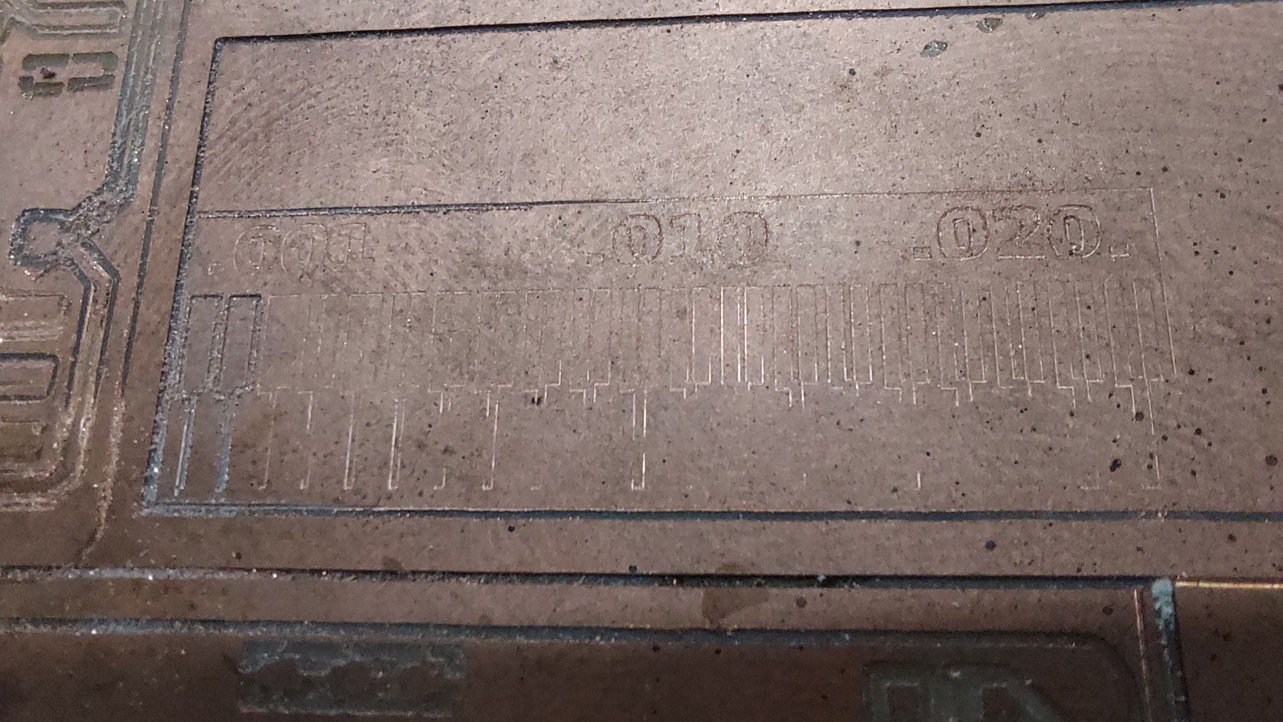
I had to set a lower starting depth 5 times, before the entire pattern was fully engraved.
Individual Assignment
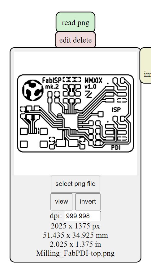
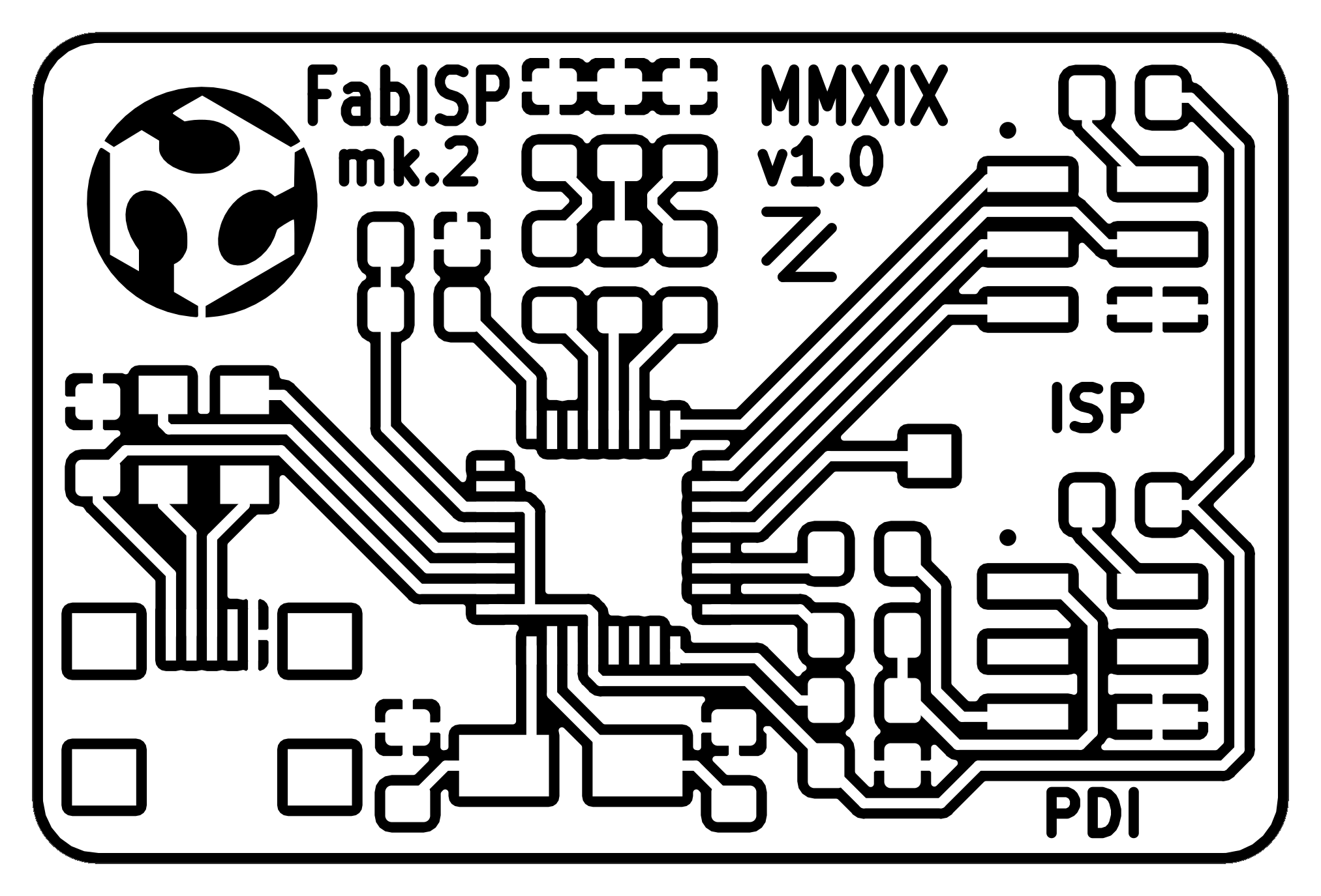
To make FabTinyISP, I would need an Attiny44 or 45 chip. Since they are unavailable in Vietnam, I opted to make an ISP with Atmega16U2 as per Zaerc’s design. I downloaded the following pattern from Zaerc’s Github.

Check Jacopo’s v-bit program
Since the program only accepts SVG inputs, I proceeded to obtain the SVG files from Zaerc’s Github.
I followed Easel’s recommended settings for milling PCB:
- feed rate 254 mm/min or 4.23 mm/s
- plunge rate 228.6 mm/min or 3.81 mm/s
- depth per pass 0.4mm or 0.0157 in
Some issues I spotted with this program:
- The depth of cut values keyed into Set PCB defaults module are not copied into mill raster 2D module. I
- Calculate function only outputs a file the very first time after you load in a design file. Subsequent changes of parameters will not generate a file, so you need to refresh the browser, and start a new every time.
- It would be helpful if the last-used parameters can be saved for future use.
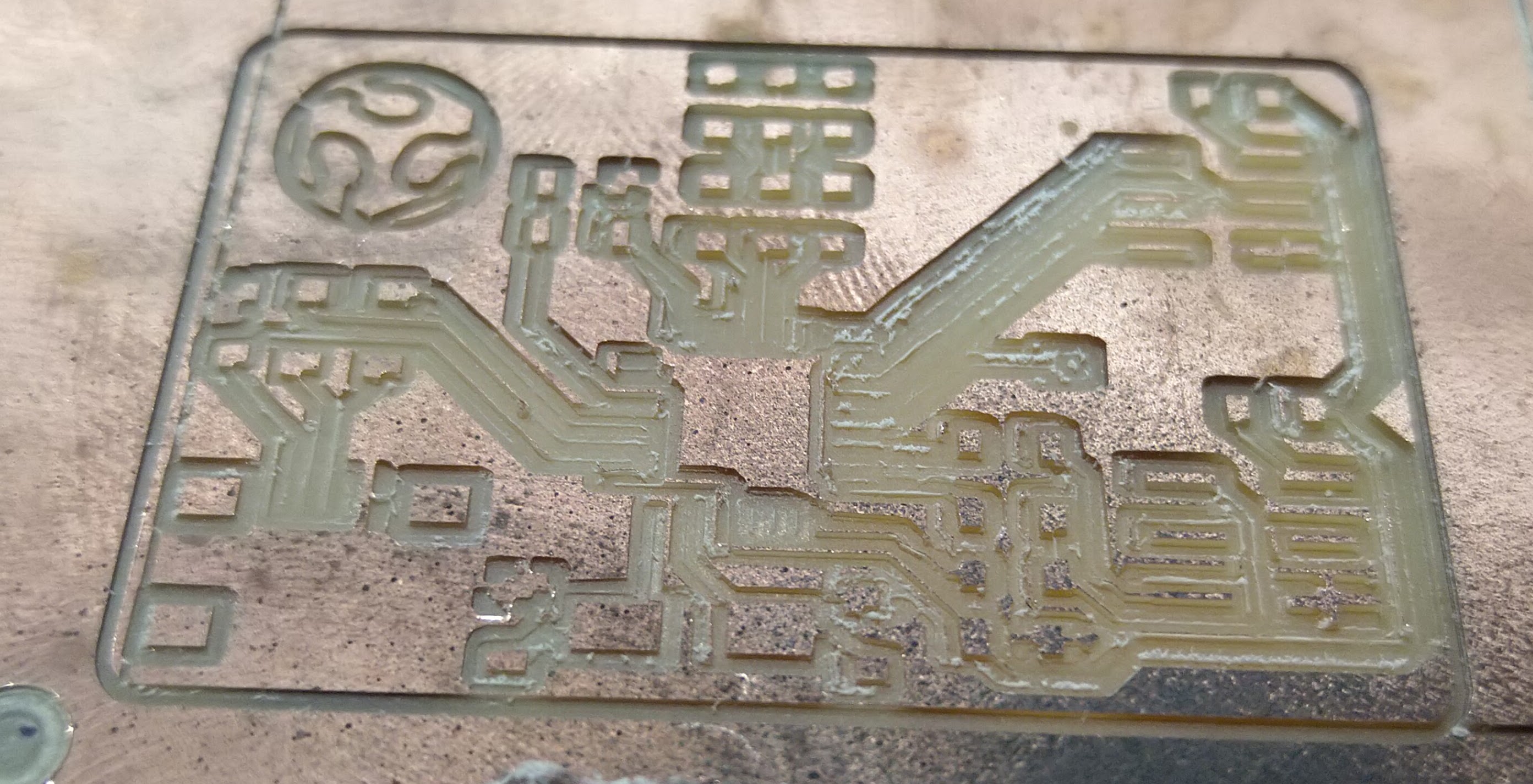
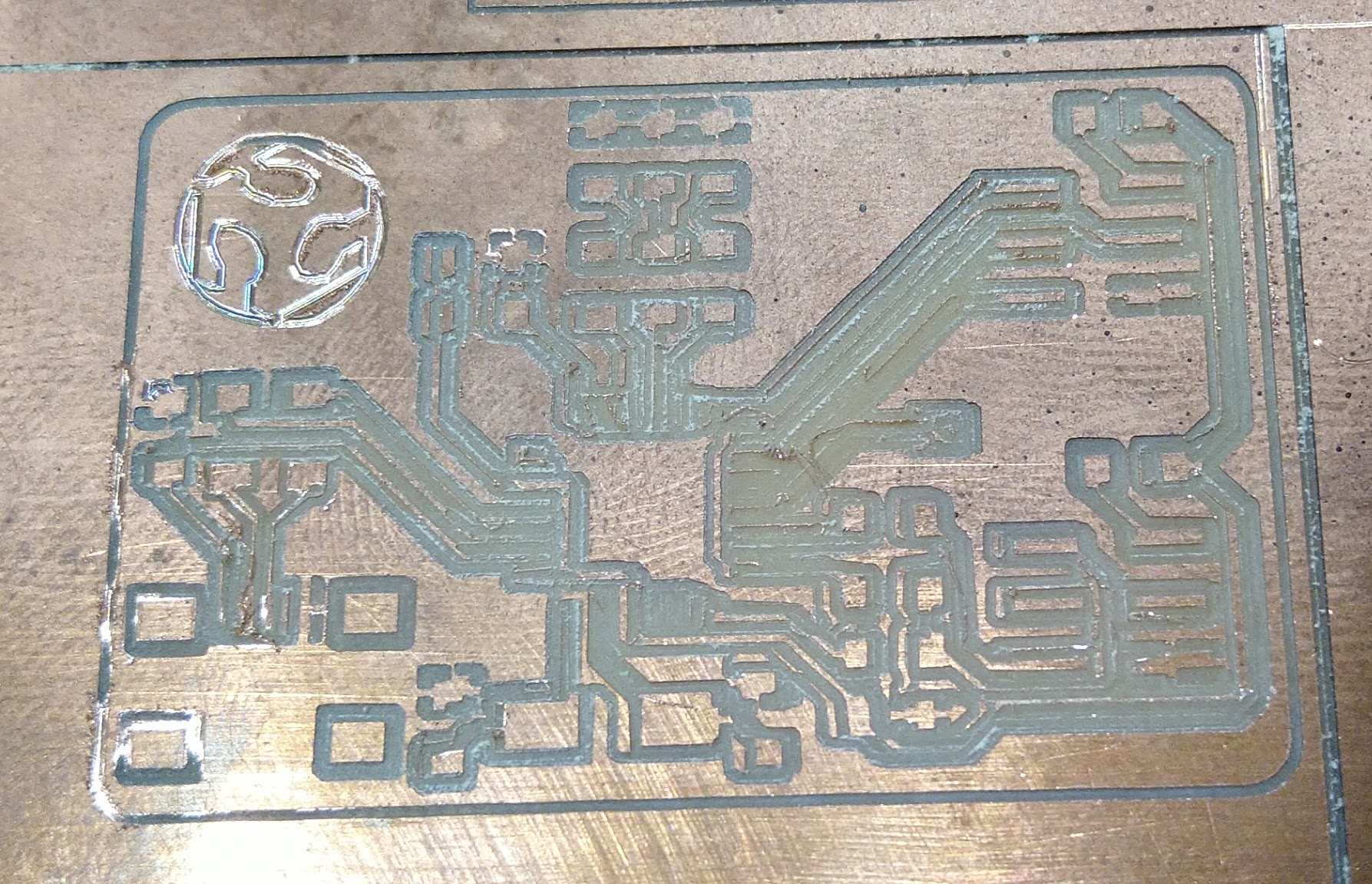
First PCB ever milled
This is my first attempt. At 0.3mm depth of cut, it carved too deeply and destroyed some traces.
You can see a video of the machine running here
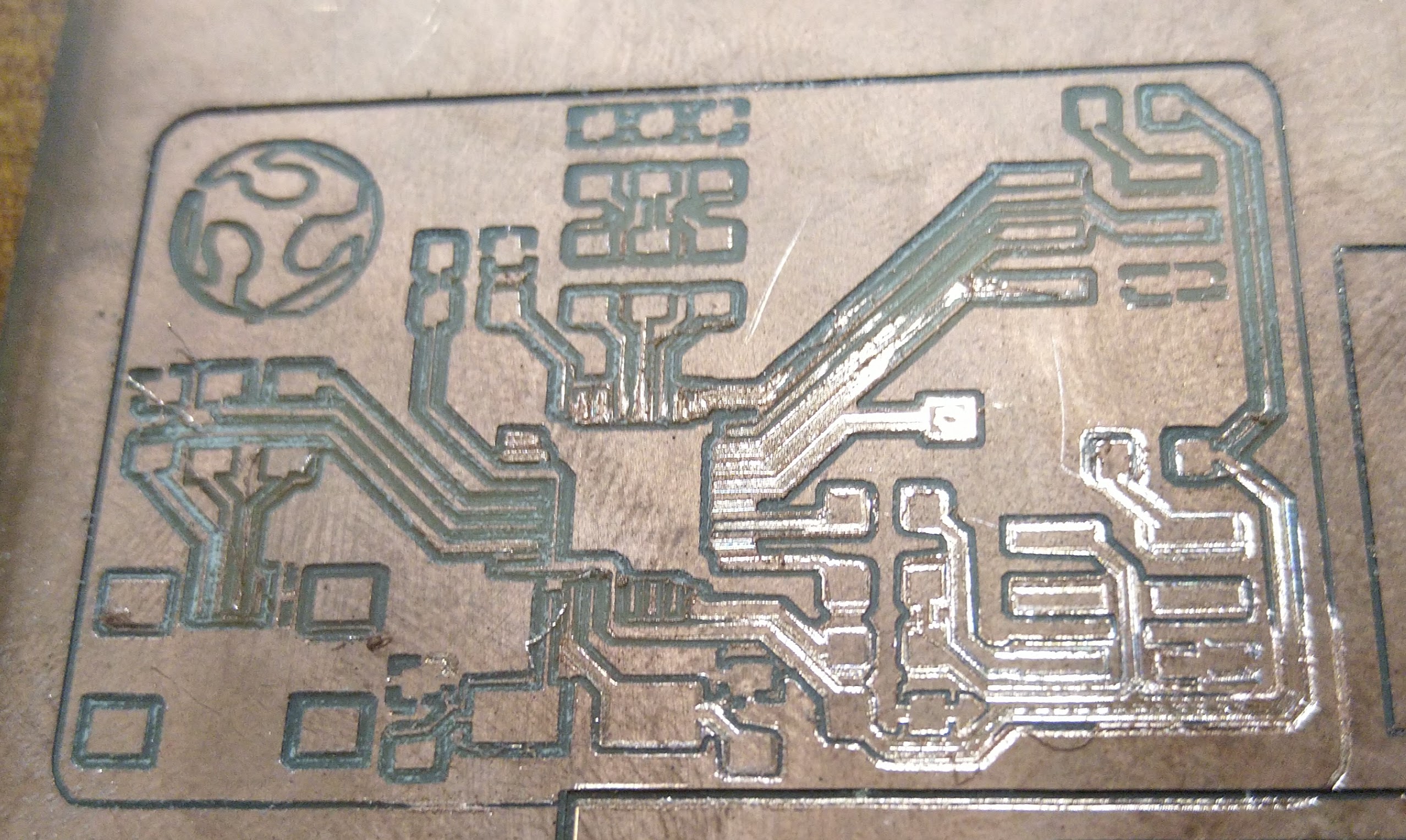
Second attempt
On the second attempt, I reduce the depth by 0.2mm. It looks better but many traces were still grazed to the ground.
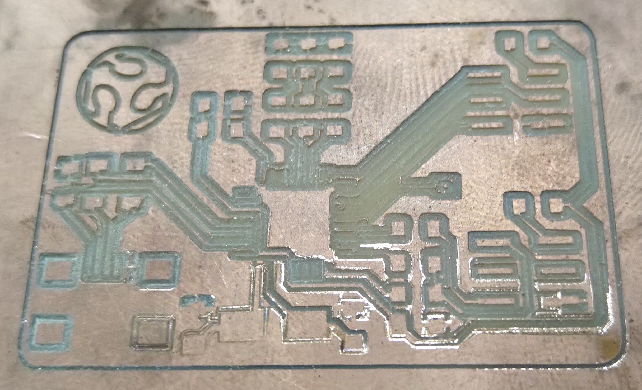
Third attempt
This time, the bit only went down by 0.1mm into the material. There are clear improvements but much of the traces are still lost.
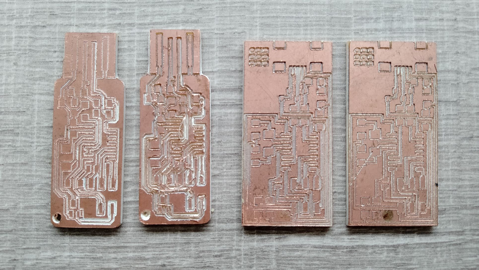
Forth attempt
The bit only went down by 0.02mm into the material. The result is much better but I am still not there yet.
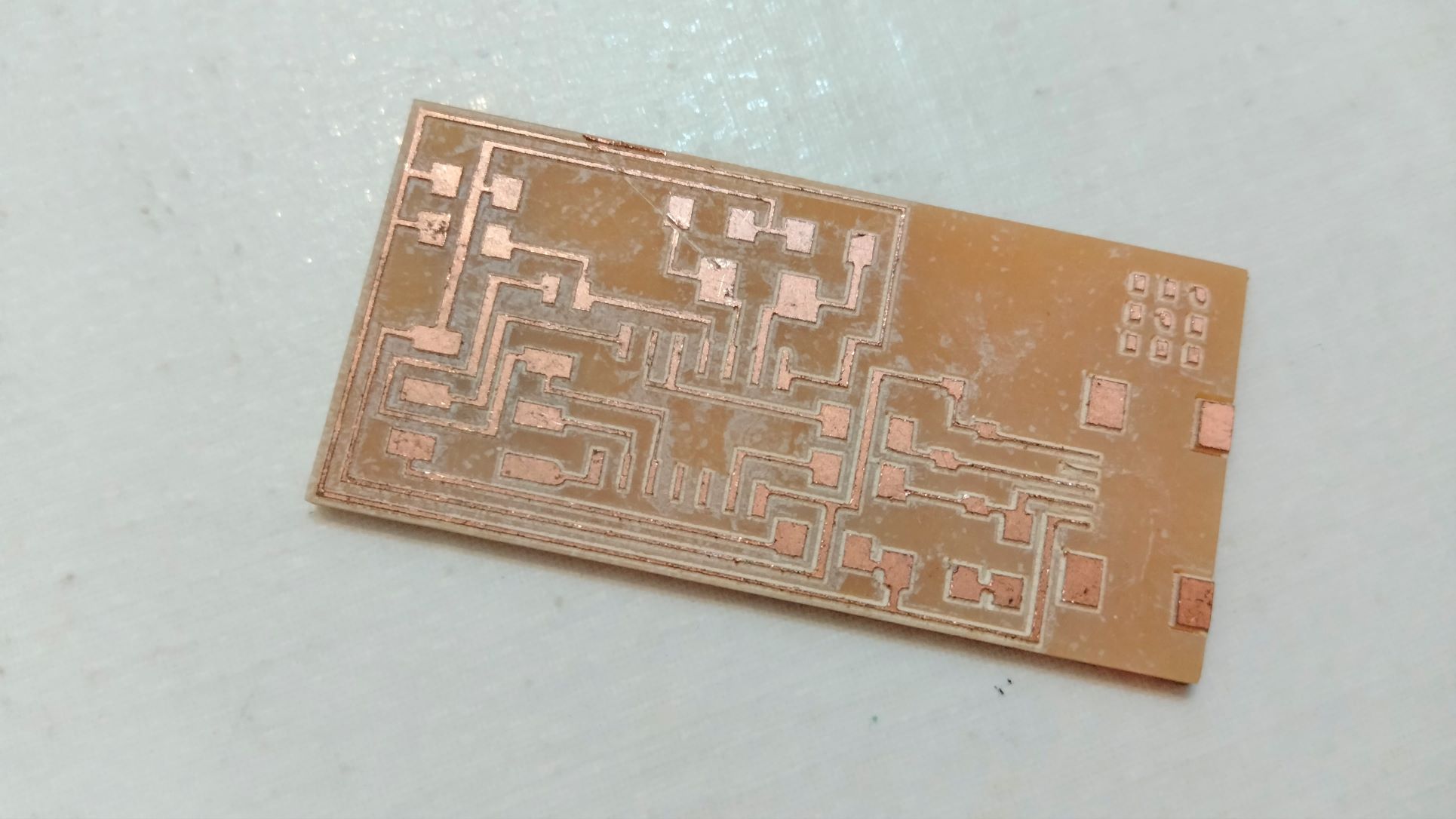
… I lost count of how many more attempts after that, but eventually I got something decent, or at least usable. The two on the left are [FabISPkey(http://fab.cba.mit.edu/content/archive/projects/fabispkey/index.html), and on the right, HelloISP.
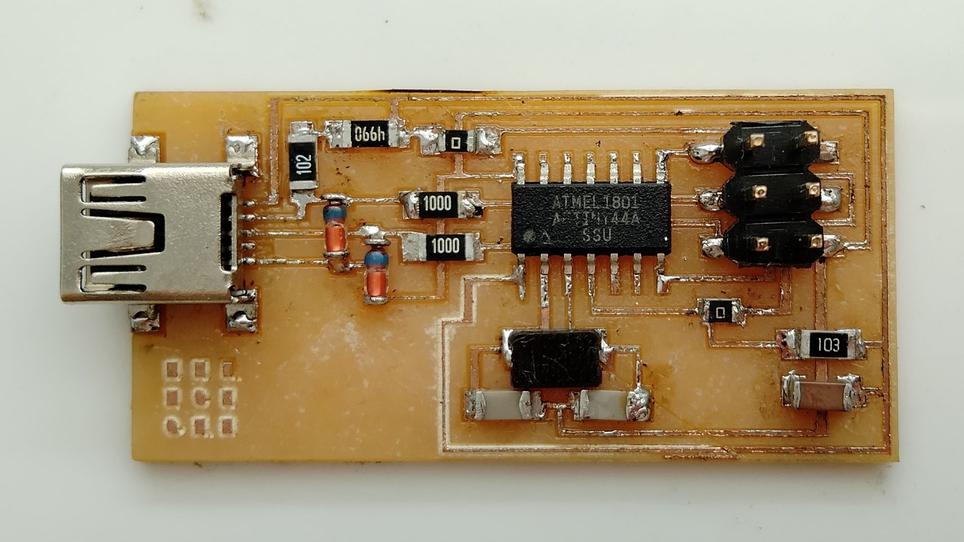
Soldering Hello.ISP.44
Bill of materials
Copper Board D1 = 3.3v Diode = The line inscribed on the casing indicates the orientation of the cathode D2 = 3.3v Diode R1 = 1k Resistor R2 = 499 Resistor R3 = 100 Resistor R4 = 100 Resistor R4 = 100 Resistor R5 = 10k Resistor IC1 t44 = Micro-controller 20MHz = Resonator J1 ISP = the 6 point socket type that the board type is named after C1 1uf = Capacitor of 1 (u)micro (f) farad SJ1 = Jumper 1 = A part of the circuit to be cut after the micro controller has been programmed SJ2 = Jumper 2
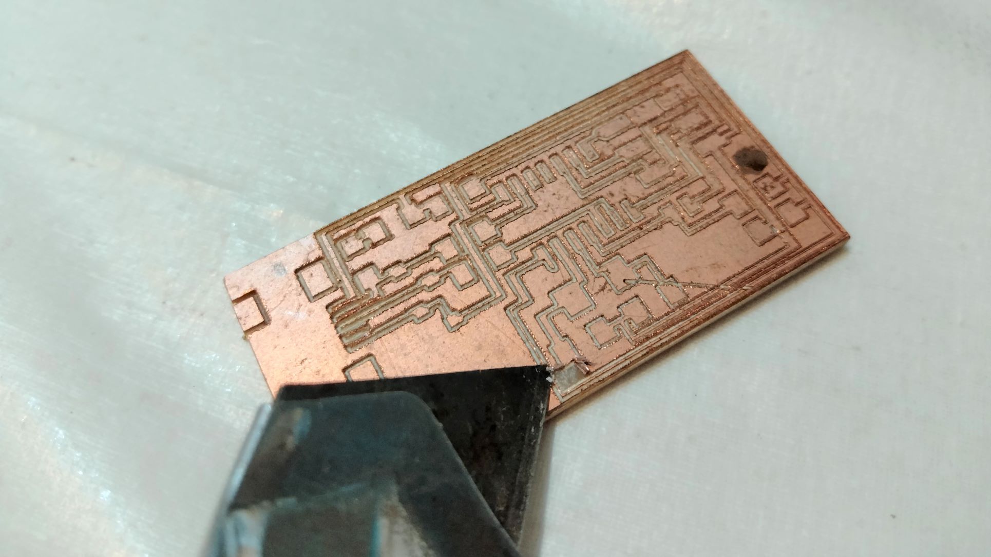
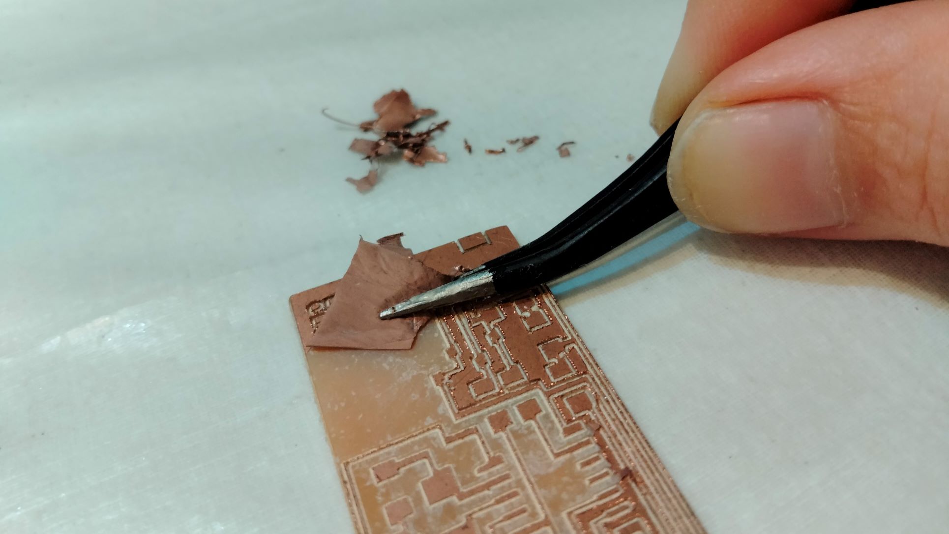
Before I could get to the exciting task of soldering, unfortunately I had to manually peel some of the copper to reveal a cleaner PCB and avoid making undesirable shorts while soldering. With the help of a paper knife and a tweezer, my PCB was transformed into a much more elegant version of former itself.


Firstly, I made 2 holes to position the USB mini socket, before tinting all the pads.
The first item to be soldered is the USB mini B socket, followed by the Attiny44, 2 diodes, 100 ohm resistors and the rest can be done in any order .


The final result looks quite nice. With a multimeter, I checked all the critical connections and made sure there is no short between VCC and GND.
Let’s now make it usable by uploading a firmware.
Loading the firmware to HelloISP
Step 1. Install WinAVR
Firstly, I installed WinAVR software.
Having followed a FabAcademy tutorial on FabISP up to this point, I was confused when it mentioned checking system path variables but failed to explain what is a PATH variable and how to find it. As is often the case, a Google search came to my rescue.
This site provides an explanation
- The PATH is the system variable that your operating system uses to locate needed executables from the command line or Terminal window.
- The PATH system variable can be set using System Utility in control panel on Windows, or in your shell’s startup file on Linux and Solaris.
- Making changes to the system PATH variable is typically not necessary for computers running Windows or Mac OS X.
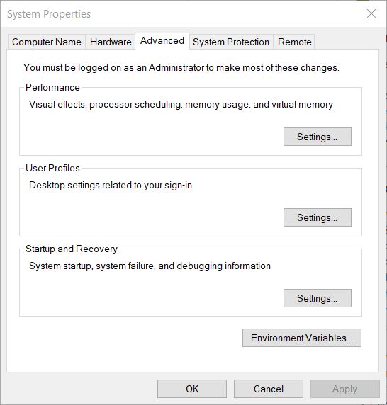
In Windows search bar, I typed “Advanced System Settings”. This opened up a System Properties dialogue. I then clicked Environment Variables.
Now in the Environment Variables dialog, the Path showed up. I clicked on Edit. and copy the
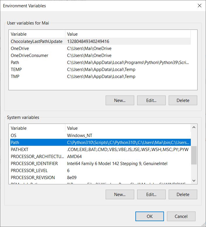
In the Edit Environment Variables dialog, under the section System Variables, I found the PATH environment variable, clicked on it, and then clicked Edit.
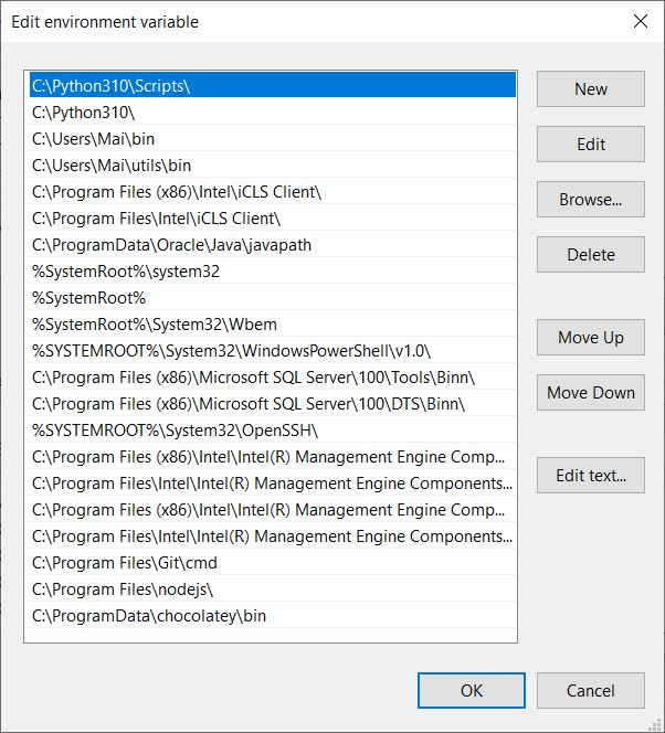
I clicked on the first line and ‘Edit text’.
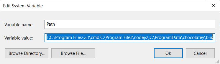
This allowed me to copy the following information
C:\Python310\Scripts\;C:\Python310\;C:\Users\Mai\bin;C:\Users\Mai\utils\bin;C:\Program Files (x86)\Intel\iCLS Client\;C:\Program Files\Intel\iCLS Client\;C:\ProgramData\Oracle\Java\javapath;%SystemRoot%\system32;%SystemRoot%;%SystemRoot%\System32\Wbem;%SYSTEMROOT%\System32\WindowsPowerShell\v1.0\;C:\Program Files (x86)\Microsoft SQL Server\100\Tools\Binn\;C:\Program Files (x86)\Microsoft SQL Server\100\DTS\Binn\;%SYSTEMROOT%\System32\OpenSSH\;C:\Program Files (x86)\Intel\Intel(R) Management Engine Components\DAL;C:\Program Files\Intel\Intel(R) Management Engine Components\DAL;C:\Program Files (x86)\Intel\Intel(R) Management Engine Components\IPT;C:\Program Files\Intel\Intel(R) Management Engine Components\IPT;C:\Program Files\Git\cmd;C:\Program Files\nodejs\;C:\ProgramData\chocolatey\bin;
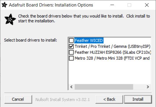
Step 2. Install a driver for AVR programmer
The driver is available from here. I downloaded and ran adafruit_drivers_2.5.0.0.exe. When prompted to select board drivers to install, I chose ‘USBtinyISP’.
Step 3. Download FabISP firmware
The firmware is available from here.
Step 4. Plug in HelloISP, install driver
doubled clicked on the first line and copied C:\Users\Mai\AppData\Local\Programs\Python\Python39\Scripts.
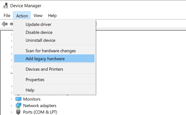
Upon plugging in, according to FabAcademy tutorial, I should be able to locate “FabISP” under “Other Devices” in Device Manager. However, ‘Other devices’ was nowhere to be seen, so I googled “other devices not showing in device manager windows 10”. Thankfully this video came to my rescue.
In Device Manager, select Action > Add a legacy hardware
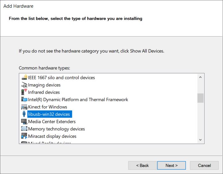
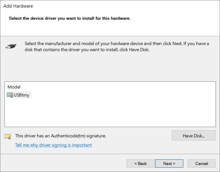
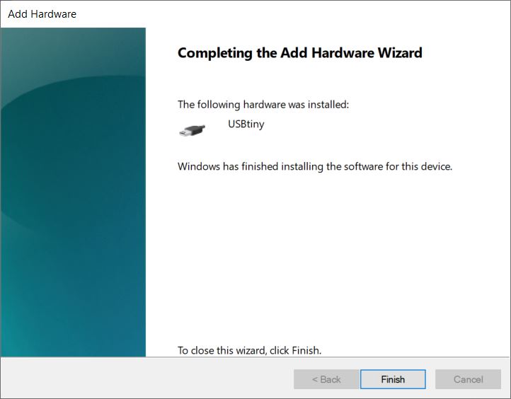 Click Finish.
Now lisubs shows up in Device Manager.
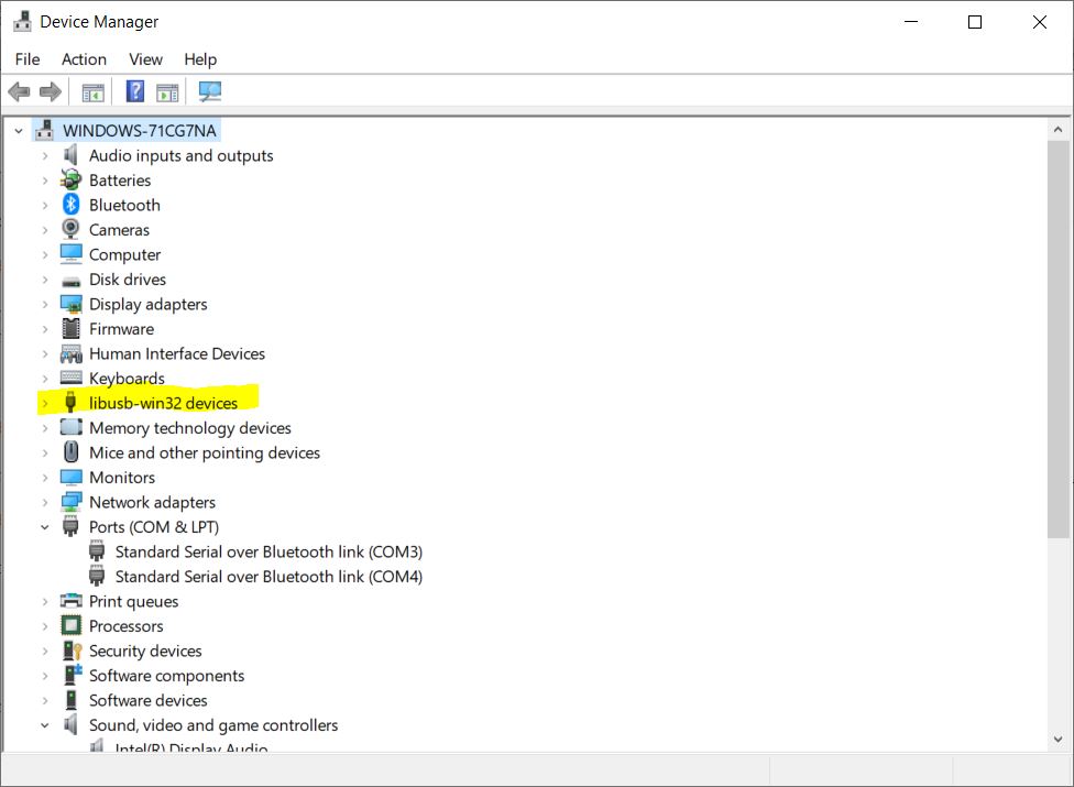
Right click on USBtiny and select Update driver.

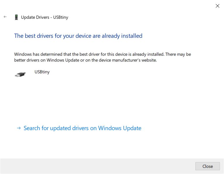
Step 5. Install the firmware
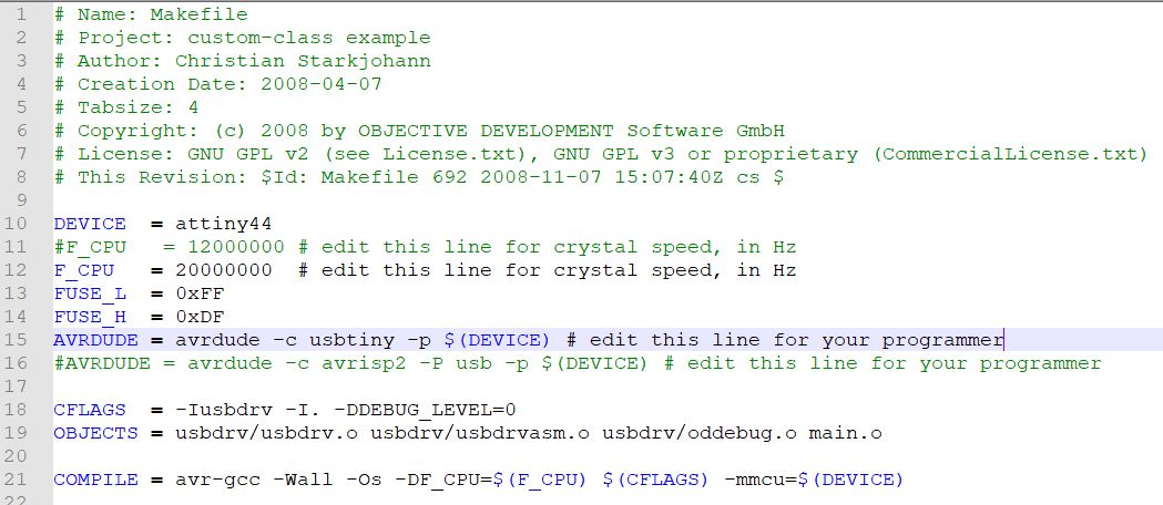
Using Notepad++, I opened the Makefile, removed the # from the line with usbtiny and put the # in front of the line below it.
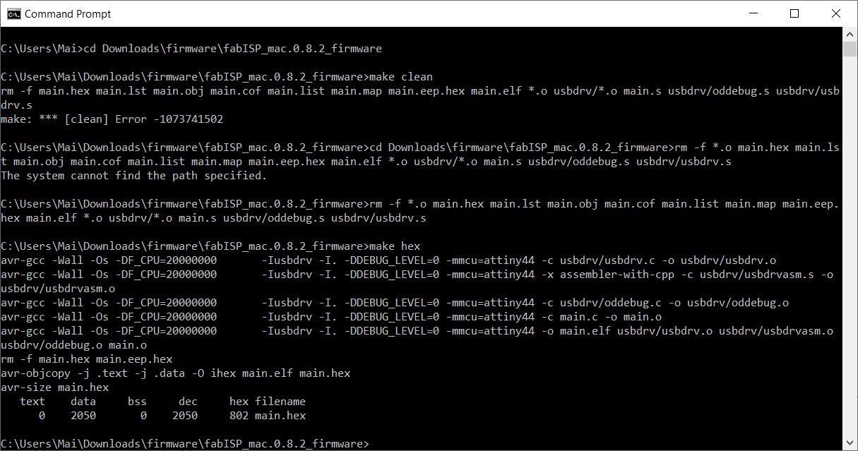
Running ‘make clean’ in Terminal window, I encountered the following error

The application was unable to start correctly (0xc0000142). Realizing that rm -rf .o may be a problem, I changed it to rm -f .o
rm -f .o main.hex main.lst main.obj main.cof main.list main.map main.eep.hex main.elf .o usbdrv/*.o main.s usbdrv/oddebug.s usbdrv/usbdrv.s
Next, I ran Terminal commands ‘make hex’ and ‘make fuse’. The former went well, but the latter returned an error.
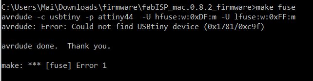
This tutorial mentioned the same make fuse error. The cause of this was none other than the fact that I had forgotten to connect my helloisp board to a programmer cable.
In my case, I had bought a USBasp programming cable which comes with a 10-pin connector, while the ISP programming header only has 6 pins. As a result, I connected the relevant pins from the USBasp to the onboard ISP connector.
Once done, ‘make fuse’ command ran succesfully, followed by ‘make program’.
With the firmware finally loaded to helloisp, I de-soldered the two 0 ohm resistors.
FabISPkey by Andy Bardagjy
I also attempted to mill FabISPkey by Andy Bardagjy. Too bad time was not on my side, and finishing the PCB was as far as I got.


Key learnings
To sum up my learning experience from this week, I have to say it is challenging to use V-bits to make PCBs. One must be very careful to ensure an even work area, and an appropriate depth of cut. Our machine was not rigid enough to make fine traces. I could not finish making the PCB in one week, and had to do the rest later than everyone else. On the other hand, I am happy to have tried using V-bits for this exercise and make my first foray into the PCB-making business.
Useful links
- Atmega16U2-based PCB design
- Daniel Meyer’s Fabacademy site
- Jacopo Dimatteo’s Fabacademy site
- Making a height map of PCB
- FabAcademy Tutorial for FabISP
- Guide: Programming a new FabISP Programmer
- Download WinAVR