9. Embedded programming
This week I learnt about various microcontroller families and how to program my board.
Group assignment
- Compare the performance and development workflows for different microcontroller families
Individual assignment
- Read the datasheet for the microcontroller you are programming.
- Program the board you have made to do something, with as many different programming languages and programming environments as possible.
Hero shot of the week
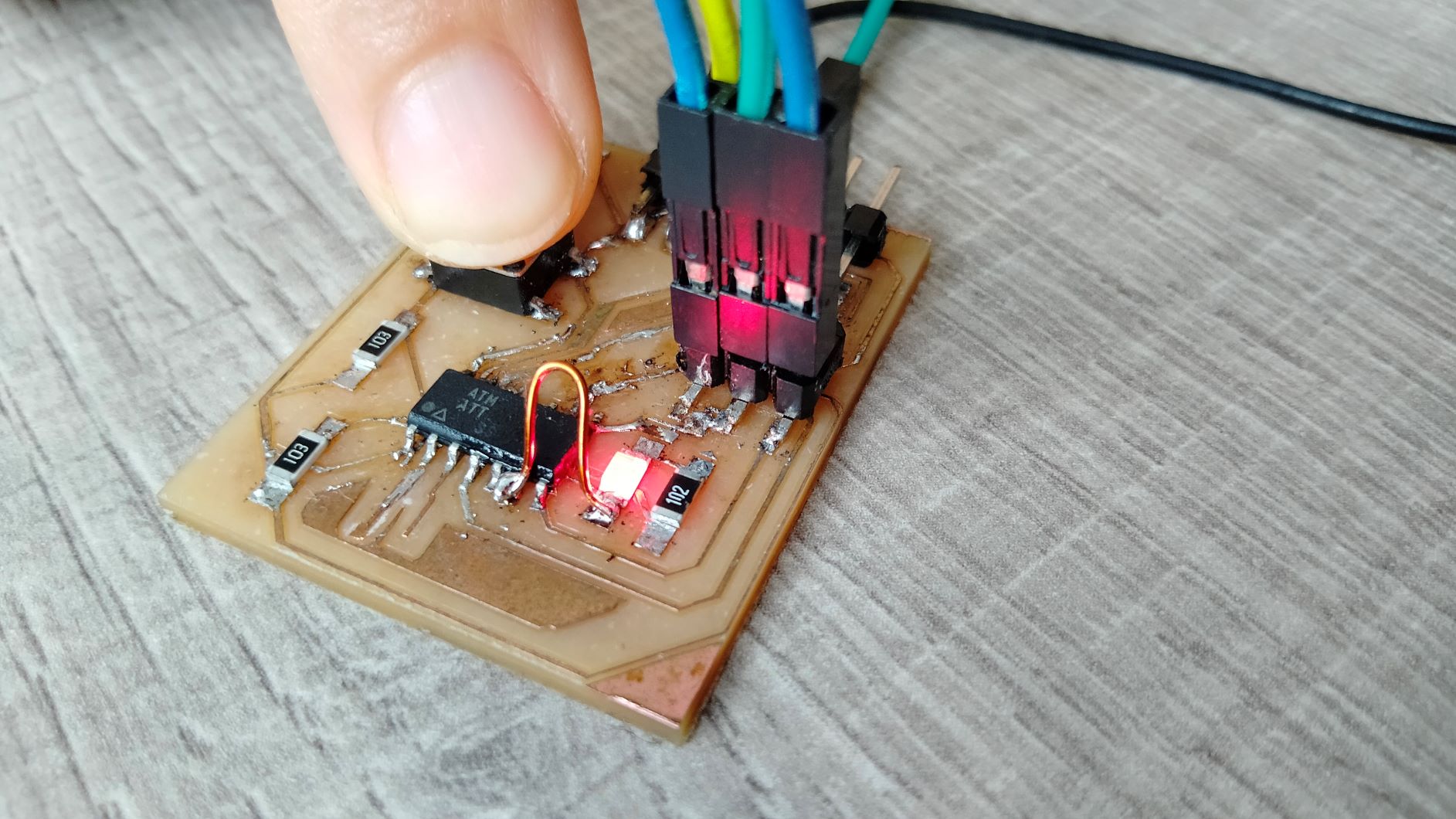 I programmed the LED to switch on whenever the button is pressed
Group assignment
Arduino Uno R3
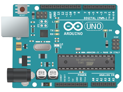 Image credit: prinsta.io
This is a very popular development board that is often recommended for newbies to electronics. It is developed by a group of Italian developers. Its key features are
- Microprocessor: ATmega328
- Flash Memory: 32 KB of which 0.5 KB used by bootloader
- SRAM: 2 KB (ATmega328)
- EEPROM: 1 KB (ATmega328)
- Clock Speed: 16 MHz
- Operating Voltage: 5V
- Input Voltage (recommended): 7-12V
- Input Voltage (limits): 6-20V
- Digital I/O Pins: 14 (of which 6 provide PWM output)
- Analog Input Pins: 6
- DC Current per I/O Pin: 40 mA
- DC Current for 3.3V Pin: 50 mA
Development workflow
As a general workflow, you will need to
- install Arduino IDE which is a programming environment
- connect the board to a USB port on your computer
- in Arduino IDE, open a new sketch
- go to Tools menu > Board > Board Manager > Arduino AVR Boards and select Arduino Uno
- also in Tools menu > Port > select the COM port to which your device is plugged in
- start programming in C
- compile your sketch by clicking on the tick icon above your sketch area
- upload the sketch by clicking on the right arrow icon, next to tick icon.
- press the Reset button to run the program. Note that sometimes the sketch will work right away without a need to press Reset.
Micro:bit (original version)
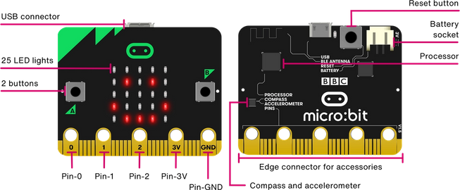 Image credit: microbit.org
This board was developed for K-12 students, which explains why its workflow is much simplified compared to Arduino. Its key features are
- Microprocessor: 32-bit ARM® Cortex™ M0
- Flash Memory: 256 KB
- RAM: 16 KB
- Clock Speed: 16 MHz
- Bluetooth Low Energy
- Two programmable buttons
- 3-axis digital accelerometer on-board
- 5x5 LED matrix for displaying text and animated pattern. This is an outstanding feature which makes it attractive to young learners.
- Operating Voltage: 3.3V
- Input Voltage (recommended): 4.5-12V
- Digital I/O Pins: 3 (of which 3 provide PWM output)
- Analog Input Pins: 3
- DC Current per I/O Pin: 700 mA
Development workflow
To get started, all you need to do is to
- plug it in to a USB port. It will appear as an external USB device
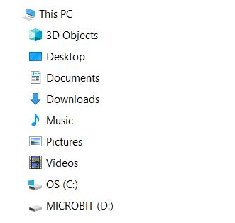
- program it immediately via web interfaces such as MakeCode, or a Python web editor.
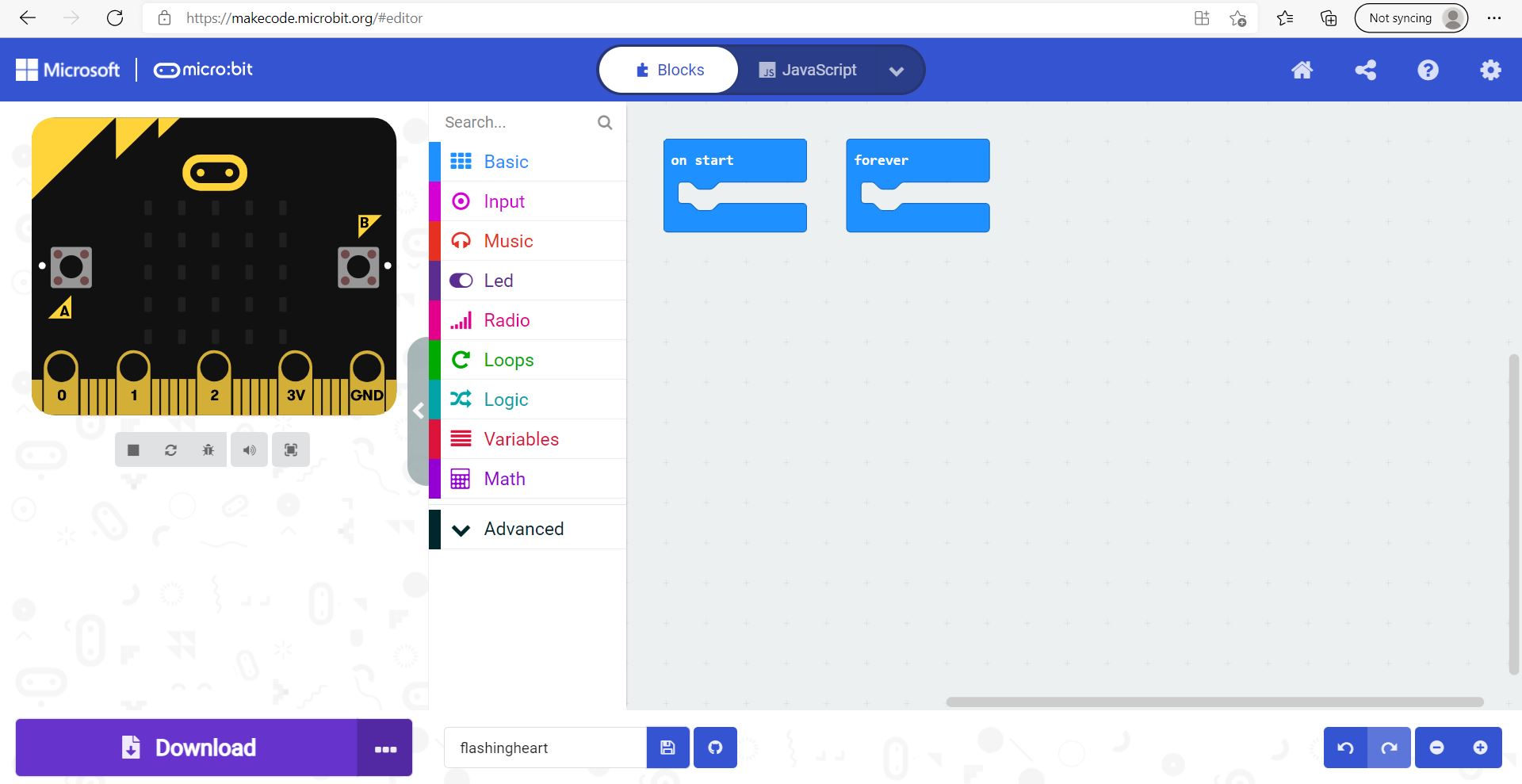
If you are using MakeCode editor, - Click New Project - drag and drop the blocks on the left-hand side to the right-hand window to start programming
The MakeCode interface is very well designed and friendly for beginners.
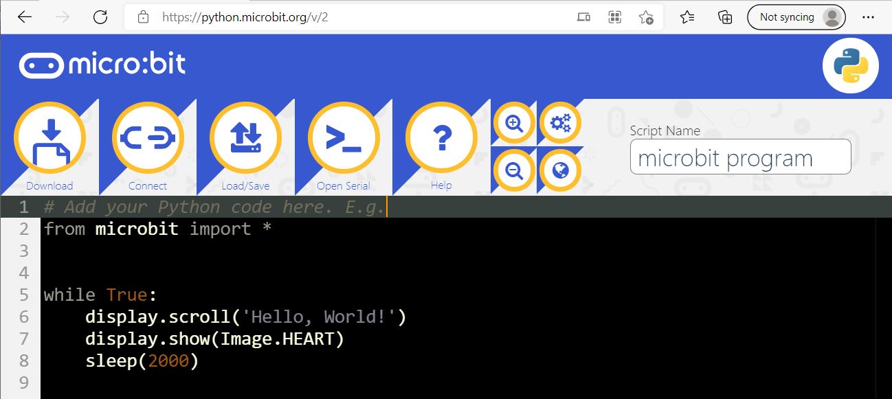
If you are using Python editor, - click Connect and select your board
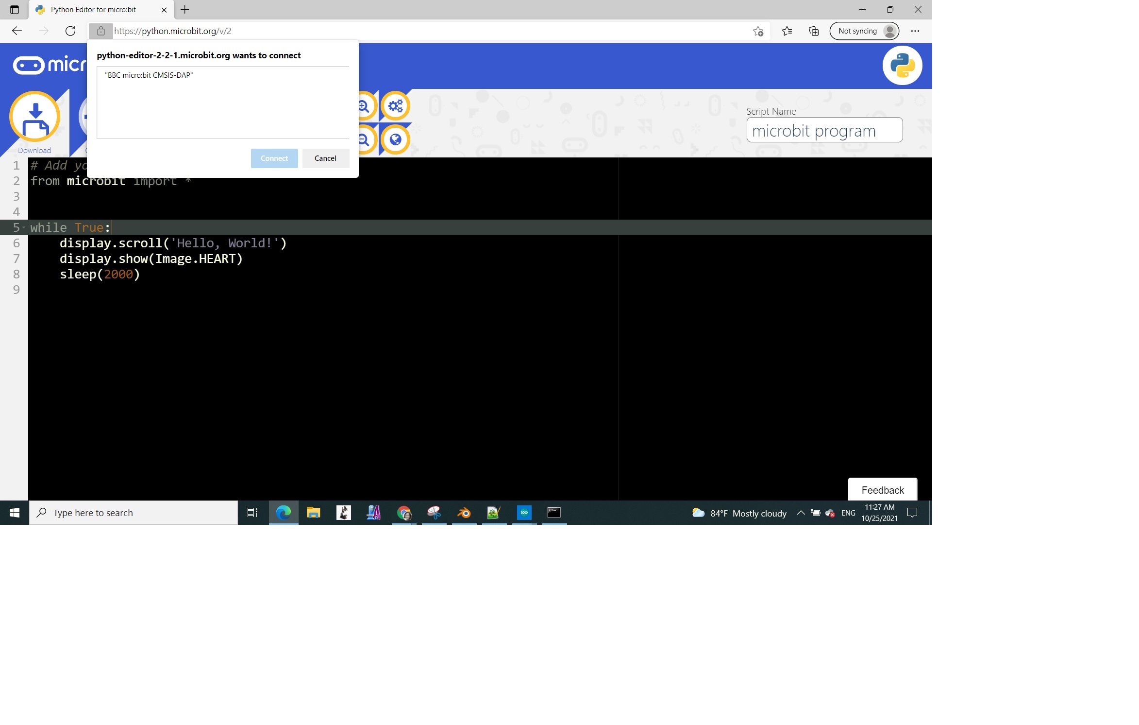

- write your Python script in the window
- click Flash to run your program

Both MakeCode and Python editors do not require initial technical configurations, unlike Arduino IDE, and are much more intuitive and easy to use compared to the latter.
Individual assignment
This week is challenging because of deadlines in my work and most importantly, I am still struggling with milling boards with proper traces.
Reading the datasheet
I went to the manufacturer’s website to look for the Attiny44 datasheet.
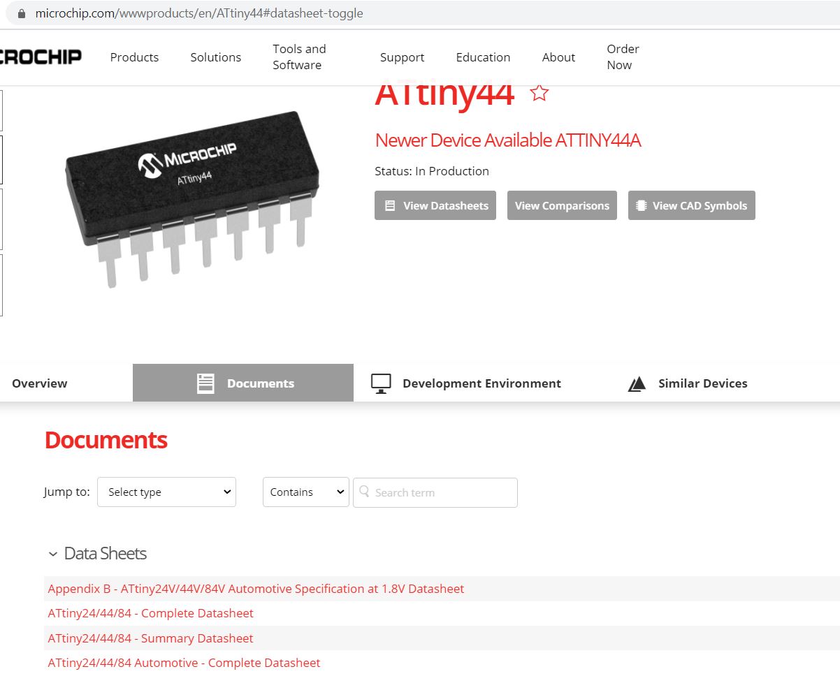
It’s interesting to note that there is an automotive edition for these chips. I did not know that. The automotive edition’s datasheet tells me that the main difference is in the operating temperature range. For automotive applications, the upper temperature requirement goes up to 125 degrees Celsius whereas for industrial applications, it is only 85 degrees.
Quickly glancing through the first page, we learn that
- it is an 8-bit microcontroller with RISC architecture.
- In terms of peripherals, it has one 8-Bit and one 16-Bit Timer/Counter with 2 PWM Channels and 10-bit ADC.
- it has 12 programmable I/Os
- it also has an internal calibrated oscillator and interestingly, an on-chip temperature sensor
- operates on 2 types of voltages (2.7V - 5.5V in my case)
The microcontroller has 2 I/O ports, Port A having 8 bits and Port B only 4 bits, each bit corresponding to a physical pin. This makes up 12 programmable I/Os. A diagram on page 2 of the datasheet describes the location of each pin. Further details about what each I/O pin can do are explained in “I/O Ports” section on on page 54.
Of particular interest for future applications, the PWM channels are on Port A bit 5 and 6.
Programming the board
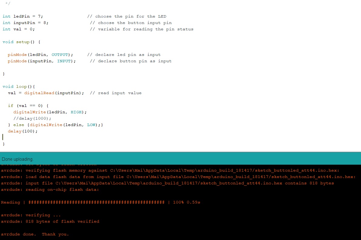
Working with the Hello board that I made for Electronic Design week, I programmed the LED to switch on whenever the button is pressed.

Same as previously, I uploaded the sketch in Arduino IDE by selecting Arduino as ISP.
I would like to try other ways to program the board, but for now, time is running short.