15. Networking and communications
This week I learnt about many wired and wireless communication protocols, and made my first ESP-32 board which I will use to check out ESP-NOW protocol for the first time.
Individual assignment
- design, build, and connect wired or wireless node(s) with network or bus addresses
Group assignment
- send a message between two projects
Research and planning
Given that I will want to use ESP-32 for my final project, my plan is to familiarize myself with an ESP chip this week.
For this exercise, I considered making a hello-ESP-01 board, and a hello-ESP32-WROOM. I went with the latter, the idea being to make the ESP32 communicate with my laptop as a client.

I am also interested to make two ESP32s to talk to one another via ESP-NOW protocol. If there is time left, I would like to learn about I2C communication.
Group assignment
The idea is to send a serial message between an Arduino Uno and my tinyMai board originally made for Embedded programming assignment.
If there is extra time, I might explore I2C protocol.

What I programmed: When a button on tinyMai is pressed, the onboard LED lights up (imagine a trepassing is detected, and a security light switches on). Not only that, TinyMai also sends the character 1 to the Arduino (the teacher) to alert the latter it that a trepressing has taken place. The Arduino sends back character 2 as an knowledgement and blinks its own LED to indicate an emergency.
Here is a demo.
Code for Arduino (master)
#include <SoftwareSerial.h>
SoftwareSerial mySerial(0,1); //RX,TX

char msgout = '2';
char msgin;

void setup() {
  mySerial.begin(9600);
  pinMode(LED_BUILTIN, OUTPUT);  // declare led pin as input

}

void loop(){
  msgin = mySerial.read();  // read input value
  mySerial.print(msgin);

  if (msgin == '1') {
    //mySerial.print(msgin);
    mySerial.write(msgout);
    digitalWrite(LED_BUILTIN, HIGH);
    delay(100);
    digitalWrite(LED_BUILTIN, LOW);
  };

  delay(100);

}
Code for ATtiny44 (student)
/*
 * Light up LED when a button is pressed, and send an alarm message to the Master
 */
#include <SoftwareSerial.h>
SoftwareSerial mySerial(1,0); //RX,TX

char msgout = '1'; //'Intruder';
char msgin;

int ledPin = 7;                // choose the pin for the LED
int inputPin = 8;               // choose the button input pin
int val = 0;                    // variable for reading the pin status

void setup() {
  mySerial.begin(9600);
  pinMode(ledPin, OUTPUT);     // declare led pin as input
  pinMode(inputPin, INPUT);     // declare button pin as input
}

void loop(){
  val = digitalRead(inputPin);  // read input value

  if (val == 0) {
    digitalWrite(ledPin, HIGH);
    mySerial.write(msgout);
    //delay(1000);
  } else {digitalWrite(ledPin, LOW);}

  msgin = mySerial.read();
  mySerial.print(msgin);
  delay(100);

}
Individual assignment
Making Hello ESP-32 WROOM boards
Before designing my own PCB for ESP-32, I wanted to test with Neil’s design.


I milled the traces with a 20-degree 0.1mm-tipped v-bit and outline with a 0.8mm corn-teeth endmill.
My MODS setting for v-bit milling:


Preparing the components

Let the soldering start. I secured the ESP32 on the pads quite quickly after putting a bit of solder on the underside but it was really tough to solder the pins without shorting them with the GND connection.
 .
.
I tried to remove excess solder with a wick but that did not help. Both TX and RX on the ESP are shorted with GND. Somehow the solder kept spilling out.
At this point, I thought of re-designing the PCB to add more space for easy soldering. Fortunately, I came across Barduino.
I did try milling the ESP-32 WROOM two more times to get thicker traces, before moving on to Barduino.

Powering up ESP32-WROOM
Connecting the VCC and GND of ESP32-WROOM board to a 3.3V regulated power source, as well as the RX and TX to an FTDI board which was plugged to a computer, I was able to power up the ESP32-WROOM just to confirm that it is alive.

As soon as the ESP-32 was powered up, it sends a bunch of text to the serial monitor on the computer.

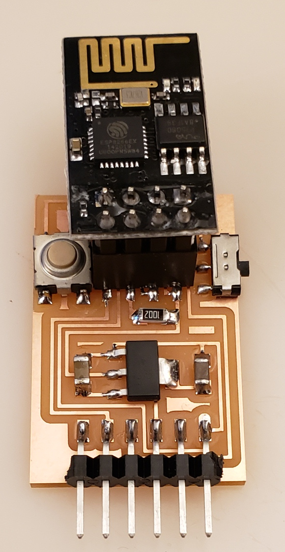
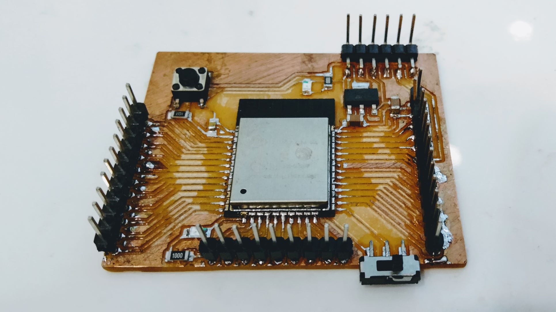
Barduino
Barduino is an ESP-32 break-out board developed exactly for the reason I mentioned earlier, by Eduardo Chamorro Martin with the help of Josep Marti and Oscar Gonzalez in Fab Lab Barcelona 2020. There are 2 versions of this board ; the most recent one - version 2.2 is below on the left and version 2.0 on the right. For those curious, version 1.0 already existed as an arduino atmega based alternative developed by Luciano.


I was hoping to mill this before the weekly meeting, but due to shortage of time, I did this afterwards.
Soldering Barduino
Uploading a sketch
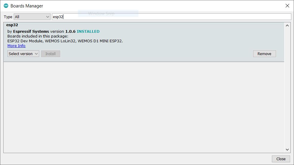
First I typed in ESP32 in a Board Manager. As indicated, the package is already installed on my IDE, since I had used ESP32 device for an earlier assignment. If you have never done this before, press Install.
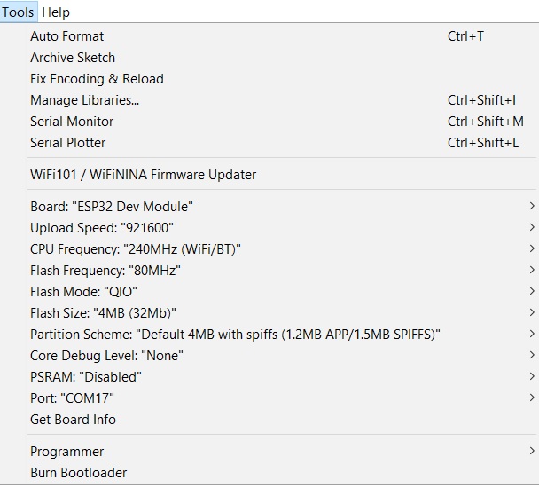
When selecting Programmer, I was surprised to find “No programmers available for this board”. Having googled to see why this is the case, I found an answer on Stackexchange. Here is a screenshot of the settings that I used to upload hello.ESP32-WROOM.echo sketch provided by Neil.


I made sure that mode switch on the Barduino is set to PROG (programming) mode, before pressing Upload.


If you forget to set the right mode, you will get the error message “A fatal error occurred: Failed to connect to ESP32: Timed out waiting for packet header “. Fret not, simply switch to PROG and you should be able to upload again.
Subsequently, I opened the Serial monitor, switched back to RUN mode, pressed the Reset button and the following message appeared.

Fortunately, the ESP32-WROOM echo sketch can finally be uploaded without any glitch. This is the serial print-out.

Blinking an LED
The next basic step in testing any new board is to blink an on-board LED. I loaded an example sketch for that, and the only modification needed was changing the built-in LED to be 13.
 .
.
Failed to connect to Esp32: Invalid head of packet (0x6F)

Apparently this is because every time the device is unplugged, Windows reverted back to the old routine. I would have to re-specify the driver to be the older version. Once this is done, uploading a sketch to Barduino is possible again. With the program uploaded, I switched the board back to RUN mode and the LED started blinking right away!
Setting up the ESP32 as a Wifi client

Interfacing with Blynk app
Blynk is a mobile app that allows you to connect to your wifi devices from your phone.
Having installed the app, there are 2 additional steps we need to make. First, we want to upload a sketch to our ESP32 board to tell which Wifi to connect to. Second, we will configure the Blynk app to connect to LED pin 13.
Step 1. Connecting ESP32 to WiFi
A long time ago, I had Blynk installed for an IoT project, so when I typed in Blynk in the Arduino libraries search field, it says Installed.

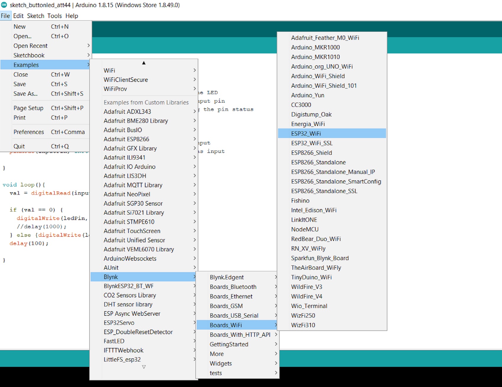
Next I called up an example sketch ESP32_WiFi from the Blynk library and replaced the three parameters “YourAuthToken”, “YourNetworkName” and “YourPassword” with the actual details.
Note that the first parameter will be emailed to you when you create your first project in Blynk app.


Step 2. Configuring Blynk app
In creating a new project in Blynk app, I selected ESP32 Dev board and WiFi. Subsequently, I added a button and connected it to pin 13 so that I toggle the LED.
Then I pressed the triangle icon at the top right corner in order to sync with the ESP32. All went smoothly. Now every time I pressed the button in the app, the LED lit up momentarily.
ESP-NOW
ESP-NOW is a fast communication protocol developed by Espressif that enabled small messages (up to 250 bytes) to be exchanged between ESP32 boards even when there is no Wifi. According to Espressif, the protocol is similar to the low-power 2.4GHz wireless connectivity often seen in wireless mouses. Pairing between devices is needed prior to their communication. Once paired, the connection is secure and peer-to-peer, with no handshake being required.
What is great here is that it is low-power and allows for one-way or two-way communication via MAC Address. The protocol supports up to 20 connected devices.
My initial idea was having the ESP32-WROOM control an ESP32-CAM development board. Since my self-made board did not work in time, to test ESP-NOW protocol, I used two ESP-CAM boards which I happened to order a few weeks ago for Machine Design week.

Code Example
The following code examples come from a tutorial by Rui Santos.
Get a MAC Address for your ESP32
#include "WiFi.h"

void setup(){
  Serial.begin(115200);
  WiFi.mode(WIFI_MODE_STA);
  Serial.println(WiFi.macAddress());
}

void loop(){

}
After flashing the above code in Arduino IDE to one of the ESP32-CAM boards, I opened the Serial Monitor and set a baud rate of 115200. Upon my pressing the ESP32 RST/EN button, the MAC address was printed on the screen:

You can see that its MAC address is 24:0A:C4:EF:16:0C. However, on the second ESP32-CAM board, I received a funky message before seeing a MAC address at the very end, 3C:61:05:3C:04:F4.

After a while, I tried flashing the same code again to the second board. Oddly, this time, the serial monitor received properly displayed characters, the MAC address staying the same. I wish I knew what changed.

ESP32 Sender Sketch
/*
  Rui Santos
  Complete project details at https://RandomNerdTutorials.com/esp-now-esp32-arduino-ide/

  Permission is hereby granted, free of charge, to any person obtaining a copy
  of this software and associated documentation files.

  The above copyright notice and this permission notice shall be included in all
  copies or substantial portions of the Software.
*/

#include <esp_now.h>
#include <WiFi.h>

// REPLACE WITH YOUR RECEIVER MAC Address
uint8_t broadcastAddress[] = {0xFF, 0xFF, 0xFF, 0xFF, 0xFF, 0xFF};

// Structure example to send data
// Must match the receiver structure
typedef struct struct_message {
  char a[32];
  int b;
  float c;
  String d;
  bool e;
} struct_message;

// Create a struct_message called myData
struct_message myData;

// callback when data is sent
void OnDataSent(const uint8_t *mac_addr, esp_now_send_status_t status) {
  Serial.print("\r\nLast Packet Send Status:\t");
  Serial.println(status == ESP_NOW_SEND_SUCCESS ? "Delivery Success" : "Delivery Fail");
}

void setup() {
  // Init Serial Monitor
  Serial.begin(115200);

  // Set device as a Wi-Fi Station
  WiFi.mode(WIFI_STA);

  // Init ESP-NOW
  if (esp_now_init() != ESP_OK) {
    Serial.println("Error initializing ESP-NOW");
    return;
  }

  // Once ESPNow is successfully Init, we will register for Send CB to
  // get the status of Trasnmitted packet
  esp_now_register_send_cb(OnDataSent);

  // Register peer
  esp_now_peer_info_t peerInfo;
  memcpy(peerInfo.peer_addr, broadcastAddress, 6);
  peerInfo.channel = 0;
  peerInfo.encrypt = false;

  // Add peer
  if (esp_now_add_peer(&peerInfo) != ESP_OK){
    Serial.println("Failed to add peer");
    return;
  }
}

void loop() {
  // Set values to send
  strcpy(myData.a, "THIS IS A CHAR");
  myData.b = random(1,20);
  myData.c = 1.2;
  myData.d = "Hello";
  myData.e = false;

  // Send message via ESP-NOW
  esp_err_t result = esp_now_send(broadcastAddress, (uint8_t *) &myData, sizeof(myData));

  if (result == ESP_OK) {
    Serial.println("Sent with success");
  }
  else {
    Serial.println("Error sending the data");
  }
  delay(2000);
}
In order to reflect the 3C:61:05:3C:04:F4 MAC address of the receiver, I modified the following line of code
uint8_t broadcastAddress[] = {0xFF, 0xFF, 0xFF, 0xFF, 0xFF, 0xFF};
to
uint8_t broadcastAddress[] = {0x3C, 0x61, 0x05, 0x3C, 0x04, 0xF4};
Having flashed the above code to the sender board, I started the Serial monitor which shows Delivery fail. This is not surprising, since the receiver board has not been programmed yet.

ESP32 Receiver Sketch
#include <esp_now.h>
#include <WiFi.h>

// Structure example to receive data
// Must match the sender structure
typedef struct struct_message {
    char a[32];
    int b;
    float c;
    String d;
    bool e;
} struct_message;

// Create a struct_message called myData
struct_message myData;

// callback function that will be executed when data is received
void OnDataRecv(const uint8_t * mac, const uint8_t *incomingData, int len) {
  memcpy(&myData, incomingData, sizeof(myData));
  Serial.print("Bytes received: ");
  Serial.println(len);
  Serial.print("Char: ");
  Serial.println(myData.a);
  Serial.print("Int: ");
  Serial.println(myData.b);
  Serial.print("Float: ");
  Serial.println(myData.c);
  Serial.print("String: ");
  Serial.println(myData.d);
  Serial.print("Bool: ");
  Serial.println(myData.e);
  Serial.println();
}

void setup() {
  // Initialize Serial Monitor
  Serial.begin(115200);

  // Set device as a Wi-Fi Station
  WiFi.mode(WIFI_STA);

  // Init ESP-NOW
  if (esp_now_init() != ESP_OK) {
    Serial.println("Error initializing ESP-NOW");
    return;
  }

  // Once ESPNow is successfully Init, we will register for recv CB to
  // get recv packer info
  esp_now_register_recv_cb(OnDataRecv);
}

void loop() {

}
The above code was flashed successfully to the second board.
Testing ESP-NOW Communication (one-way)
Now that both the sender and receiver boards have been programmed and plugged into the USB ports of my laptop, I started the serial monitor for the sender board.

On the receiver’s end, we received THIS IS A CHAR and other information.

As you can see, this one-way communication worked between these two ESPs. What would be interesting to do next is establish two-way communication between them.
Useful links
- Menghe Xu’s ESP32 project for Fabacademy
- Toshiki Tsuchiyama’s ESP32 project for Fabacademy
- Barduino’s GitHub
- ESP-NOW Tutorial by Rui Santos
- ESP-NOW Two-way Communication Tutorial by Rui Santos