11. Input devices
This week’s assignment we need to design a board that uses an input device. It can be any device able to measure something, and should have a microcontroller to manage it. I have decided to design a distance sensor. This sensor might be used in the final project, to identify the distance of the robotic arm and the object to catch. So this weeks assignment might be helpful for the final project.
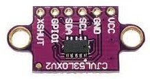
For this assignment I am gona make use of the sensor VL53LXX. Specifically, we have in our lab the sensor VL53L0X. This is an easy sensor that can be added in the circuit. It communicate with the microcontroller via I2C represented by the pins SDA and SCL.. Mostly microcontrollers offer the I2C communication.
PCB Design - first try
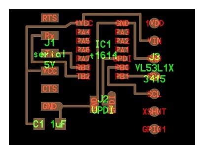
There is available one PCB example in the FabAcademy schedule that makes use the VL53L1X sensor. The difference of this sensor to the version we have in the lab is the order of the pins SDA and SCL. I decided to try to use this board example because it would save some time and I could program the ATtiny via UPDI. Until now I have used the ISP to program the ATtiny in previous assignments and I would like to try a different strategy this time.
Milling board
To mill the board, I have used the lines also found in the FabAcademy web site. I have done the following steps to mill it.
-
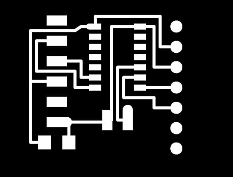
I have imported this image in Inkscape. Executed the function bitmap trace (menu: Path > Trace Bitmap) and saved the resulted image as DXF file.
-
Imported the file in a PCB design cloud software EasyEDA. One collegue has experience in this software and I give a change to try it. Apparently it provides a good amount of footprint of components that can be added in the board. However, importing the DXF file did not work because the image imported had only the external lines and I need the lines filled to mill the board. Conclusion: first two steps was waste of time.
-
We imported then the image directly to EasyEDA. I change the real scale of the image because the imported image was too big. The correct scale I used was height of 17.5 and width 19.25. I have to try several scales until we got the correct one.
-
I have generate the gerber files (ZIP file) with the image in the correct scale. Gerber file is used to generate the traces for the milling machines 3020 CNC Engraving Machine.
-
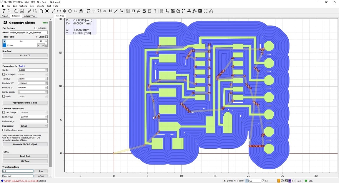
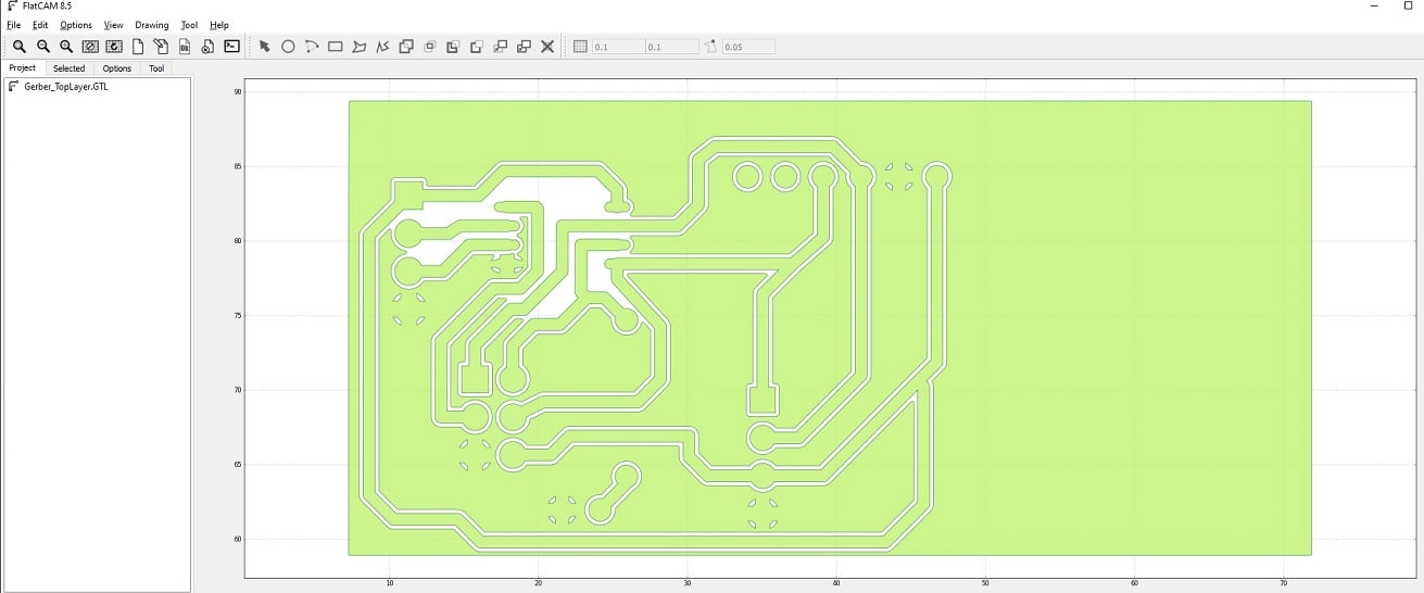
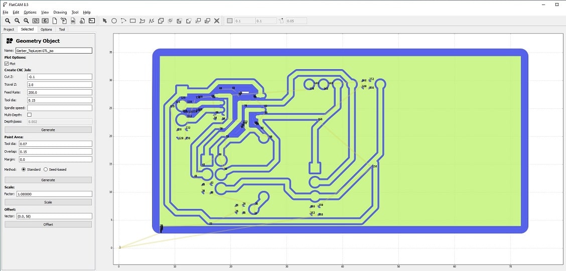
Then I installed FlatCAM that is able to edit and prepare the file for the milling machine.
- From the zip file, I have imported only the top layer, that contains the lines of the circuit to mill the board.
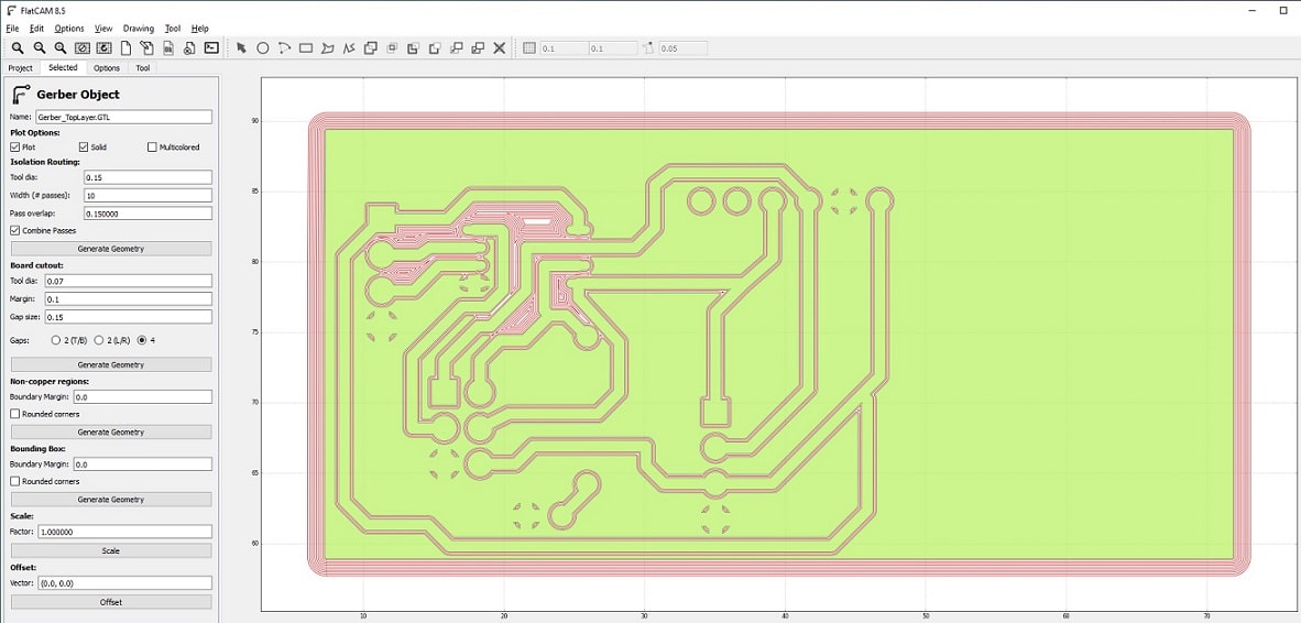
- I have tried different isolation routing because this define the width of the lines of the board. The correct value used was 0.4mm. I added 10 passes in total. Used the function to generate the Isolation Geometry of the image.
- Then adjusting the parameters Feedrate X-Y and Z to respectivelly 120 and 60 from the geometry object created in the previous step. Then I used the function Generate CNCJob object that will be send to the mill machine.
- Saved as CNC code to be loaded in the machine.
-
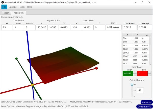
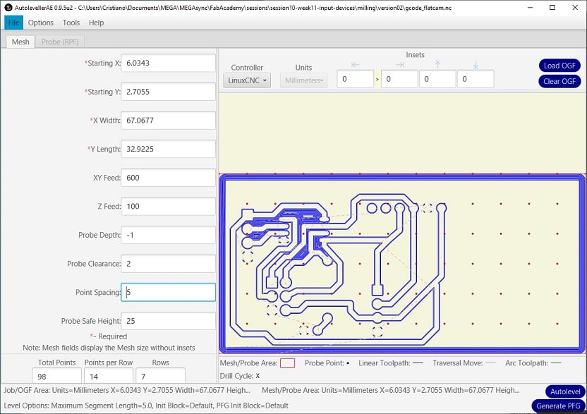
I installed AutolevellerAE that is used to adjust the probing of the machine to guarantee the PCB is correctly milled.
- Import the generated CNC file in it
- Set the probing matrix (Point Spacing) 5mm between each point. This is the number of points the machine will check to calculate the probing.
- Use function Generate PFG, it saves a CNC file with the points to check the probing.
- Do not close the software.
-
The CNC file created in the AutolevellerAE will be used to adjust the probing of the machine in the CNCJob that will mill the PCB. For this, I made use of the Mech3 software to adjust the probing of the machine, guaranteeing the PCB will be correctly milled.
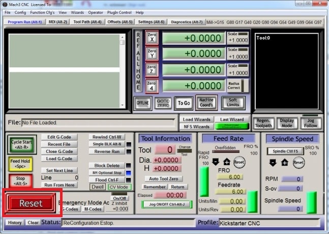
- Make sure the reset button on the black box is not pushed in.
- Click in the reset button in the software (it should not be blinking anymore)
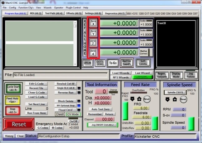
- Import the CNC file (menu: File > open)
- Move the position the needle to the beginning of your board and position as close as possible of the board. Adjust the zero axis’ of the software clicking in the respective buttons.
- Using the key Tab you can swicth the view of the software for the select job mode that enables you to more the needle by milimeters.
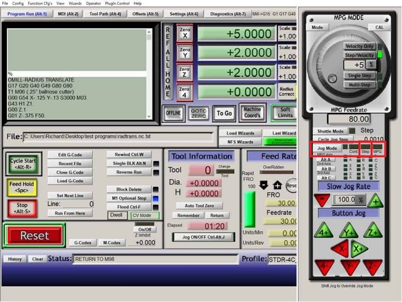
- After the setup is done, hit the button Cycle Start. The machine will start to calculate the probing file for adjusting the CNC file.
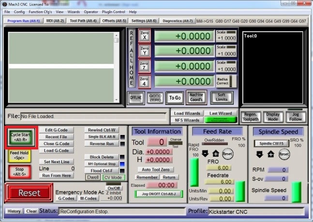
- Save the probing file as TXT.
-
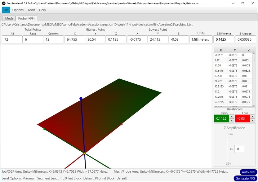
Back to AutolevellerAE, adjust the probing of the machine to guarantee the PCB is correctly milled.
- Import the probing coordenates (menu: File > Raw probing file).
- This will adjust the original CNC file (generated by FlatCAM) with the probing coordenates from the machine.
- Executed the function Autolevel to generate CNC file considering the probing coordenates of the machine.
Soldering components
I have used the following components:
- ATtiny1614
- Sensor VL530X
- Pin headers for Serial and UPDI connection
- Capacitor of 1µF
Programming via UPDI
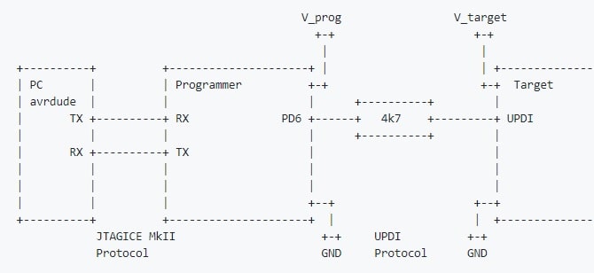
I have searched for tutorials on how to program via UPDI and I liked the explanation given by the youtube channel bitluni Programming the new ATtiny from Arduino using UPDI [Beginner Tutorial]. Its explanation was very simple and straightforward. Here are the steps to take to program the ATtiny via UPDI.
-
Upload the jtag2updi code in the arduino for making it work as UPDI programmer.
-
Disable the reset option from the arduino by adding a capacitor between the reset pin and the GND (positive leg of capacitor in the RST pin). This is important to avoid the arduino reseting the board every time we try to upload the code.
-
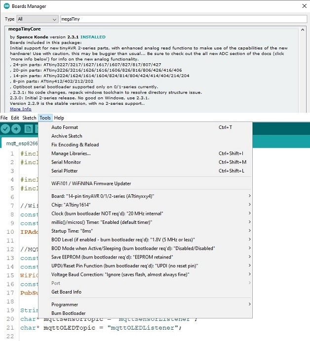
Install megaTinyCore in the ArduinoIDE, using the Additional Boards Manager URL http://drazzy.com/package_drazzy.com_index.json (menu: File > Preferences > Settings > Additional Boards Manager URLs). I have installed the most recent version of megaTinyCore (2.3.1) and this version provides slight different options than previous one showed in the tutorial.
-
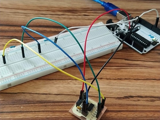
Connect a resistence 4k7 in between the connection of the pin D6 from Arduino and the UDPI pin from ATtiny1614 (pin 11, also the RST). I used a breadboard to hold the resistence and the connections between Arduino and UPDI.
-
Connect the ATtiny1614 in the GND and the VCC.
-
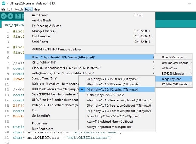
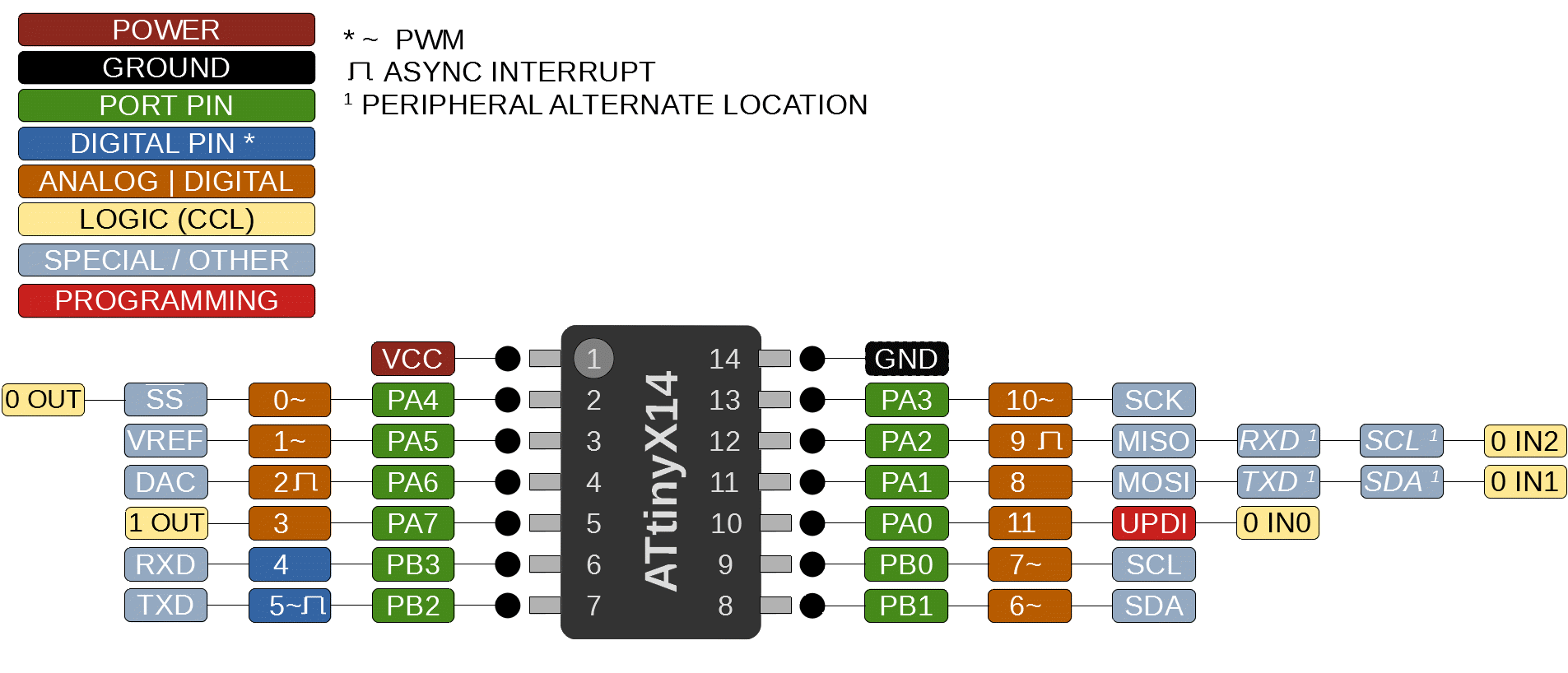
Select the correct board in the ArduinoIDE megaTinyCore 14-pin tinyAVR 0/1/2-series (ATtinyxxx4) (menu: Tools > Board > megaTinyCore). Make sure to select the correct USB port. The clock from ATtiny can be adjusted according to your interest, lower clock requires less power. I followed the tutorial, and used 20Mhz.
-
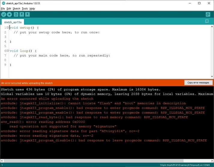
I upload an empty sketch, and it worked as explained in the tutorial. ArduinoIDE returned the error “avrdude: jtagmkII_initialize(): Cannot locate “flash” and “boot” memories in description”, but it seems a common error and it does not mean the code were not flashed in the microcontroller.
-
Then, I connected a LED in the pin 7 from the ATtiny1614 (including another resistence 4k7 to avoid the LED to burn).
-
I uploaded the following sketch (simple blink):
int PIN_PB0_7 = 7; void setup() { pinMode(PIN_PB0_7, OUTPUT); } void loop() { digitalWrite(PIN_PB0_7, LOW); delay(1000); digitalWrite(PIN_PB0_7, HIGH); delay(1000); } -
Initially I have connected the LED in the wrong pin, I should connect the GND in the resistence that goes to the ATtiny and the other leg in the VCC. I connect both in the GND. Changing the connection, the LED blink as expected.
I have learned in these steps how to program an ATtiny via UPDI. Notice that not all microcontrollers offers the possibility to program via UPDI.
Check the pinout of the board to see if it is possible to use, before taking any action.
Programming sensor
Then I attached the sensor in the board and tried to load the code for reading the sensor measurement.
-
Upload library VL53L1X-arduino in the ArduinoIDE (library offered in the FabAcademy website). This library manage the distance sensor and provides a function to get the measurement.
-
Upload Continuos example from the library, but it did not work. After uploading this sketch example, the ATtiny stoped to work. I made a huge mistake in this step, because I changed the clock from ATtiny to a lower value (1MHz internal) and I immediatelly tried to load the code.
-
I spend some time investigating what would be the problem and how to fix it. Used a command that interprets possible problems during the step that flashes the sketch into the ATtiny. I could not see the reason or how to fix it after reading a couple of forums.
<arduino_directory_path>\packages\arduino\tools\avrdude\6.3.0-arduino18/bin/avrdude -C <arduino_directory_path>\packages\megaTinyCore\hardware\megaavr\2.3.1/avrdude.conf -c jtag2updi -P COM4 -p t1614 -v -v -v -v -
Talking with an expertise in hardware, I got to know that after changing the clock used to flash the ATtiny, I should use the function Burn Bootloader (menu: Tools). I was using clock 20MHz and changed to 1MHz to save energy, but I did not use this function before flashing the code. As consequence, I started to get the error code RSP_ILLEGAL_MCU_STATE when I tried to flash any code into the ATtiny. I learned that the ATtiny is in a state that cannot be flashed. Hence, after changing any value in the configuration of the microcontroller, before flashing the code I need to use the function Burn Bootloader (menu: Tools).
To fix this error, it would be necessary to reset the ATtiny. Unfortunately, it was not possible because I did not expose the needed pins from the microcontroller to enable connecting it to a programmer to reset it. This was also another mistake I made in this first try of designing the PCB for the assignment. Because of this, I decided to restart the assignment, but now testing the circuit before milling the board (that should be the correct strategy to take when designing eletronics application).
PCB Design - second try
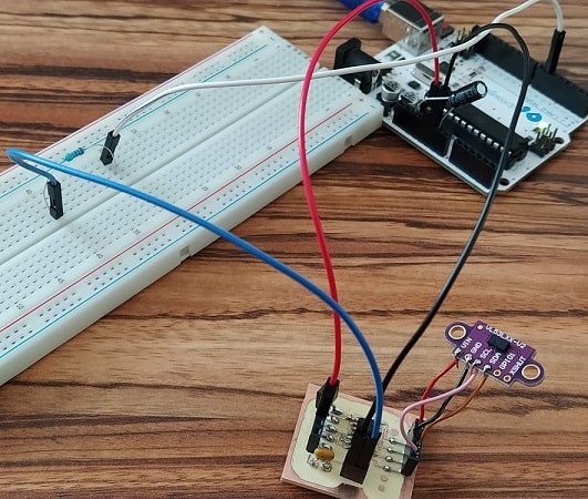
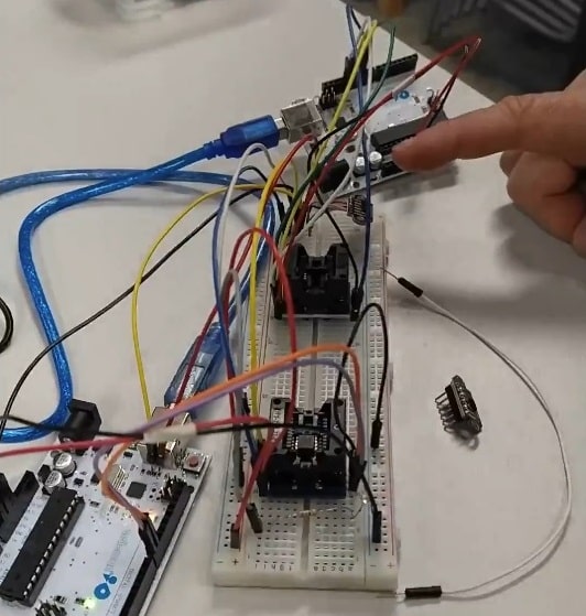
This time, before milling the board, I decided to design a prototype of the circuit to be sure it would work as I expected. I have used two arduinos and two sockets for ATtiny85. As we did not have sockets for ATtiny1614 in our lab, I changed the microcontroller to ATtiny85. In one set of components I used to program the ATtiny85 using ISP (that was used sucessfully previously). In the other set, it was the real circuit that I want to implement.
Prototype
The circuit is very simple, the sensor attached to the microcontroller, and a led with resistence to have an alternative to make sure the circuit works. The second arduino works only to provide VCC and GND to the circuit. But also a possibility to setup a serial connection with the microcontroller.

- Flash ArduinoISP example in one ArduinoUno to program ATtiny.
- Connected ArduinoUno via ISP to the ATtiny85
- Flash an empty sketch in the ATtiny85 - OK
- Connected a LED in the PB1 (it is a pin not used by the sensor) pin from ATtiny85.
- Flash a blink sketch in the ATtiny85, the LED blinked correctly - OK
- Based in the example code of the sensor VL53L0X, I edited the sketch to turn the LED on when the sensor is lower than 10mm, otherwise turn off the LED.
- Flash this edited sketch in the ATtiny85 - OK
- After connecting the sensor in the correct ports of the ATtiny85, the sensor was not able to detect the distance and turn on the LED. The library was not compatible to the sensor I was using (VL531X).
- Install library Adafruit_VL53L0X, however it was too big and could not be flash in the ATtiny85 due to memory constraint.
- Install library VL53L0X that is compatible to the version of the sensor used and it can be flashed in the ATtiny85.
- The microcontroller could read the distance measurement from the sensor.
Drawing
-
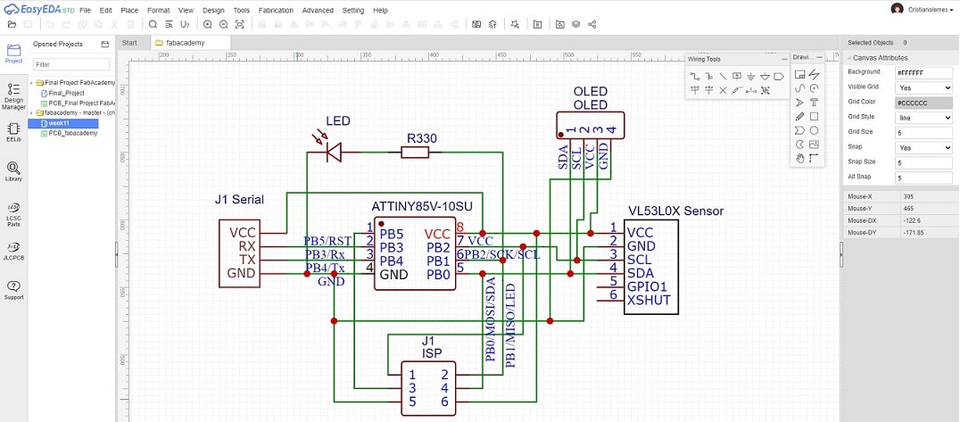
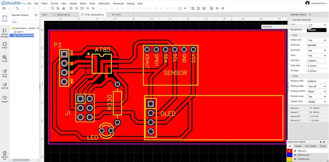
I have drawn the circuit using EasyEDA adding the necessary components and their connections.
-
I have also included an OLED that will be used in the assignment for Output Devices. Here are the lines of the circuit.
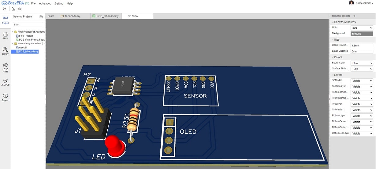
-
Here a 3D visual of the PCB.
Download the ZIP file generated by EasyEDA containing gerber file for milling the designed PCB.
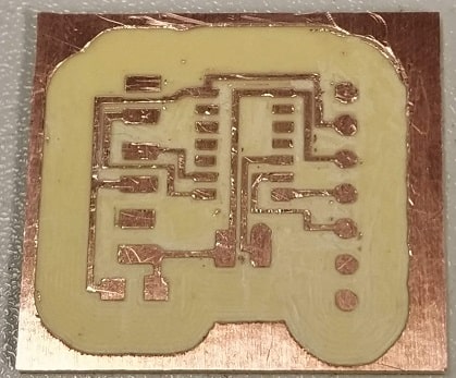
Milling board
I have followed the same steps explained before to mill the board.
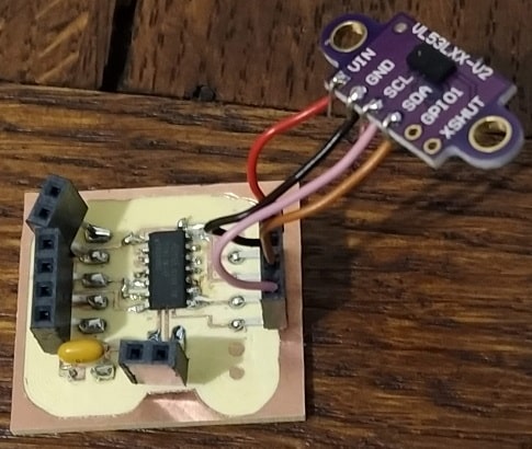
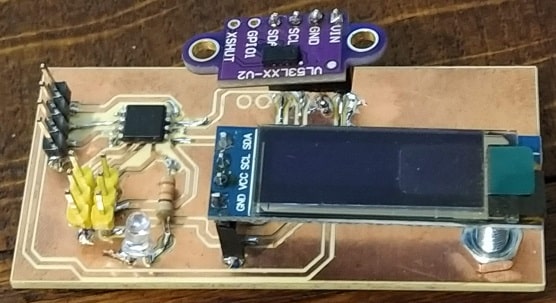
Soldering
I have used the following components:
- ATtiny85
- Sensor VL53L0X
- two sets of pin headers, (i) for serial connection and (ii) for ISP connection.
- one LED and one resistor 330ohm.
- OLED that will be used in the next assignment (Output devices).
I used one screw only to support the OLED.
Programming
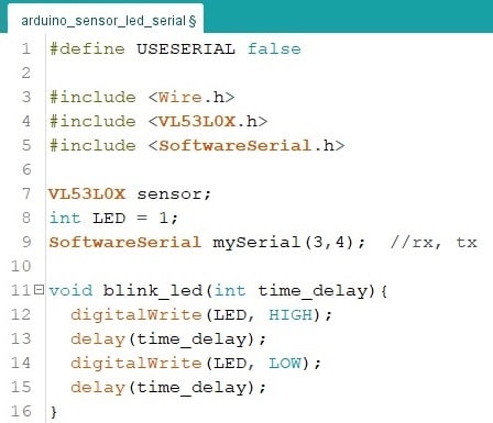
I also used a customized serial port. Two output pins (PB3 and PB4, respectively 3 and 4) from the microcontroller I setup to work as serial sending messages.
-
Declaration of variables, inclusion of libraries for the microcontroller, and an auxiliar function definition to blink the led.
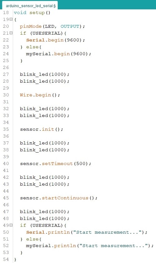
-
Setup function from microcontroller.
- set pin LED as OUTPUT.
- initialize Wire (for SDA and SCL communication between microcontroller and sensor).
- initialize parameters from sensor.
- added some blinks to check which phase of setup is running.
-
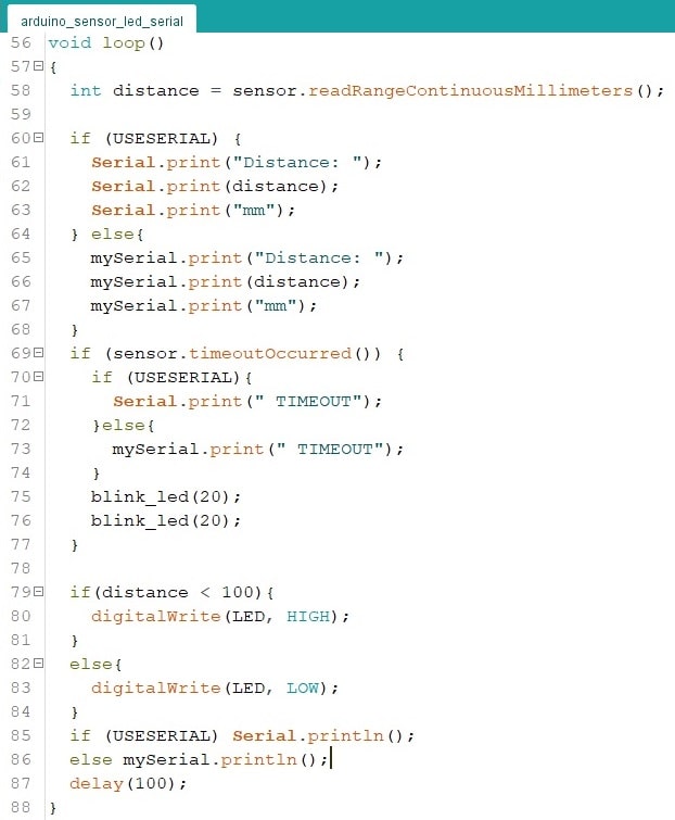
Loop function from microcontroller.
- Read distance measurement from sensor.
- Print it in the serial output.
- Validate if the sensor still works, blinking the led case not.
- if the distance is less than 10mm, turn on the LED.
Download the INO file from the microcontroller code