5. Electronics production
The task of the week is to design and build a programmer practicing electronics production and soldering. The assignment is divided into three parts: (i) mill a board, (ii) soldering the components, and (iii) write the code of the programmer.
Milling machine
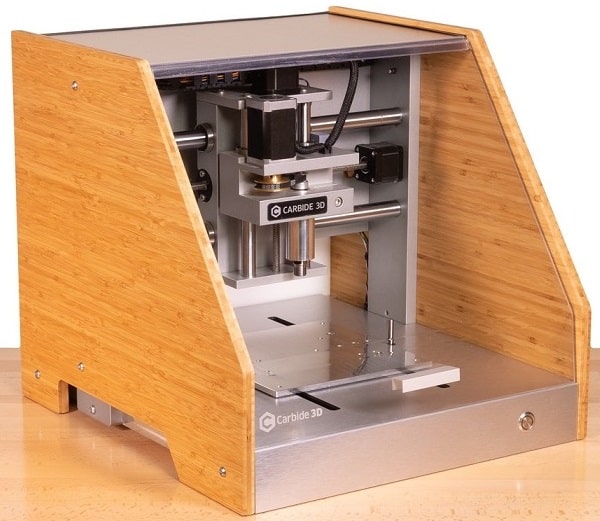
The circuit’s drawing of the board we need to produce is given. We just need to convert into vectorial image to use in the milling machine. We decided to use the machine Carbide 3D Nomad machine in this assignment. This is a multi purpose milling machine that has a very user friendly interface. The disadivantage of this machine is that is not possible to make lots of changes in the paths of the circuit to mill. This is the price for having a generic machine compared to the ones dedicated to milling PCBs.
Testing machine
Before we started, we check out some tutorials on how to operate the machine. The video Nomad 883 CNC Machine: PCB Milling gave a good start point to start testing the machine. Then we used double-sided tape in the board, place it in the machine and move foward to test it.
Even though, it was a challenge to test the machine. We tried different tools and settings and the quality of the board was not good. The machine was also not leveled because the lines was good in some places, and in others not much.
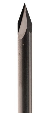
The machine came with a standard tool, called PCB Engraver 502, that has .005” Ball tip (.0025” radius) and 40 Degree Tip Angle. However, this tool was not able to make small cuts which was necessary to mill the lines of the PCB we need to design.
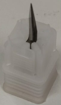
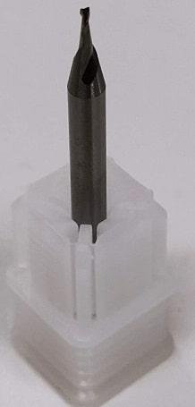
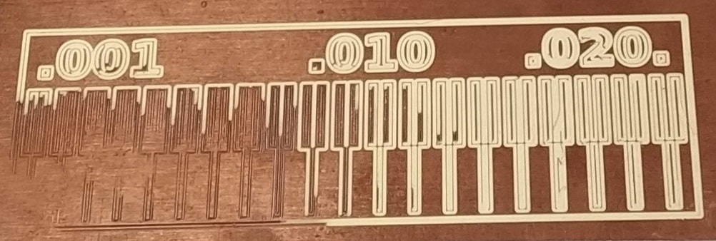
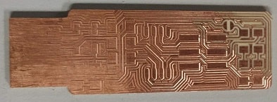
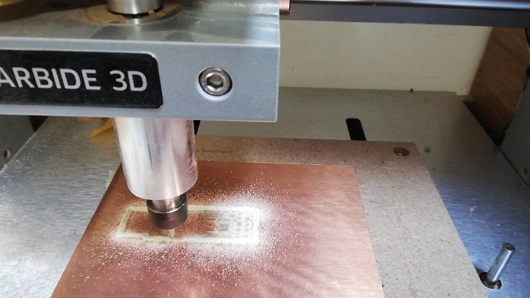
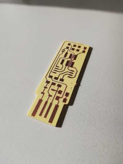
Then we tested the milling process using two different needles: (i) X and (ii) 0.032”. Then a default image was milled in the board to check the precision of the machine (iii). It was noticed the mat of the machine need to be adjusted and it was noticed the side bottom-left provided a better precision in the milling process. We also noticed the tape was too flexible and we pushed one side harder than the other. We change for a better tape, and the result was better. The needle 0.032” was good for cutting the PCB, but not to mill the lines of the circuit. Needle X produced the best results for thin lines (iv). For large areas, it took some time, but it worked well.
| (i) Needle X | (ii) Needle 0.032” |
|---|---|
 |
 |
(iii) Testing milling machine
(iv) PCB engraver with needle X
Preparing circuit lines
We can use two types of micro processor in this board: (i) attiny 45 or (ii) attiny 85. At ingegno we have available the attiny 85, so following is show the drawings of the circui of the board.
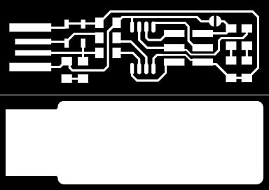
The image was converted to vectorial image using Inkscape.
Preparing CNC file
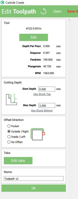
The Carbide 3D machine works with the Carbide Create software, that is the software designed specifically for this machine. We first imported the vectorial image in the software and made the toolpaths
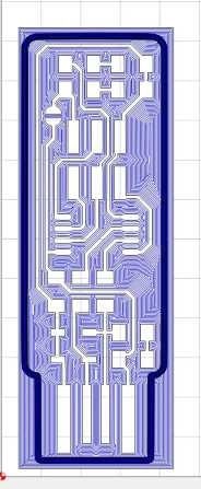
This was the setting for cutting out the board. This configuration worked well and it was able to cut around the board without damage the circuit lines.
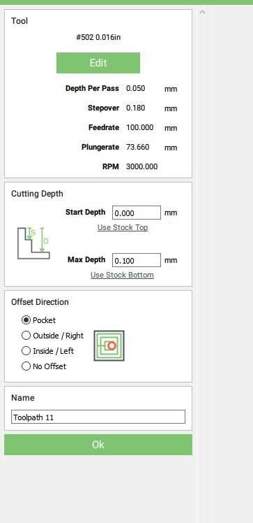
This was the settings used to engrave the board (to make the circuit lines).
It was attempted to create the smallest board possible, however the small scale does not provide good lines for the board, not considered to build the programmer.
After a lot of try and error, we could finally find the right setting. We have changed the depht per pass, the feedrate, and the stepover. After found a good scale, the board was milled.
We concluded that the bigges problem was to adjust the initial position of the Z-axis. We had to do it manually for each job, everytime a new board was loaded in the machine. But luckly, we could had a good result after all try and error.
Soldering the components
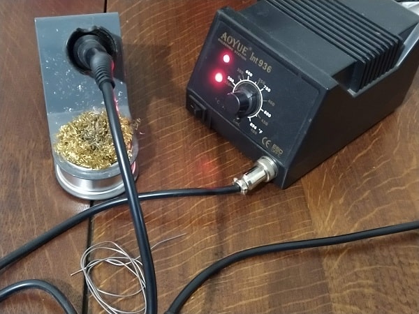
This was the machine used to solder the components. It is composed by the soldering iron and station, metallic sponge, and a support for the soldering iron. The soldering station is connected to the electricity and will power the soldering iron. Soldering iron is heated up to melt the tin and fix the components in the board. The metallic sponge is used to keep the soldering iron clean and away from oxidation. The support is used only to hold the soldering iron avoiding to burn the base of the workstation (work table). The soldering station was adjusted in 350°C for a medium heating up of the soldering iron.
List of components
List of components to solder in the board
- 1x Attiny85 (or Attiny45).
- 2x 1kΩ resistors.
- 2x 499Ω resistors.
- 2x 49Ω resistors.
- 2x 3.3v zener diodes.
- 1x red LED.
- 1x green LED.
- 1x 100nF capacitor.
- 1x 2x3 pin header.
Where to place them
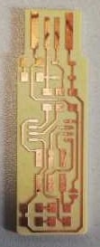
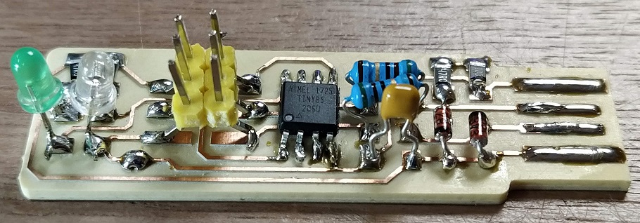
The image bellow shows where exactly to solder each component in the board.
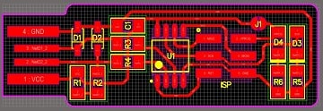
- R1 and R6 are the 1kΩ resistors.
- R2 and R5 are the 499Ω resistors.
- R3 and R4 are the 49Ω resistors.
- C1 is the capacitor.
- D1 and D2 are the 3.3v zener diode.
- D3 is the green LED.
- D4 is the red LED.
- the U1 is the attiny. when you’re going to solder it, you have to make sure of the orientation, there’s a little dot on the attiny, and it should go where this dot is.
- J1 is just a bit of tin to connect both sides. this will be undo after to program the board.
BE CAREFUL:
- The LEDs have to be placed in the correct polarity otherwise they will not work as expected.
- The attiny has the correct orientation to be placed in the board. In the component you will find a little dot and it should be placed in the bottom left as shown in the image above.
It was not easy to solder the components because it was not possible to hold the component, the tin and the soldering iron. Unfortunatelly, I did not have a magnifying glass with holder and tweezers. To make easier to solder the components, I added bit of tin in one of the side of the component on the board. Then I solder on side of the component (using the tin in the board) and then I could hold the tin and place the component in a way that will not break easily.
The dimension of the components were challenge as well. I had to use a clamp to help in the solder process.
Programming board
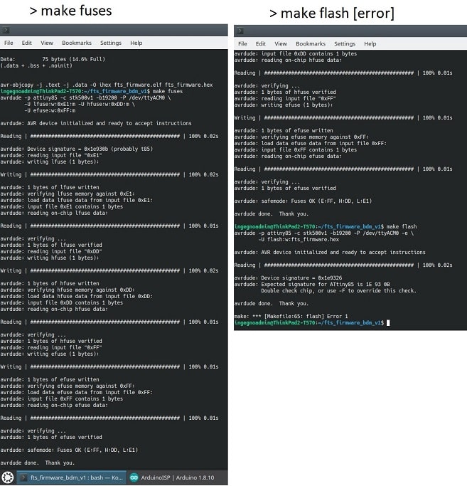
After finishing to sold the components, I have tried to program it using the tutorial (here). It was possible to compile the firmware from this website correctly, however the command make flash that start to communicate with the programmar, it failed because the tutorial did not provide all information necessary to program the board. It was missing the explanation about the USB address that was being used to connect the programmer to the computer.
Then we started to investigate another tutorial (here). It required to connect the programmer board on a Arduino containing an ISP code (native from the Arduino IDE). It was possible to compile the firmware and execute the first command make fuses successfully. When I tried to execute make flash (that actually send the code to the programmer), it failed due to wrong device signature. My guess is that when trying to send the code to the board, it was trying to send the code to the arduino instead of the programmer board.
After trying to understand the problem and finding a solution, we got support from a friend that explained how to configurate the Arduino to work as bridge between the computer and the programmer board. After using this configuration, we could configurate the board correctly. Following it is described the steps taken to program the board.
Preparation
I followed the tutorial described here using the OS Linux. I have installed the Arduino IDE and softwares make, avrdude, and avr-gcc (including its dependencies).
>sudo apt-get install make
>sudo apt-get install binutils gcc-avr avr-libc uisp avrdude flex byacc bison
Note: the command sudo is necessary to install programs on Linux, otherwise you will not have privilegies to install the software.
Setup Arduino
-
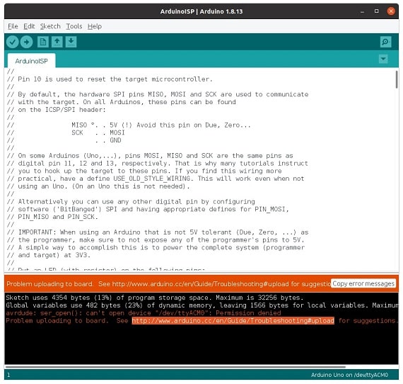
Upload the code example ArduinoISP (File > Examples > ArduinoISP). I have faced a permission error trying to access the path of the USB used to connect the Arduino in the computer.
-
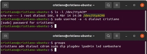
Investigating the error, it was necessary to add the user mode dialout in the groups of the OS (details).
- Could not upload because avrdude did not have permission to access the USB port.
- It was necessary to grant permission to the group “dialout”.
- checked if the group were added correctly “prompt > groups”
- ls -l /dev/ttyACM –command to check the name of the user mode of the USB port
- sudo usermod -a -G dialout cristiano –change ‘cristiano’ by your OS user name
- groups –check if the group were included correctly
-
If you had the same error in the step one and fixed in step 2, try to load again the code example from step 1 in the arduino. It should work now. Otherwise, continue the steps.
-
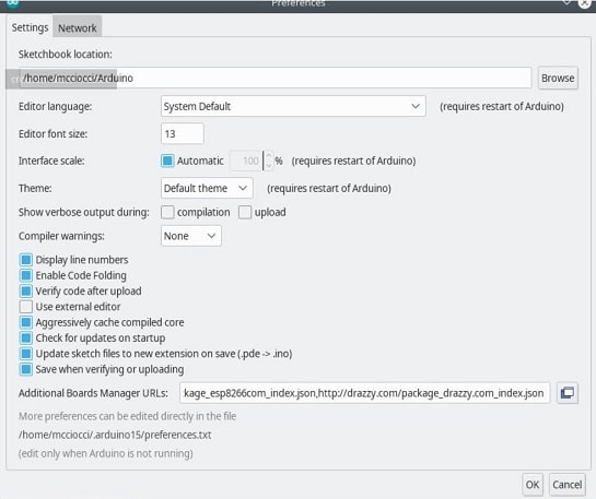
Install ATTinyCore library in the ArduinoIDE.
- Add the link http://drazzy.com/package_drazzy.com_index.json in the Additional Boards Manager URLs option from ArduinoIDE (menu: File > Preferences, Tab Settings).
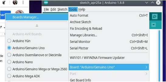
- Open the window Boards Manager (menu: Tools > Board: “Arduino/Genuino Uno” > Boards Manager)
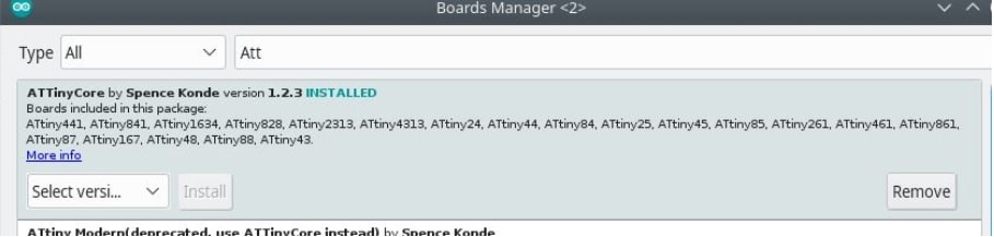
- Search for AttinyCore and install it.
- Add the link http://drazzy.com/package_drazzy.com_index.json in the Additional Boards Manager URLs option from ArduinoIDE (menu: File > Preferences, Tab Settings).
-
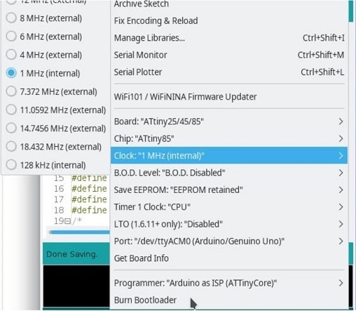
Select the correct configuration for Arduino works as a bridge to your board.
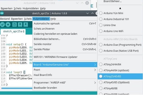
- Select the board you are using in your programmer ATtiny25/45/85 (because I used ATtiny85) (menu: Tools > Board: “Arduino/Genuino Uno” > ATtiny25/45/85.
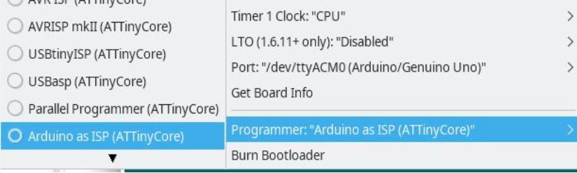
- Configure the programmer qs Arduino as ISP (ATtinyCore) that will stablish the arduino as bridge to your programmer (menu: Tools > Programmer > Arduino as ISP (ATtinyCore)).
- Use the following programmer properties values:
- board: ATtiny 25/45/85
- chip: ATtiny85 (or the chip you are using in your programmer)
- clock: 1MHz (internal)
- Other properties use the default value.
- Select the board you are using in your programmer ATtiny25/45/85 (because I used ATtiny85) (menu: Tools > Board: “Arduino/Genuino Uno” > ATtiny25/45/85.
-
You can proceed to setup the firmware of your programmer.
Firmware
I have seen several files of firmware for the programmer. Most of them are focused on the ATtiny45 and it is not compatible with the ATtiny85 that I am using. From the files I have seen I missed a very important information: the USB port address the arduino (or the programmer) are connected. The tutorial I am following provided a very good firmware, but for the ATtiny45 and you should change the file for the ATtiny 85 (if you are using this one). If you are using the ATtiny85 you can use the firmware I will post here, otherwise look for the correct firmware according to the type of attiny you are using. Following the steps taken to compile and load the programmer.
-
Download firmware for the ATtiny85. If you are using a different ATtiny, find the proper firmware for it. Make sure you know the USB port address your arduino is connected in your computer, otherwise the files will not be loaded in your programmer. For me, the port was /dev/ttyACM0.
-
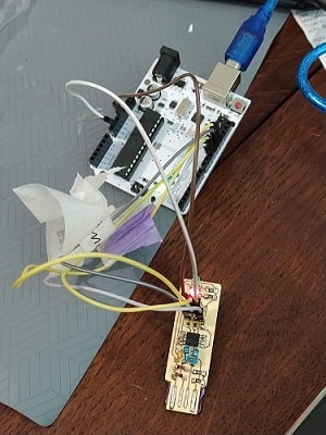
Connected the Arduino and the programmer according to the following image. Do not forget to connect the programmer with the voltage, that actually make the board work.
Arduino Programmer 13 SCK 12 MISO 11 MOSI 10 RST GND GND 5V V 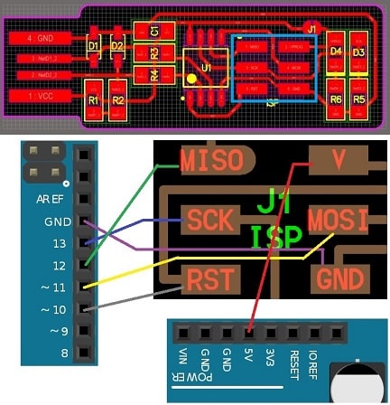
-
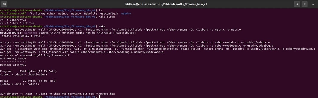
Make sure the makefile from firmware fits your OS and USB port where arduino is connected. Execute the following commands:
- make clean – to clean previous compiled files
- make – to compile the files via makefile
-
Execute the following command lines to create the .hex file and send it to the your programmer
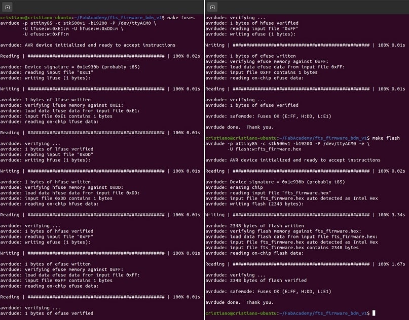
- make fuses –create the .hex file
- make flash –send it to the programmer
-
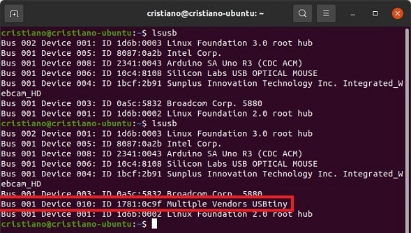
Disconnect the board from the arduino and connect in your computer. Executing the command in the prompt lsusb, you should see in the list “Multiple Vendors USBtiny”
-
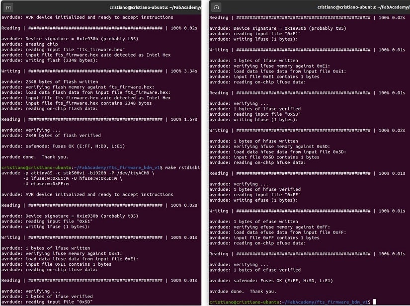
Reconnect the board in the arduino (step 2) and execute the command to set the reset disable bit in your board.
- make rstdisbl
- make rstdisbl
-
You can remove the connection to the jumper and the programmer is ready to be used.
Group Assignment
Ingegno - Electronics Production