Week 14: Interface and Application Programming
I was a little nervous starting this week, as I have no experience with mobile development, and am hesitant to go down a rabbit hole and get in way over my head.
May 5
I have heard of a number of the topics Neil discussed in lecture, but much of it went over my head. There are obviously many powerful tools that can be used to make professional mobile applications to interface with electronics, but I unfortunately don’t have have the time to learn these tools.
I shared a link to Espressif Rainmaker, which is a service offered by Espressif, the company that develops the ESP32 modules. It provides an SDK, cloud hosting, and drag-and-drop app templates to simplify the IoT development process. Unfortunately, the code needs to be compiled in Espressif’s ESP IDF for it to be compatible with Rainmaker. From what I can gather, migrating the code to this new platform would require some time and effort. While I don’t intend to do this during the course, Rainmaker could be an interesting option moving forward.
Another option discussed was MIT App Inventor. This is a web-based, coding-block-based service that allows the user to build drag-and-drop apps within the web platform, then send them to the mobile companion app by scanning a QR code. A big benefit of this platform is that there is a large user community that post tutorials, so there is a good chance that I could find some useful resources when I run into issues. Also, apps created on this platform can also interface with sketches in the Arduino IDE, which is a big positive considering the time limitations. While the example apps look pretty clunky, this seems like my best option to get something up and running within a week.
In lecture, I shared a link to my Week 13 documentation to demonstrate an IMU and OLED talking over I2C when a student who was presenting said that they were having difficulty with this process. They were using an ATTiny processor which has much less flash memory than the ESP, and Neil mentioned that the OLED library takes up a large amount of storage. Henk shared a link to this library which is considerably smaller. As the firmware for my device becomes more complicated, I may want to look into moving away from the Adafruit OLED and GFX libraries that I currently need to include for my sketch to run.
After class, I continued to build off the sketch I had created for Week 13, and I merged it with the sketch from Week 10 where the hall effect sensor triggered the RGB LED. The code is as follows:
#include <Adafruit_MPU6050.h>
#include <Adafruit_SSD1306.h>
#include <Adafruit_Sensor.h>

Adafruit_MPU6050 mpu;
Adafruit_SSD1306 display = Adafruit_SSD1306(128, 32, &Wire);

int hallEffectPin = 25;
const int ledPinGreen = 26;
const int ledPinBlue = 27;
int state = 0;
int motor = 14;

void setup() {

  pinMode(ledPinGreen, OUTPUT);
  pinMode(ledPinBlue, OUTPUT);
  pinMode(hallEffectPin, INPUT_PULLUP);
  pinMode(motor, OUTPUT);

  Serial.begin(115200);
  // while (!Serial);
  Serial.println("Indispensable Pill Case - MPU6050 & OLED Test");

  if (!mpu.begin()) {
    Serial.println("Sensor init failed");
    while (1)
      yield();
  }
  Serial.println("Found a MPU-6050 sensor");

  // SSD1306_SWITCHCAPVCC = generate display voltage from 3.3V internally
  if (!display.begin(SSD1306_SWITCHCAPVCC, 0x3C)) { // Address 0x3C for 128x32
    Serial.println(F("SSD1306 allocation failed"));
    for (;;)
      ; // Don't proceed, loop forever
  }
  display.display();
  delay(500); // Pause for 2 seconds
  display.setTextSize(1);
  display.setTextColor(WHITE);
  display.setRotation(0);

}

void loop() {
  // put your main code here, to run repeatedly:

  state = digitalRead(hallEffectPin);
  if (state == HIGH) {
    digitalWrite(ledPinGreen,LOW);
    digitalWrite(ledPinBlue,HIGH);
    digitalWrite(motor, LOW);
    delay(100);
    digitalWrite(ledPinGreen,HIGH);
    digitalWrite(ledPinBlue,HIGH);
    digitalWrite(motor, LOW);
    delay(900);
  }
  else {
    digitalWrite(ledPinGreen, HIGH);
    digitalWrite(ledPinBlue, LOW);
    digitalWrite(motor, HIGH);

    delay(200);
    digitalWrite(ledPinGreen,HIGH);
    digitalWrite(ledPinBlue,HIGH);
    digitalWrite(motor, LOW);

    delay(200);
  }

  sensors_event_t a, g, temp;
  mpu.getEvent(&a, &g, &temp);

  display.clearDisplay();
  display.setCursor(0, 0);

  Serial.print("Gyroscope ");
  Serial.print("X: ");
  Serial.print(g.gyro.x, 1);
  Serial.print(" rps, ");
  Serial.print("Y: ");
  Serial.print(g.gyro.y, 1);
  Serial.print(" rps, ");
  Serial.print("Z: ");
  Serial.print(g.gyro.z, 1);
  Serial.println(" rps");

  display.println("*** INDISPENSABLE ***");
  display.print("       X: ");
  display.print(g.gyro.x, 1);
  display.println("");
  display.print("       Y: ");
  display.print(g.gyro.y, 1);
  display.println("");
  display.print("       Z: ");
  display.print(g.gyro.z, 1);

  display.display();
  delay(100);
}
May 6
During the local node lecture, we discussed our plans for the week, and it was revealed that other students also plan to use ESP32s and MIT App Inventor, so we will hopefully be able to more effective solve problems as they arise.
One of the goals of the project is portability, so I’d like to make the pill case battery-powered. The lightest-weight and most space-efficient way to do this is to use a Li-Po battery. These 1S batteries are stated to run at 3.7V, but in practice, they range from 4.2V at a full charge down to 3.0V. This means that I should be able to use these batteries with the 3.3V regulator I currently have on my board to be powered by the 5V from the mini-USB. These 3.7V Li-Pos use a JST-PH connector, so to incorporate them into my board, I purchased these SMD JST-PH ports, and downloaded this Eagle library also provided by Adafruit.
May 7
Now that I had selected an app development tool, it was time to get started building the app. I went to the MIT App Inventor website and followed the instructions to download the Android emulator. Now that I was set up to start using App Inventor, I needed to decide roughly what the framework of the app would look like.
At its core, the app should allow a user to set the time for their medication reminder, and trigger the “alarm state” of the pill case at that time. When the case registers that the pills have been taken, the app should be notified in order to update a medication history that the user can reference. The medication history seems like it would be a bit complex, but the medication reminder alarm and Bluetooth controlled LED seem fairly straightforward.
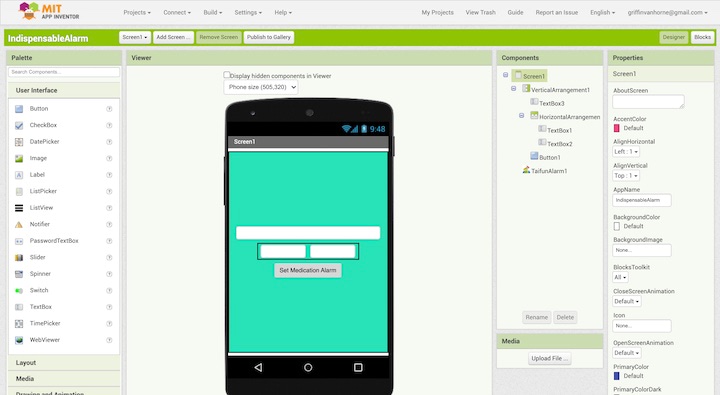
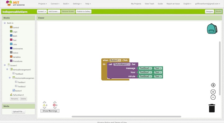
I decided to focus on building a standalone alarm clock app first, as this wouldn’t require interfacing with the ESP32, and would let me get up to speed with App Inventor. Once I got the hang of it, I would be able to tackle controlling the LED over Bluetooth, then attempt to merge the two to have the alarm clock control the LED over Bluetooth. I found this YouTube tutorial for making an alarm clock app with MIT App Inventor, and downloaded this alarm plugin for MIT App Inventor. Following the tutorial, I built an app that allows users to set an alarm with a message that will appear as a notification at the specified time.
When I tried to run this app using the MIT App Inventor Companion App in the Android Emulator, I got a message stating that the app did not have the proper permissions. I searched the error message, and found a post pointing back to the plugin’s documentation, which stated: “Note: You will have to build the app to be able to test it, because the companion app does not offer the required permission.” Based on this message, it looks like I won’t be able to test this alarm app until I can borrow a friend’s Android phone. Despite this setback, this was still a good intro to MIT App Inventor, and I feel much more confident about the rest of the week.
Through looking into this error code, I also found some helpful resources. Namely, I found a collection of App Inventor extensions, including a Bluetooth Low Energy extension and documentation to support it. I also found a couple posts on useful topics on the App Inventor forums, including two-way Bluetooth communication with Arduino, sending and receiving data to an ESP32 over BLE, and sending and receiving data from FirebaseDB with the ESP32. This last post will be useful when creating a medication history that can be referenced by the user.
May 8
During Global Open Time, I shared the current state of my project, and my plans for this week. I asked about others’ experience with MIT App Inventor, and Adrian pointed me to his Week 12 documentation.
Adrian also shared a link to the six-pack CNC, which was developed by Fab Lab Barcelona.
We discussed the ESP32 and the square “e-pad” in the center of the footprint. Rico shared the ESP32 Hardware Design Guidelines as well as this video which shows soldering through plated vias on the back of the board.
We also discussed milling double-sided boards. Important to note are the need for registration marks when milling them, then need to mirror the bottom layer before converting it to g-code, and the use of PCB rivets.
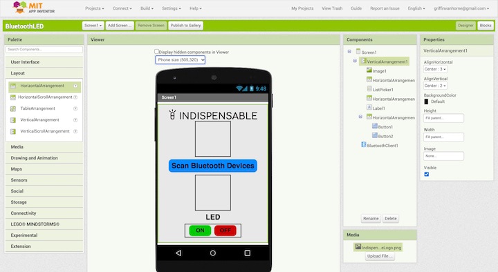
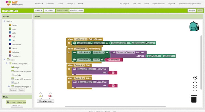
After Global Open Time, I followed this YouTube tutorial to build an MIT App Inventor app to turn on an LED over Bluetooth. There was also a link in the description to a GitHub repository that included the Arduino sketch created in the tutorial. Following this tutorial, I build an identical App Inventor project, and replicated the Arduino sketch.
char Incoming_value = 0;

void setup()
{
  Serial.begin(9600);
  pinMode(13, OUTPUT);
}

void loop()
{
  if(Serial.available() > 0)
  {
    Incoming_value = Serial.read();
    Serial.print(Incoming_value);
    Serial.print("\n");
    if(Incoming_value == '1')
      digitalWrite(13, HIGH);
    else if(Incoming_value == '0')
      digitalWrite(13, LOW);
  }
}
I uploaded the sketch to the ESP32, and scanned the App Inventor project’s QR code using the App Inventor Companion app, but was unable to find the ESP32 listed when I scanned for Bluetooth devices. Taking a step back, I realized that the tutorial was using the HC-05 Bluetooth module, and I would need to open the Bluetooth serial connection for the ESP32 to be discoverable. I followed this tutorial to be able to turn on and off a LED over Bluetooth using the same serial monitor app I used in week 13. I uploaded the following code to my ESP32 and was able to control the LED over Bluetooth!
#include "BluetoothSerial.h"

#if !defined(CONFIG_BT_ENABLED) || !defined(CONFIG_BLUEDROID_ENABLED)
#error Bluetooth is not enabled! Please run `make menuconfig` to and enable it
#endif

BluetoothSerial SerialBT;
int received;// received value will be stored in this variable
char receivedChar;// received value will be stored as CHAR in this variable

const char turnON ='a';
const char turnOFF ='b';
const int LEDpin = 26;

void setup() {
  Serial.begin(115200);
  SerialBT.begin("ESP32_Indispensable"); //Bluetooth device name
  Serial.println("The device started, now you can pair it with bluetooth!");
  Serial.println("To turn ON send: a");//print on serial monitor
  Serial.println("To turn OFF send: b"); //print on serial monitor
  pinMode(LEDpin, OUTPUT);

}

void loop() {
    receivedChar =(char)SerialBT.read();

  if (Serial.available()) {
    SerialBT.write(Serial.read());

  }
  if (SerialBT.available()) {

    SerialBT.print("Received:");// write on BT app
    SerialBT.println(receivedChar);// write on BT app
    Serial.print ("Received:");//print on serial monitor
    Serial.println(receivedChar);//print on serial monitor
    //SerialBT.println(receivedChar);//print on the app
    //SerialBT.write(receivedChar); //print on serial monitor
    if(receivedChar == turnON)
    {
     SerialBT.println("LED ON:");// write on BT app
     Serial.println("LED ON:");//write on serial monitor
     digitalWrite(LEDpin, HIGH);// turn the LED ON

    }
    if(receivedChar == turnOFF)
    {
     SerialBT.println("LED OFF:");// write on BT app
     Serial.println("LED OFF:");//write on serial monitor
      digitalWrite(LEDpin, LOW);// turn the LED off
    }


  }
  delay(20);
}
Knowing that this sketch functioned properly, I merged sections of it with sections of the sketch I had attempted to use the day before, to create the following:
#include "BluetoothSerial.h"

#if !defined(CONFIG_BT_ENABLED) || !defined(CONFIG_BLUEDROID_ENABLED)
#error Bluetooth is not enabled! Please run `make menuconfig` to and enable it
#endif

char Incoming_value = 0;

BluetoothSerial SerialBT;

void setup()
{
  pinMode(27, OUTPUT);
  Serial.begin(115200);
  SerialBT.begin("ESP32test"); //Bluetooth device name
  Serial.println("The device started, now you can pair it with bluetooth!");

}

void loop()
{
  if(Serial.available() > 0)
  {
    Incoming_value = Serial.read();
    Serial.print(Incoming_value);
    Serial.print("\n");
    if(Incoming_value == '0')
      digitalWrite(27, HIGH);
    else if(Incoming_value == '1')
      digitalWrite(27, LOW);
  }

}
Unfortunately, I still had the same issue, but I was unsure of what was causing it. I had other things to get done, so I decided to direct my attention elsewhere and come back to this later.
May 9
One potential issue with powering the pill case through a LiPo is that the battery would need to be recharged through an external charger when it’s depleted. In order to overcome this issue, I need to have the LiPo and a mini USB port connected to the board, along with components that will allow the LiPo to power the board under normal circumstances, but will allow the USB power supply to recharge the battery when it is plugged in. While this is a bit over my head, Adafruit’s Huzzah32 ESP32 Feather incorporates these components and provides a lot of documentation for the board, including details on power management and downloads, including the Eagle PCB files.
One major issue I noticed with the hall effect / gyro / OLED / RGB sketch was that the delays in the blinking function of the LEDs caused the gyroscope data to read out much more slowly. I followed this tutorial on the millis function, which can be used in place of the delay function, in order to allow the sketch to multitask. The tutorial was also provided in a written format, which was helpful. I instituted the millis function to blink the LED without using the delay function when the hall effect sensor is triggered.
#include <Adafruit_MPU6050.h>
#include <Adafruit_SSD1306.h>
#include <Adafruit_Sensor.h>

Adafruit_MPU6050 mpu;
Adafruit_SSD1306 display = Adafruit_SSD1306(128, 32, &Wire);

const int hallEffectPin = 25;
const int ledPinGreen = 26;
const int ledPinBlue = 27;
const int motor = 14;
int hallEffectState = 0;
int ledState = LOW;
int motorState = HIGH;

unsigned long previousMillis = 0;
const long interval = 500;


void setup() {

  pinMode(ledPinGreen, OUTPUT);
  pinMode(ledPinBlue, OUTPUT);
  pinMode(hallEffectPin, INPUT_PULLUP);
  pinMode(motor, OUTPUT);

  Serial.begin(115200);
  // while (!Serial);
  Serial.println("Indispensable Pill Case - MPU6050 & OLED Test");

  if (!mpu.begin()) {
    Serial.println("Sensor init failed");
    while (1)
      yield();
  }
  Serial.println("Found a MPU-6050 sensor");

  // SSD1306_SWITCHCAPVCC = generate display voltage from 3.3V internally
  if (!display.begin(SSD1306_SWITCHCAPVCC, 0x3C)) { // Address 0x3C for 128x32
    Serial.println(F("SSD1306 allocation failed"));
    for (;;)
      ; // Don't proceed, loop forever
  }
  display.display();
  delay(500); // Pause for 2 seconds
  display.setTextSize(1);
  display.setTextColor(WHITE);
  display.setRotation(0);

}

void loop() {
  // put your main code here, to run repeatedly:

  unsigned long currentMillis = millis();

  hallEffectState = digitalRead(hallEffectPin);

  if (hallEffectState == HIGH) {

    display.clearDisplay();
    display.setTextSize(1);
    display.setTextColor(WHITE);
    display.setCursor(0, 0);
    // Display static text
    display.println("*** INDISPENSABLE ***");
    display.println("---------------------");
    display.println("    REMEMBER WHAT    ");
    display.println("    EMPOWERS YOU     ");
    display.display();


    digitalWrite(ledPinGreen,LOW);
    digitalWrite(ledPinBlue,HIGH);
    digitalWrite(motor, LOW);
    delay(100);
    digitalWrite(ledPinGreen,HIGH);
    digitalWrite(ledPinBlue,HIGH);
    digitalWrite(motor, LOW);
    delay(900);
  }

  else {

    sensors_event_t a, g, temp;
    mpu.getEvent(&a, &g, &temp);

    display.clearDisplay();
    display.setCursor(0, 0);

    Serial.print("Gyroscope ");
    Serial.print("X: ");
    Serial.print(g.gyro.x, 1);
    Serial.print(" rps, ");
    Serial.print("Y: ");
    Serial.print(g.gyro.y, 1);
    Serial.print(" rps, ");
    Serial.print("Z: ");
    Serial.print(g.gyro.z, 1);
    Serial.println(" rps");

    display.println("*** INDISPENSABLE ***");
    display.print("       X: ");
    display.print(g.gyro.x, 1);
    display.println("");
    display.print("       Y: ");
    display.print(g.gyro.y, 1);
    display.println("");
    display.print("       Z: ");
    display.print(g.gyro.z, 1);

    display.display();
    delay(100);

    if (currentMillis - previousMillis >= interval) {
    // save the last time you blinked the LED
    previousMillis = currentMillis;

    // if the LED is off turn it on and vice-versa:
    if (ledState == LOW) {
      ledState = HIGH;
      motorState = HIGH;
    } else {
      ledState = LOW;
      motorState = LOW;
    }

  }


    // set the LED with the ledState of the variable:
    digitalWrite(ledPinBlue, ledState);
    digitalWrite(motor, motorState);
  }
}
When attempting to load the Fade example sketch, I kept getting the error: “‘analogWrite’ was not declared in this scope.” Upon further research, I this page which informed me that the ESP32 doesn’t use analogWrite, but instead uses “ledcAttachPin.” This isn’t a simple cut and paste solution, as pins need to be assigned to channels for ledc to work properly. I was pointed to this page about PWM with the ESP32 from, you guessed it, Random Nerd Tutorials, which explained things fairly well. I managed to get together a very basic sketch to fade the LED.
int led_gpio = 26; // the PWM pin the LED is attached to
int brightness = 100;    // how bright the LED is
int fadeAmount = 1;    // how many points to fade the LED by

// the setup routine runs once when you press reset:
void setup() {
  ledcAttachPin(led_gpio, 0); // assign a led pins to a channel

  // Initialize channels
  // channels 0-15, resolution 1-16 bits, freq limits depend on resolution
  // ledcSetup(uint8_t channel, uint32_t freq, uint8_t resolution_bits);
  ledcSetup(0, 4000, 8); // 12 kHz PWM, 8-bit resolution
}

// the loop routine runs over and over again forever:
void loop() {
  ledcWrite(0, brightness); // set the brightness of the LED

  // change the brightness for next time through the loop:
  brightness = brightness + fadeAmount;

  // reverse the direction of the fading at the ends of the fade:
  if (brightness <= 100 || brightness >= 254) {
    fadeAmount = -fadeAmount;
  }
  // wait for 30 milliseconds to see the dimming effect
  delay(20);
}
Unfortunately, this fade sketch still used delays, and I was unable to merge it with the main sketch shown above. I couldn’t figure out what was wrong, so I decided to move on for now.
May 10
During Spencer’s office hours, the other students and I shared our experiences during the past week. This proved to be very helpful, as the others were also using the ESP32 and MIT App Inventor. Xiaolin shared a link to the documentation of a student who controlled an RGB LED connected to an ESP32 over Bluetooth Low Energy (BLE) using the Blynk app.
I shared the issue I was having with Bluetooth sketch with the group, and Nick offered a solution. Because I was initializing two separate serial connections, I needed to make sure that I was referencing the proper one. The way my sketch was set up, I was having the ESP serial read itself, rather than reading the Bluetooth serial. Making these changes was very simple, and it solved the problems I was experiencing!
#include "BluetoothSerial.h"

#if !defined(CONFIG_BT_ENABLED) || !defined(CONFIG_BLUEDROID_ENABLED)
#error Bluetooth is not enabled! Please run `make menuconfig` to and enable it
#endif

char Incoming_value = 0;

BluetoothSerial SerialBT;

void setup()
{
  pinMode(27, OUTPUT);
  Serial.begin(115200);
  SerialBT.begin("ESP32test"); //Bluetooth device name
  Serial.println("The device started, now you can pair it with bluetooth!");

}

void loop()
{
  if(SerialBT.available() > 0)
  {
    Incoming_value = SerialBT.read();
    Serial.print(Incoming_value);
    Serial.print("\n");
    if(Incoming_value == '0')
      digitalWrite(27, HIGH);
    else if(Incoming_value == '1')
      digitalWrite(27, LOW);
  }

}
May 12
I made another modification to the main test sketch to cause the OLED to change what it display based on the state of the LED.
#include <Adafruit_MPU6050.h>
#include <Adafruit_SSD1306.h>
#include <Adafruit_Sensor.h>

Adafruit_MPU6050 mpu;
Adafruit_SSD1306 display = Adafruit_SSD1306(128, 32, &Wire);

const int hallEffectPin = 25;
const int ledPinGreen = 26;
const int ledPinBlue = 27;
const int motor = 14;
int hallEffectState = 0;
int ledState = LOW;
int motorState = HIGH;

unsigned long previousMillis = 0;
const long interval = 500;


void setup() {

  pinMode(ledPinGreen, OUTPUT);
  pinMode(ledPinBlue, OUTPUT);
  pinMode(hallEffectPin, INPUT_PULLUP);
  pinMode(motor, OUTPUT);

  Serial.begin(115200);
  // while (!Serial);
  Serial.println("Indispensable Pill Case - MPU6050 & OLED Test");

  if (!mpu.begin()) {
    Serial.println("Sensor init failed");
    while (1)
      yield();
  }
  Serial.println("Found a MPU-6050 sensor");

  // SSD1306_SWITCHCAPVCC = generate display voltage from 3.3V internally
  if (!display.begin(SSD1306_SWITCHCAPVCC, 0x3C)) { // Address 0x3C for 128x32
    Serial.println(F("SSD1306 allocation failed"));
    for (;;)
      ; // Don't proceed, loop forever
  }
  display.display();
  delay(500); // Pause for 2 seconds
  display.setTextSize(1);
  display.setTextColor(WHITE);
  display.setRotation(0);

}

void loop() {
  // put your main code here, to run repeatedly:

  unsigned long currentMillis = millis();

  hallEffectState = digitalRead(hallEffectPin);

  if (hallEffectState == HIGH) {

    display.clearDisplay();
    display.setTextSize(1);
    display.setTextColor(WHITE);
    display.setCursor(0, 0);
    // Display static text
    display.println("*** INDISPENSABLE ***");
    display.println("---------------------");
    display.println("    REMEMBER WHAT    ");
    display.println("    EMPOWERS YOU     ");
    display.display();


    digitalWrite(ledPinGreen,LOW);
    digitalWrite(ledPinBlue,HIGH);
    digitalWrite(motor, LOW);
    delay(100);
    digitalWrite(ledPinGreen,HIGH);
    digitalWrite(ledPinBlue,HIGH);
    digitalWrite(motor, LOW);
    delay(900);
  }

  else {

    sensors_event_t a, g, temp;
    mpu.getEvent(&a, &g, &temp);

    display.clearDisplay();
    display.setCursor(0, 0);

    Serial.print("Gyroscope ");
    Serial.print("X: ");
    Serial.print(g.gyro.x, 1);
    Serial.print(" rps, ");
    Serial.print("Y: ");
    Serial.print(g.gyro.y, 1);
    Serial.print(" rps, ");
    Serial.print("Z: ");
    Serial.print(g.gyro.z, 1);
    Serial.println(" rps");

    display.println("*** INDISPENSABLE ***");
    display.print("       X: ");
    display.print(g.gyro.x, 1);
    display.println("");
    display.print("       Y: ");
    display.print(g.gyro.y, 1);
    display.println("");
    display.print("       Z: ");
    display.print(g.gyro.z, 1);

    display.display();
    delay(100);

    if (currentMillis - previousMillis >= interval) {
    // save the last time you blinked the LED
    previousMillis = currentMillis;

    // if the LED is off turn it on and vice-versa:
    if (ledState == LOW) {
      ledState = HIGH;
      motorState = HIGH;
    } else {
      ledState = LOW;
      motorState = LOW;
    }

  }


    // set the LED with the ledState of the variable:
    digitalWrite(ledPinBlue, ledState);
    digitalWrite(motor, motorState);
  }
}
This demonstrates that more than just the LED is changing when the hall effect sensor is triggered, but in reality, I’ll need to add much more logic to the sketch for this surface-level change to be useful. I’m starting to get a bitter picture of what will need to be done moving forward, however. Right now I have three separate sketches:
- The main test sketch that uses the IMU and hall effect sensor as inputs, and the RBG LED, OLED, and motor as outputs.
- The Bluetooth serial sketch that interfaces with the MIT App Inventor app, and changes the state of the LED
- The LED fade sketch
These sketches will need to be merged together in a way where in the board’s resting state, the LED will fade green without using the delay function. When the mobile app triggers the medication reminder, a message will be sent to the pill case over Bluetooth that will change the device to an alert state, where pleasant visual, auditory, and haptic feedback will be transmitted to the user through the output devices. In this alert state, readings from the hall effect sensor will be taken, and when the magnet in the pill case door is on top of the hall effect sensor, gyroscope readings will be taken. When the gyroscope is moved beyond a certain threshold with the door open, the pill case will send data back to the mobile app indicating that the pills have been taken, and the case will return to its resting state.