Week 7: Computer-Controlled Machining
This week was an exciting one, as I had built furniture in the past, but I had never used a large CNC router. I immediately knew that I wanted to build a chair. While I was able to quickly generate a design, my timeline was derailed by limitations at the space due to COVID precautions. Nonetheless, I’ve pushed this week’s assignment as far as I can given the current situation.
Mar 10
During the lecture, Neil highlighted a number of manufacturing processes, techniques, and guidelines. He also mentioned some projects that were utilizing these technologies. One that stood out to me was Opendesk, which is a global platform that connects CNC furniture designers, CNC fabricators, and customers. Digital fabrication enables designers to disseminate and monetize their creations in new ways, and Opendesk demonstrates how local CNC manufacturing can enable global distribution.
Mar 11
At Dassault, Spencer gave a great tutorial for the Shopbot CNC router and VCarve CAM software. He discussed how to import files into VCarve, nest multiple parts in one job, add “dogbone” fillets, set up tool paths, and export the file to the Shopbot g-code sender software. He also covered how set the machine’s origin coordinates, attach the material to the bed of the router, insert a cutting tool, adjust the dust collector, start the cutting operation, and stop it when necessary.
Mar 12
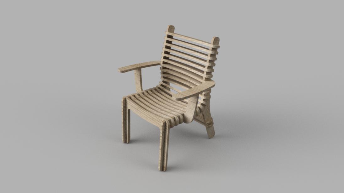
Before I began modeling my chair, I collected some inspiration from the internet. A few designs that stood out to me were this CNC reimagining of the Eames molded plywood lounge chair, the Interconecto Bench by Terraform Design, the Curvy chair by CNCflatpack, the Facet Chair by Unto This Last, and Denis Fuzii’s Valovi Chair for Opendesk. The Valovi Chair ended up being my main design inspiration, and I sought to use this anatomy to design a comfortable armchair. I also referenced an excerpt from Henry Dreyfuss’ The Measure of Man (1959), which still serves as a bible for human factors engineers to this day. If I were to have more time to focus on designing the chair, I would attempt to recreate the iconic Eames lounge chair and ottoman. After several iterations and design reviews, I was very happy with my chair.
The Center for Cubits and Atoms
Chair Files
Mar 15
Now that my design was finalized, my plan was laser cut a small-scale prototype before cutting the full-scale version to test for any design flaws not visible in the CAD model. To modify the design for laser cutting, I could have compensated for kerf in CAD, or followed this tutorial to account for it using Fusion 360’s CAM Workspace. However, Spencer suggested that as this is just a scale model, I shouldn’t worry about the kerf compensation and should instead spend the time on learning the Shopbot toolchain and setting up my tool paths. This ended up being very good advice, as every step of the process took much longer than expected. With this in mind, the plan was to set up my vector files in a 4’ x 8’ cutting area using V Carve, then export this as a vector file so I could laser cut the scale model before setting up the tool paths and cutting out the full-sized chair.
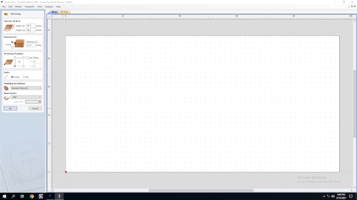
The first step was to open a new file in V Carve and set the dimensions to be 4’ x 8’.
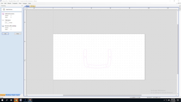
I then loaded the vectors files representing each unique part of the chair into the V Carve file. Many of these files actually consisted of multiple, unjoined vectors, so I had to use the “Join Vectors” tool to combine them into one closed vector.
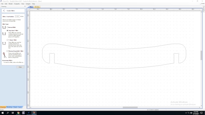
From there, I added “dog bones” to the concave corners of every slot where another piece of wood would interface with the part. As I would be using a 1/4” end mill to cut out the chair, I could not achieve any concave corners with a radius tighter than 1/4”. This would mean that the two intersecting pieces would not be able to fully fit together. In order to solve this issue, you can add a small circular cutout to the part, where the circle is the radius of the cutting tool and the center of the circle is at the corner. This geometry is called a “dog bone,” and V Carve has a tool that lets you easily add them to your parts by simply clicking on the corner you would like to modify.
Once the parts were modified so they could fit together properly, I used the Array tool to create duplicates of the parts of which multiples were required to build the chair.
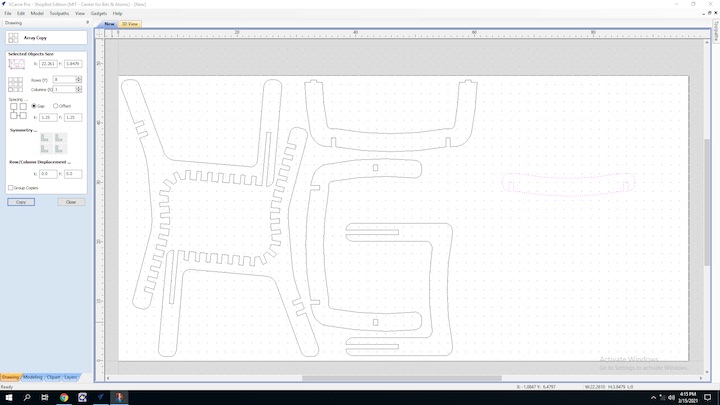
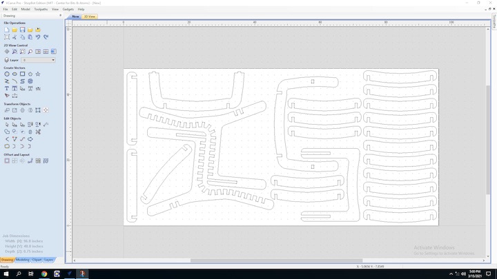
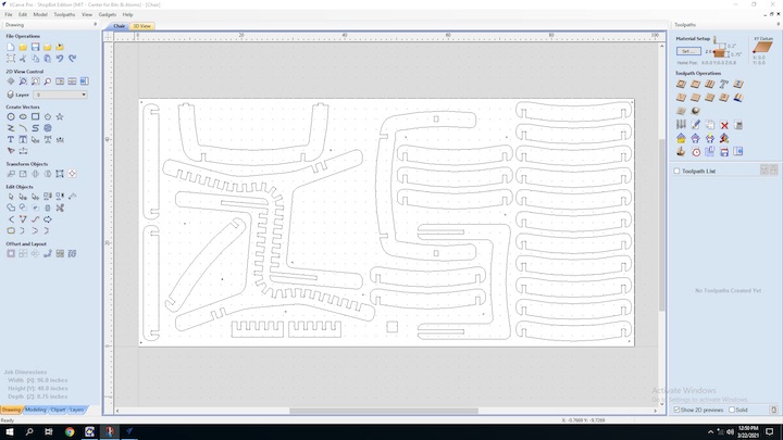
I now had all of the parts necessary to assemble the chair, I needed to arrange them so they could all fit within a 4’ x 8’ sheet of plywood.
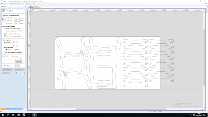
While V Carve does have an “AutoNest” tool, it doesn’t work very well.
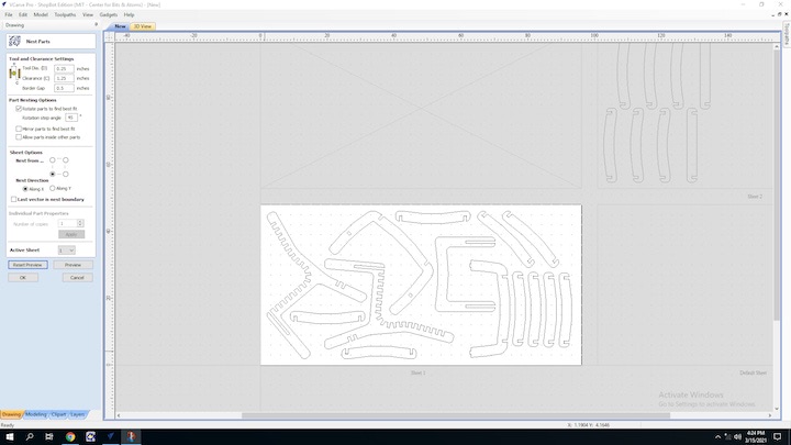
I spent the better part of an hour trying to manually nest the parts as best as I could, while still leaving enough space for the 1/4” tool path around each part, along with 3/4” of space between the tool paths of adjacent parts. Eventually, I got all of the parts to nest cleanly!
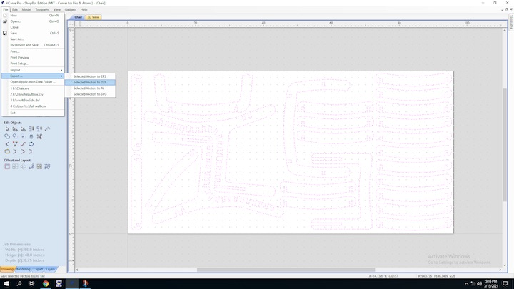
Finally, I exported the V Carve file as a .DXF so I could scale it down and laser cut it.
Chair Files
Mar 22
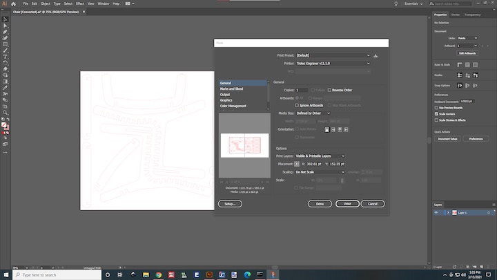
I opened the DXF file in Illustrator on the computer connected to the laser cutter at the 3D Experience Lab.
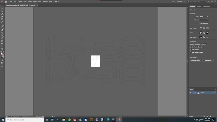
In order for this scale model to function properly, I had to measure the laser cutting plywood, and scale the vector file so the slots were the width of this thinner material. To do this, I simply divided the thickness of laser cutting plywood by the thickness of the CNC plywood, then scaled the vector file by this number.
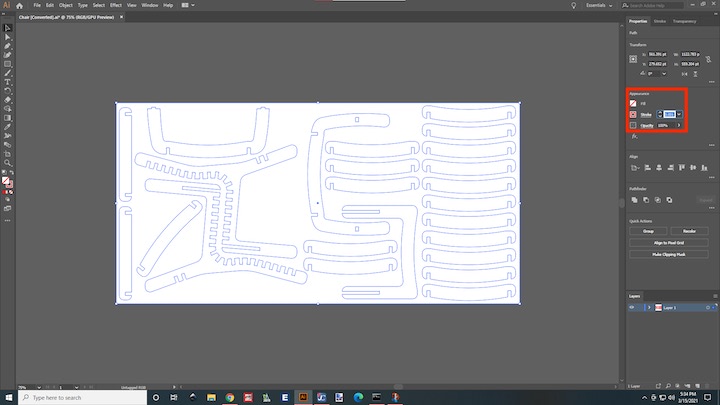
I also adjusted the stroke weight to 0.001 mm and the stroke color to pure red in order for the file to be compatible with the Job Control software. Once these changes were made, I clicked print, and chose the laser cutter as the printer.
Having the laser cutter chosen as the printer in Illustrator automatically opens the file in Epilog Job Control, which is the software that interfaces with the laser cutter.
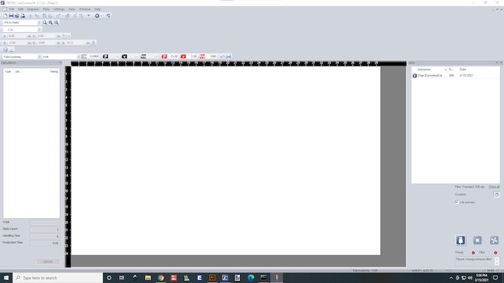
Once the file is loaded into Job Control, it needs to be selected from the browser on the right of the screen for it to appear in the main window.
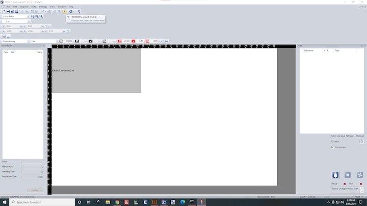
Pressing the eye icon in the toolbar at the top of the screen makes the vector visible, which helps with alignment before sending the job to the laser cutter.
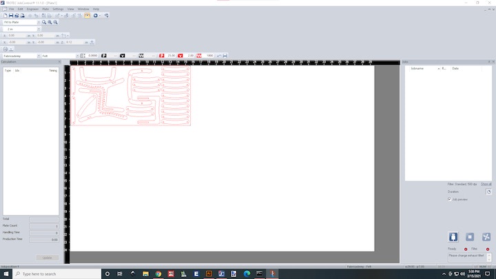
Once everything was aligned properly, I loaded the material into the laser cutter, used the automatic z-height adjustment, and sent the file to the laser cutter.
Mar 22
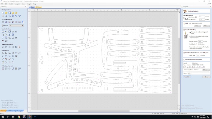
With all of the vectors laid out on the material, I set up a tool path to make shallow holes on the surface of the plywood to mark locations where I can screw down wood screws to serve as work holding and to prevent the wood from moving during the milling operation. I clicked on the Toolpath icon in the top right of the screen, which brought up the Toolpath Menu.
I was then prompted to select the vector paths to be cut, the milling operation type, and the milling tool. I selected the work holding holes, a drilling operation, and a 1/4” depth.
I then saved this toolpath to a file, which automatically opened up the ShopBot Command Console.
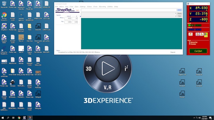
I then turned on the ShopBot, raised the spindle, inserted the correct tool, zeroed the X, Y, and Z axes, turned on the spindle, turned on the dust collection, and performed the work holding operation. Once the operation was complete, I used wood screws to secure the plywood sheet to the waste board with wood screws. With the material properly fastened, I ran two small test cuts. The first was to test how parts with different slot thicknesses would intersect with each other.
The second test was a 2” x 2” (50.8 mm x 50.8 mm) square to measure the dimensional accuracy of parts cut on the ShopBot.


To measure the runout of the spindle, we can subtract the actual width of the part from the width specified in the file, and divide that difference by two. Given the actual dimensions of the test piece, the runout of the machine is 0.18 mm in one axis, and 0.07 mm in the other axis. Unfortunately, I’m not positive which axis is which.
Test Part Files
Mar 25
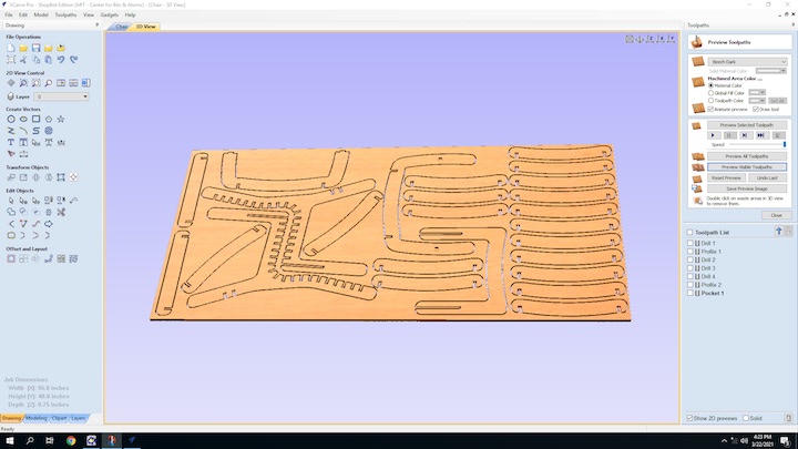
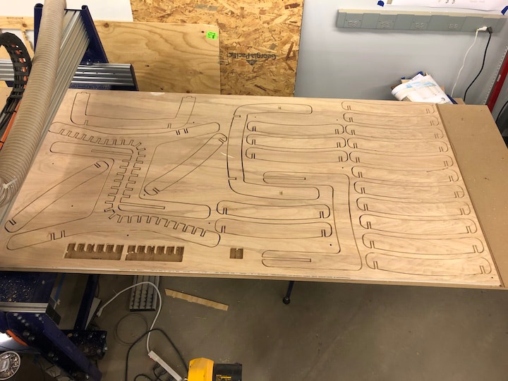
Now that I confirmed that the slot thickness I had used in my design will fit properly, I was all ready do go ahead with my routing out design. Similarly as I did before, I selected the vector paths to be cut, set the cutting tool as a 1/4”, 2-fluted, down-cut, square-end end mill, and set the cut settings to cut through the entire material depth. I also set up “tabs,” which leave small gaps in the final pass of the tool path, and prevent the parts from coming loose and getting damaged while the part is still being cut. These tabs are then hammered out with a chisel when the operation has completed. Once the tabs were set up, I clicked “Preview Toolpaths” to see a 3D model of the material with the tool paths superimposed.
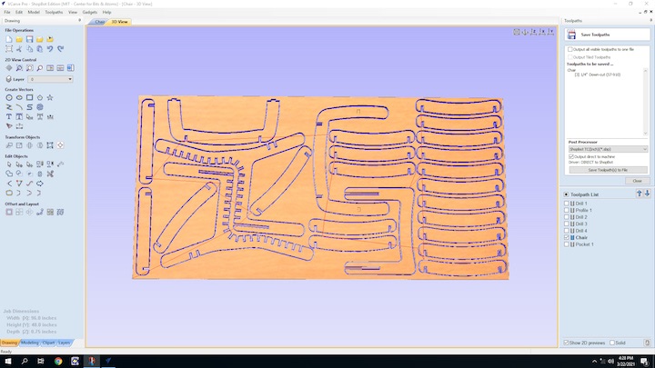
Satisfied with the preview, I clicked “Save Toolpaths.”
The ShopBot Command Console opened up as before, and I followed the same steps to set up the machine and register it to the material. Once everything was set up, I pressed “Start” and the milling operation began.
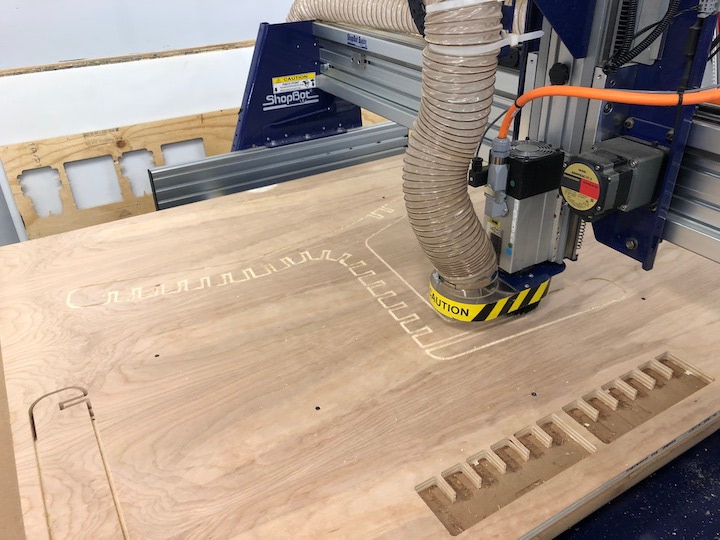
The operation took about two hours to complete.
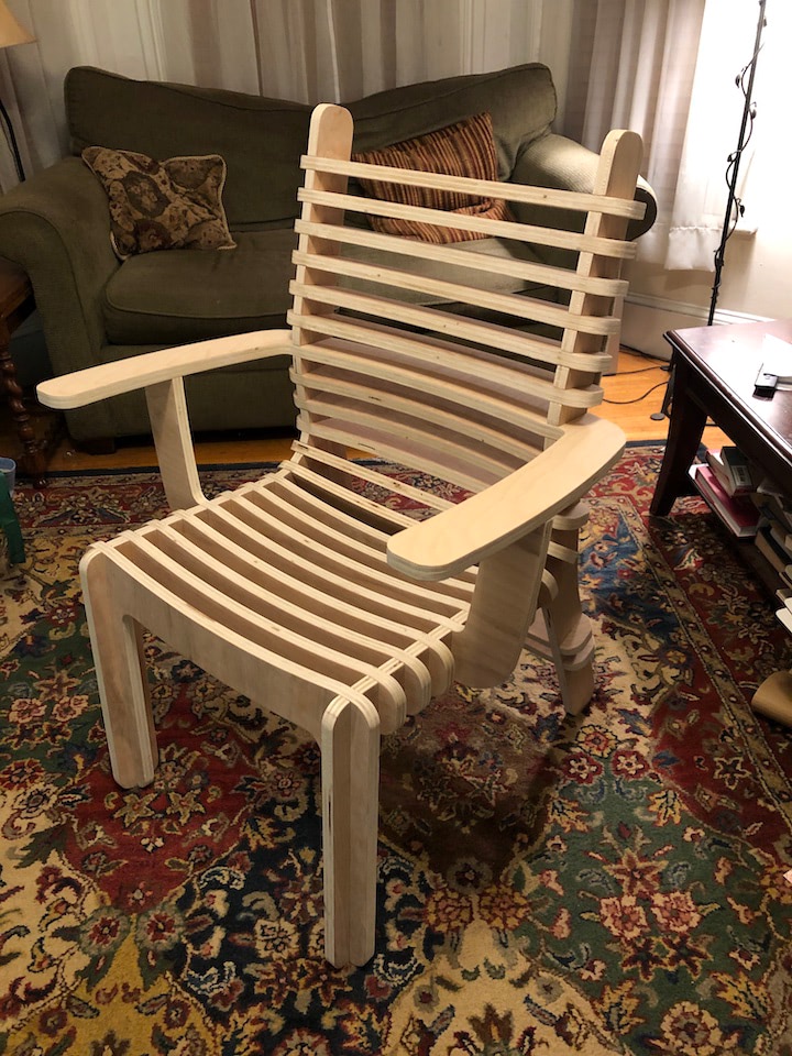
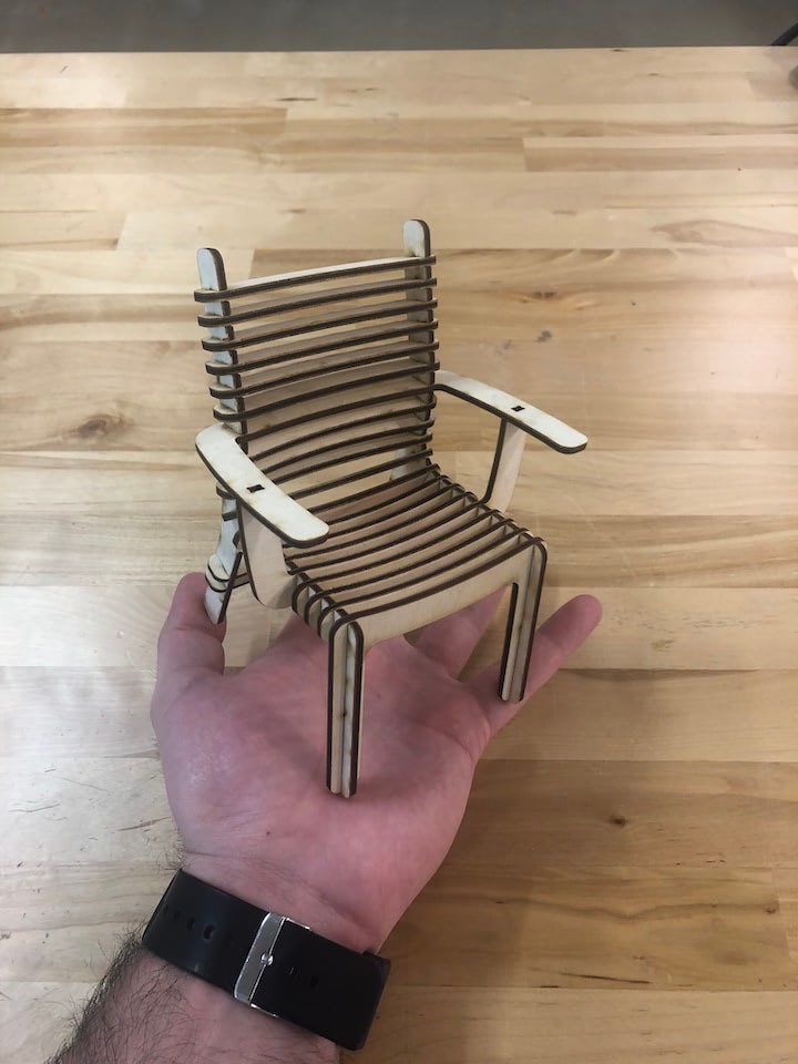
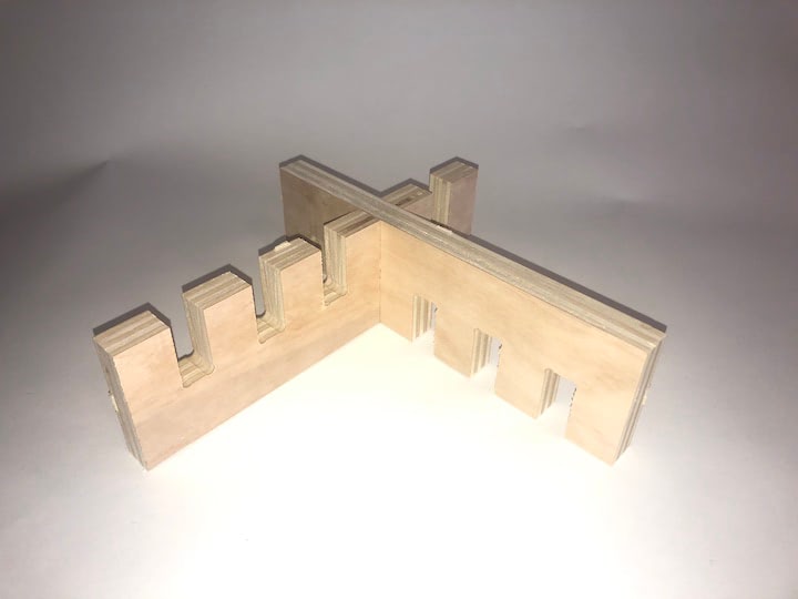
Once it was complete, I used a hammer and a chisel to separate the parts from the waste material. Once these parts were removed, I sanded down each part separately, which took hours, but was well worth it, as it gave the milled edges a smooth feel. Finally, I brought the parts home and assembled them into the finished piece!