Week 3: Computer Controlled Cutting
This week I worked with the laser cutter to characterize its kerf, create a press-fit animal kit, and test components for an enclosure for the 3018 CNC router. I also designed a logo for my final project and cut it out on the vinyl cutter.
Laser Cutter Kerf Characterization
The first step to creating laser-cut structures was to characterize the kerf of the laser so the panels could fit together perfectly. I first created a sketch that incorporated parameters for the thickness of the material and the kerf of the laser.

I then extruded the sketch the thickness of the material. This helped me better visualize the parts, and create a clean sketch on the top face of the parts free of any construction lines.

At this point, I could go back into my parameters and change dimensions such as the overall size of the parts, the material thickness, or the kerf of the laser.

I started with the kerf characterization data that my lab mates generated for the 1/4” plywood, but the number they had come up with wasn’t perfectly accurate. Fortunately, every failed test is a data point, and I was able to narrow in on the true kerf after a collecting a number of poorly fitting test pieces.

One thing that was a little counterintuitive was that in my CAD file, the width of the model was =PartWidth+Kerf, and the width of the slots for the press-fit parts were =MaterialThickness-Kerf. If the resultant laser-cut test part was wider than the CAD model width, that means the kerf parameter is too large, rather than too small, as the CAD model is compensating for the kerf of the laser. If two press fit parts are too loose, the kerf parameter should be be decreased. On the first test, I misinterpreted the press fit parts being too loose as indicating that the kerf parameter should be increased, and the second test part was worse than the first. At that point, I realized I was moving in the wrong direction, and began narrowing in on the kerf, eventually getting to a value of 0.25 mm.


I latter replicated this process with 1/4” clear acrylic at the Cambridge Hackspace. I felt that the most promising of the press-fit joints was the pin joint, so I made some modifications to my file to allow the pin to be held in place by a nut and bolt.

In order to speed up the process of identifying the kerf, I cut out a series of small squares, then compared their width to the dimensions of the CAD file to characterize the kerf.

Cambridge Hackspace’s laser was a bit out of alignment, and the kerf was slightly larger, at 0.275 mm. This test was a resounding success, and I was very happy with the results.


Joint Test Files:
CNC Enclosure
The end goal of this development was to create an enclosure for my Sainsmart Genmitsu 3018 Pro CNC router. The router will live in a small workshop in my house, so I’d like to minimize the dust and noise as much as possible. I spent a fair amount of time designing the general form of the enclosure and choosing the optimal materials in parallel while I was characterizing the kerf and running small scale tests of the joints I will be using for the enclosure.

Press-Fit Kit: Lil’ Guys
Building off this experience, I moved on to creating a modular kit to allow for the creation of a custom laser-cut animal model. I designed three sets of legs, two bodies, and two heads. This is just a proof of concept, and this concept could be expanded to create a wide variety of animals. First, I created a fully constrained, parametric sketch incorporating the the information from my kerf characterization tests.

Once again, I extruded this sketch the thickness of the material, and created a clean sketch on the top face of the parts, then exported this sketch as a .dxf.

I opened this file in Adobe Illustrator, and set the line thickness to 0.001 pt, and the line color to pure red. I then “printed” the file to the Trotec laser cutter at the Dassault 3D Experience Lab. In order to minimize the amount of material waste, I nested the objects together as closely as possible.

Thanks to the work I had done to characterize the kerf of the laser, the parts fit together perfectly. As you can see, the parts can be swapped out for each other to create the Lil Guy of your dreams.


Lil’ Guys Files:
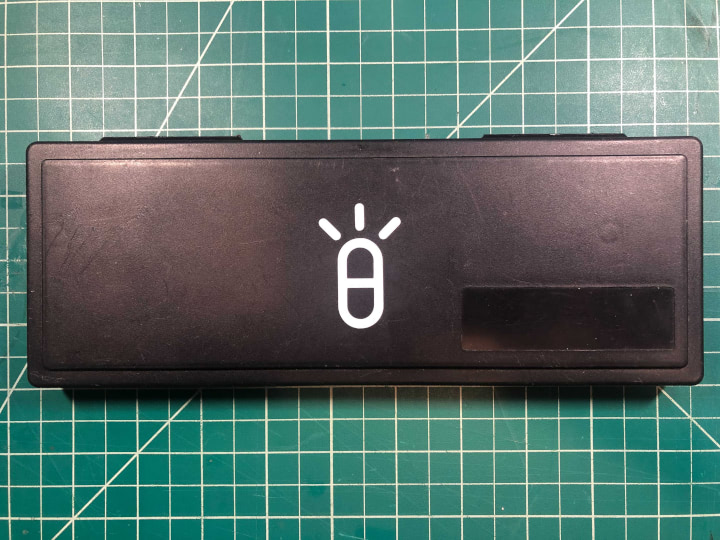
Vinyl Cutter: Indispensable Logo
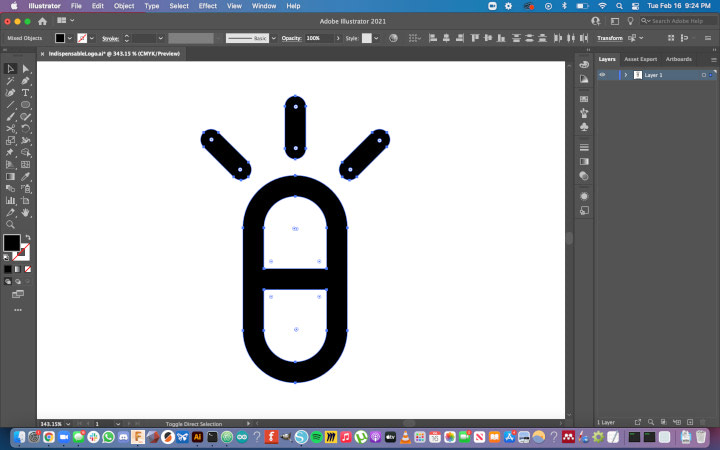
For the vinyl cutting portion of the assignment, I designed a logo for my final project, and cut it our on my Silhouette Cameo vinyl cutter. I have pasted it on the back of my phone and on the case of my calipers so I see it every day, and can figure out if I get sick of it. Once I had designed the general shape of the logo in Adobe Illustrator, I had to modify it to be compatible with the vinyl cutter.
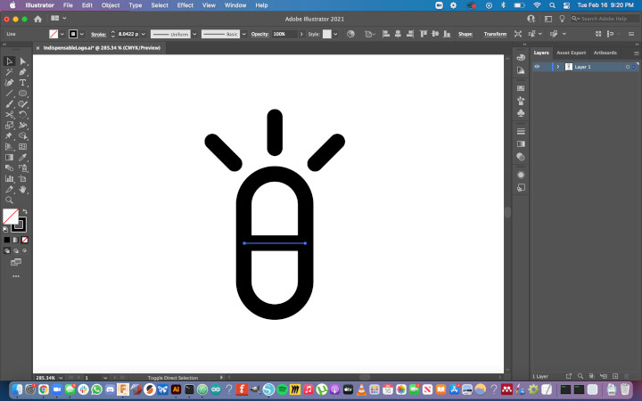
First, I had to join the overlapping lines to make them one cohesive shape.
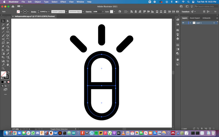
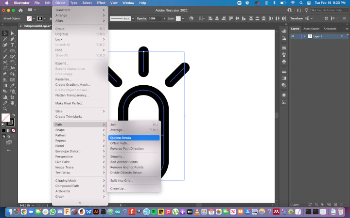
Second, I needed to outline the strokes. Even though the design appears to have thickness, if I exported the file without outlining the strokes, the vinyl cutter would cut straight down the center of each line in the design, rather than cutting the inside and outside perimeters.
From there, I exported the file as a .dxf, and opened it in Silhouette Studio.
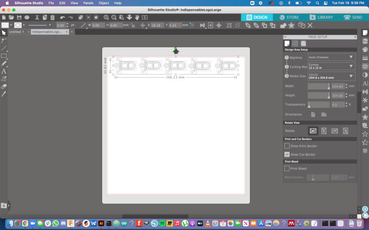
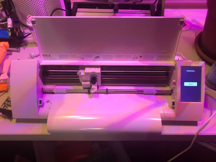
I cut out the design on my Silhouettte Cameo.
Once cut, I weeded the vinyl, and prepared a strip of transfer sheet to stick to the front of the decals.
![]()
Once I attached the transfer sheet to the decals, I split the strip into five separate designs.
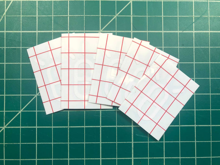
I’ve attached these decals to several objects that I interact with every day. This will help me figure out if I learn to love the design or get sick of it, so I iterate as quickly as possible.