Week 12: Output Devices
My work this week was relatively limited, as I had a lot of work to do for my day job. The goal was to create an ESP32-based board with all of the input and output devices required for my final project. The form factor will change to fit inside the enclosure, but fabricating this board will be a large milestone, as it can serve as a testbed for developing the code for the pill case.
Apr 21
In lecture, Neil highlighted a number of output devices. The piezo buzzer and DC motor were of particular interest to me, as they could serve to notify the user that it’s time to take their pills.
Apr 22
In our local node review, we discussed the lecture and how we can apply those devices to our projects. I discussed my specific application, and how the output devices will make this possible. Other students discussed using an OLED display, and I was inspired by how small a 32x128 OLED is, so I decided to include one on my board as well.
After the lecture, I ordered the necessary output devices: The 10mm x 2.7mm DC vibration motor (3V 85mA 12000RPM) (schematic), the CMT-8530S-SMT-TR magnetic buzzer (datasheet), and the SSD1306 0.96” OLED display (datasheet).
Apr 27
Once I had completed my research on the output devices I would be using, I began to design my circuit board. I began by referincing the Barduino 2.0. This repo included annotated schematics and Eagle design files, which was very helpful to get started. I also found this documentation from a Fab Academy student that worked with the board. I referenced this pinout diagram from Random Nerd Tutorials, but also found [another pinout diagram] that had conflicting information. After some more research, I determined that this second pinout was innacurate.
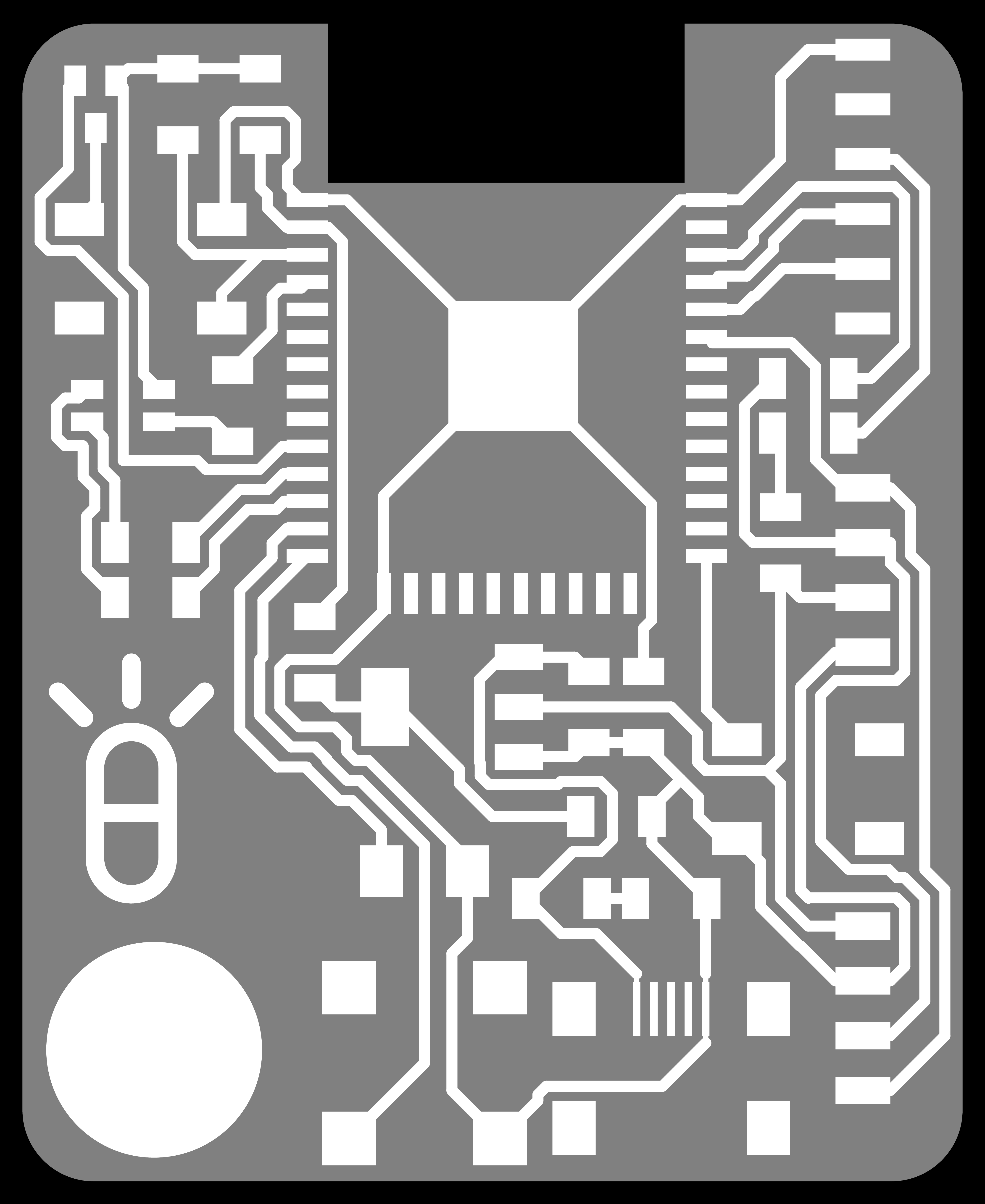
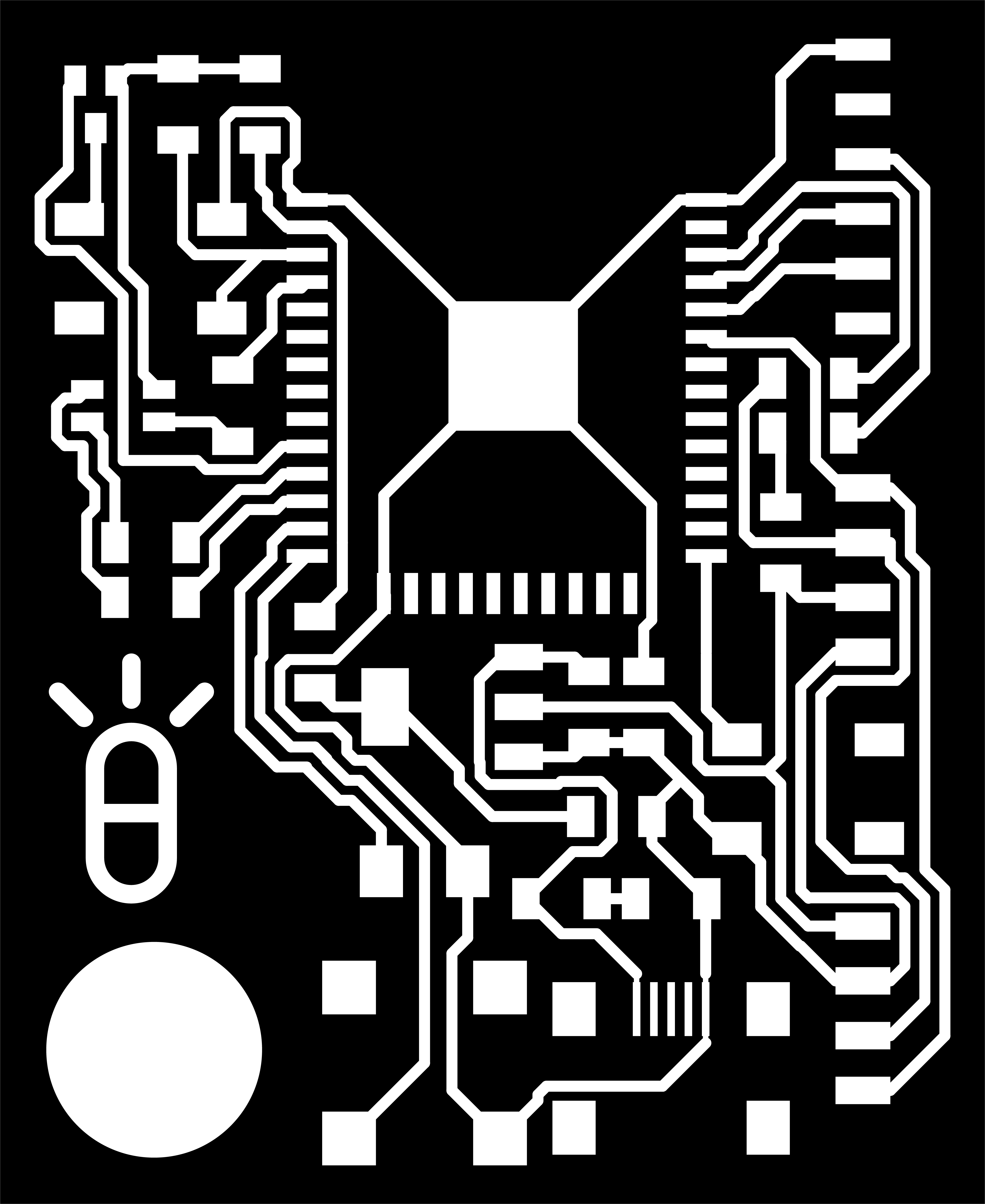
With this research out of the way, I designed the board in Eagle, then followed the same post-processing workflow as before, where I exported all layers as one .dxf file to Illustrator, then created the perimeter file and exported the layers as .png files.

Apr 28
I then imported the .png files into Mods, imput the same parameters as before, and exported the .nc files.
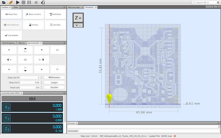
I then milled the board on the 3018 using the 0.15” PreciseBits tapered-stub end mill.
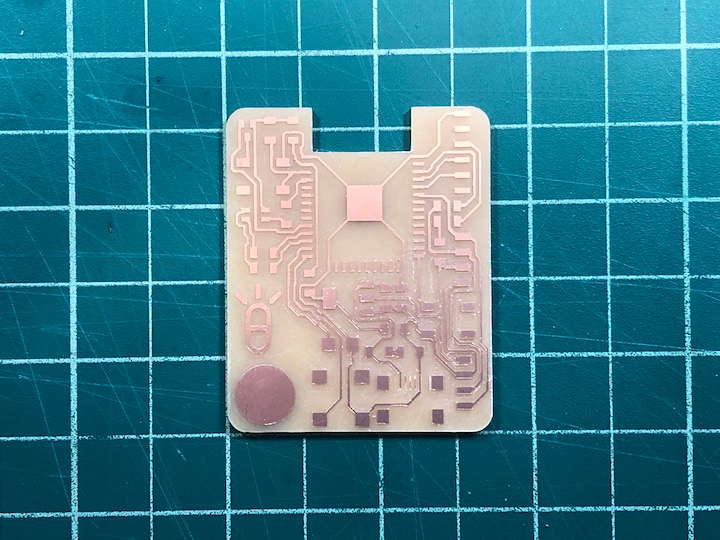
I then soldered on the components onto the board, and it went without a hitch.
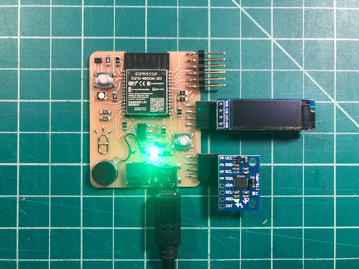
I plugged the board in to gice it a smoke test, and no magic smoke was released.
Apr 30
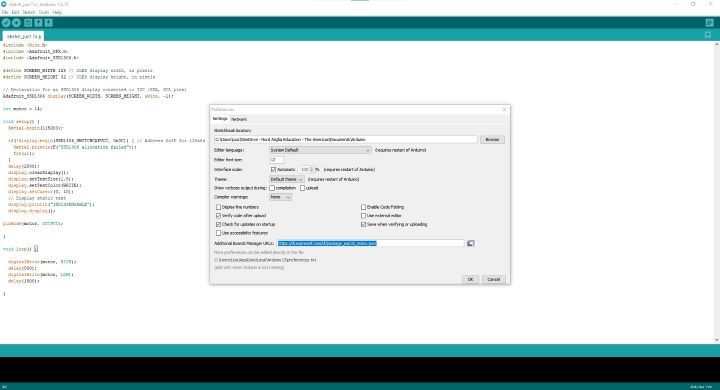
I followed these instructions to program the ESP32 on the Arduino IDE. First I added https://dl.espressif.com/dl/package_esp32_index.json to the “Additional Boards Manager URLs” field in the Preferences menu.
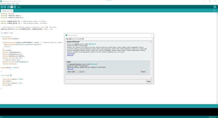
I then opened the Boards Manager, searched for “ESP32,” and downloaded the latest version.
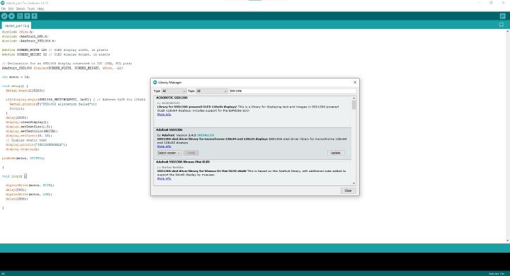
I then opened the Library Manger and downloaded Wire.h, Adafruit_GFX.h, and Adafruit_SSD1306.h.
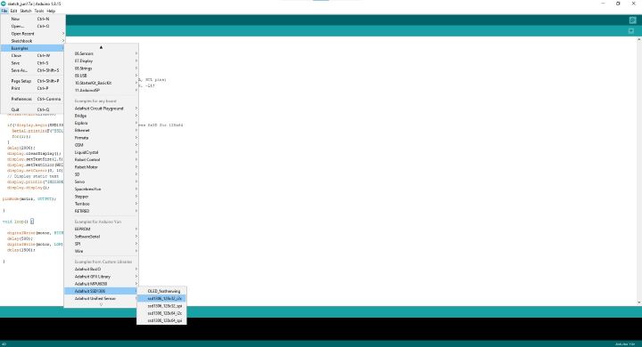
I opened the Examples menu, then Adafruit SSD1306, and chose ssd1306_128x32_i2c.ino.
I ran this test sketch, and was able to view the Adafruit demo reel on the OLED. Now that I could confirm the OLED was functioning properly, I made adjustments to the code to show the project name on the OLED and to make the vibration motor pulse at the same time. You can find this sketch below:
#include <Wire.h>
#include <Adafruit_GFX.h>
#include <Adafruit_SSD1306.h>

#define SCREEN_WIDTH 128 // OLED display width, in pixels
#define SCREEN_HEIGHT 32 // OLED display height, in pixels

// Declaration for an SSD1306 display connected to I2C (SDA, SCL pins)
Adafruit_SSD1306 display(SCREEN_WIDTH, SCREEN_HEIGHT, &Wire, -1);

int motor = 14;

void setup() {
  Serial.begin(115200);

  if(!display.begin(SSD1306_SWITCHCAPVCC, 0x3C)) { // Address 0x3D for 128x64
    Serial.println(F("SSD1306 allocation failed"));
    for(;;);
  }
  delay(2000);
  display.clearDisplay();
  display.setTextSize(1.5);
  display.setTextColor(WHITE);
  display.setCursor(0, 10);
  // Display static text
  display.println("INDISPENSABLE");
  display.display();

pinMode(motor, OUTPUT);

}

void loop() {

  digitalWrite(motor, HIGH);
  delay(500);
  digitalWrite(motor, LOW);
  delay(1500);

}
Both the OLED and the vibration motor worked without issue.
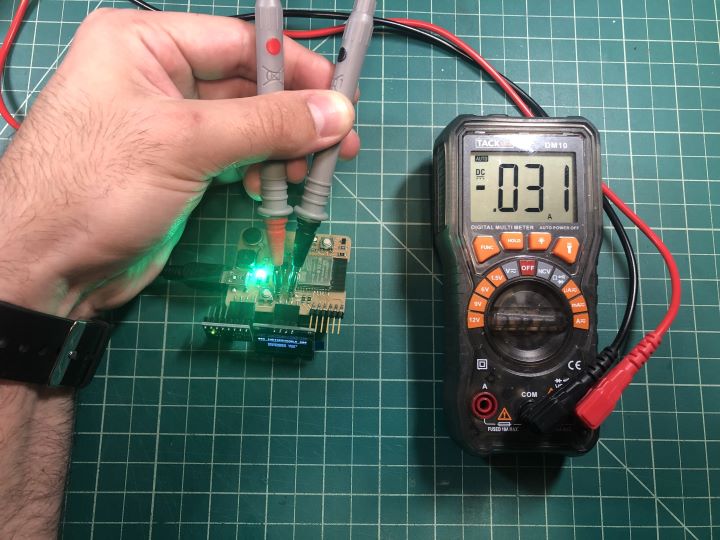
Jun 15
I finally got around to testing the current draw of an output device. I powered up the board with the ESP32 outputting a message to a 128x64 SSD1306 over I2C. I hooked up the two probes of my multimeter to the VCC and GND pins of the SSD1306, and found that 31 mA of current was flowing between them.