Week 10: Input Devices
This week offered a great opportunity to make some headway on the core functionality of my final project.
Apr 7
In the lecture, Neil highlighted a number of components that could function as input devices in a microcontroller circuit, but I was particularly interested in the hall effect sensor and the gyroscope, as they could be useful to my final project. For my application, one potential set of inputs would be that when the user opens the door to the pill case, a magnet in the door slides over a hall effect sensor. Once the device registers that the door has been opened, the device will start taking readings from the gyroscope. In order for the user to remove the pills from the device, they will have to turn the device upside down, which will be registered by the gyroscope, and cause the device to change states. With this combination of input devices in mind, I began to research their details.
The Allegro Microcontrollers A1326 Hall effect sensor was included in our home kit, and I easily found its datasheet on the Allegro website, as well as detailed documentation from a number of Fab Academy students that had worked with the sensor in the past. A HiLetGo GY-521 MPU-6050 breakout board was also included in the Arduino starter set of our home kit. The board houses a MPU-6050 inertial measurement unit, which integrates a 3-axis accelerometer and a 3-axis gyroscope. The datasheet for the chip can be found here.
Apr 8
I began designing the circuit board in Eagle.

The core of the board would be the ATTiny1614. Aside from the Hall effect sensor and the GY-521, I would add an RGB LED to idicate the state of the sensors. I identified the RGB LED in my home kit as the CLV1A-FKB, and referenced its datasheet to find its pinout.

I also referenced the A1326 datasheet to find the Hall effect sensor pinout.

I then referenced this LED resistor calculator to identify the proper resistor values. For LEDs, it’s important to factor in the voltage drop across the LED when determining this value. This was the final piece of the puzzle, and the circuit board design was complete.


Apr 9
I moved all of my SMD resistors and capacitors to a Box-All in order to simplify the process

Milling and stuffing the board went without a hitch.

I also created a modified FTDI-UPDI adapter that featured a LED, rounded corners, and pogo pins.


This pogo pin adapter allowed me to eliminate the UPDI headers from my board so I could make it less pointy.
Apr 10
I took another shot at using the ESP32, and figured out how to modify the footprint of the device so it was compatible with the design rules. In the control panel, you click “File,” “Open,” and “Library,” then select the .lbr file of the desired library.

This will bring you into the library editor environment, where you can choose the device footprint you wish to edit by right clicking, then choosing “Edit.”

This will bring you into the footprint editing environment, where you can select a pad, and adjust the dimensions. This was much simpler than I imagined it would be, as the pads’ positions are defined relative to their “centroid,” rather than one of their corners, so the relative spacing between an array of pads remains consistent.
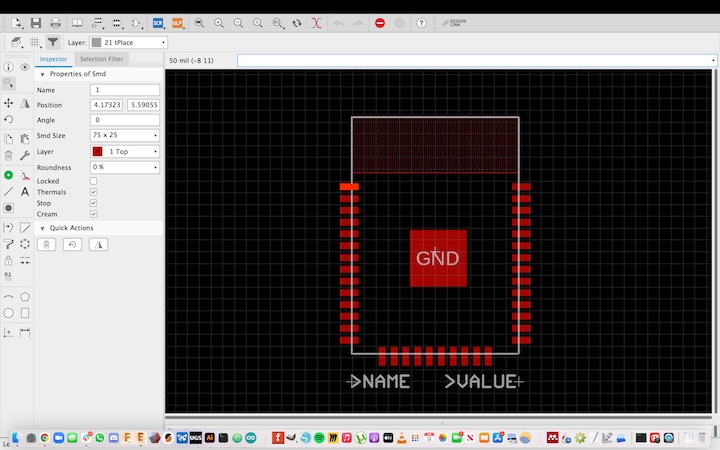
By reducing the size of the pads on the ESP32 footprint, the device passed the “FAB” design rules check, indicating that I will be able to mill it on my 3018 PCB mill!
Apr 11
I adapted code from examples other students had referenced to create a sketch that would cause the state of the LED to change when a magnet was passed over the Hall effect sensor.
int hallEffectPin = 3;
int ledPinRed = 0;
int ledPinGreen = 1;
int state = 0;

void setup() {
  // put your setup code here, to run once:
  pinMode(ledPinRed, OUTPUT);
  pinMode(ledPinGreen, OUTPUT);
  pinMode(hallEffectPin, INPUT_PULLUP);

}

void loop() {
  // put your main code here, to run repeatedly:
  state = digitalRead(hallEffectPin);
  if (state == LOW) {
    digitalWrite(ledPinGreen,LOW);
    digitalWrite(ledPinRed,HIGH);
    delay(100);
    digitalWrite(ledPinGreen,HIGH);
    digitalWrite(ledPinRed,HIGH);
    delay(900);
  }
  else {
    digitalWrite(ledPinRed, LOW);
    digitalWrite(ledPinGreen, HIGH);
    delay(200);
    digitalWrite(ledPinGreen,HIGH);
    digitalWrite(ledPinRed,HIGH);
    delay(200);
  }

}
The sketch worked, but not quite exactly as intended. When the magnet waved over the sensor, the light changed state, and stayed that state until the magnet was flipped back over and waved over the sensor again. For the sake of the pill case, I want the state to flip only when the magnet is over the the sensor, but to return to the original state when the magnet is removed. The magnet will be mounted firmly inside the enclosure, so it must be able to change the state of the sensor without being flipped over.
Apr 29
Greg helped me write a basic sketch to connect the ATTiny1614 to the Arduino IDE serial monitor via the FTDI connector. This was very simple, but demonstrated the ability of the IC to communicate with the computer, which represents a large step forward toward the functionality of my final project.
I added the code to the Arduino IDE, and compiled the sketch to confirm that there were no syntax errors.
int counter = 0;

void setup(){
Serial.begin(115200);
Serial.println(F("Starting serial communication..."));
}

void loop(){
Serial.print(F("Counter = "));
Serial.print(counter);
Serial.println("");
counter++;
delay(1000);
}
I programmed programmed the board using the board’s UPDI pads with the FTDI programmer and the FTDI to UPDI adapter detailed previously. Once programmed, I disconnected the adapter, and connected the FTDI programmer directly to the board.

Importantly, I checked that the TX pin on the FTDI programmer was connected to the RX pin on the board, and vice-versa.

I opened the serial monitor in the Arduino IDE and made sure that the baud rate in the bottom right of the window matched the rate specified in the Serial.begin command (115200, in this case).

The loop in the sketch adds to the counter function every second, and the serial monitor outputs this in a new line in real time.
May 8
I was finally able to get the Miniware DS212 Oscilloscope working, and got some readings from the LED.