Week 8: Embedded Programming
This week will be an important one to get me moving in the right direction toward my final project goals. I plan on utilizing the ESP32 as the brains of my project, so I’ll be focusing some time this week to get a better idea of how it works and how to program it.
Mar 17
Parts of this week’s lecture were helpful, but other sections were a bit over my head. It was interesting to learn about the different architectures that microcontrollers have, but I’m still not totally sure about what these architectures mean on a functional level. Neil mentioned that the ESP32 uses the XTENSA architecture, so I have a starting place to begin my research. I learned that XTENSA is an instruction set developed by Tensilica, and that the ESP32 is a series of system-on-a-chip modules developed by Espressif. On the Espressif website, I found the ESP32 Datasheet, Hardware Design Guidelines, and Technical Documents. I also learned about ESP Rainmaker which incorporates a SDK, “self-adapting” phone apps, and cloud hosting services through AWS.
Reading through the datasheet, I learned a number of things about the ESP32. First, the board is powered by 3.3V, so I’ll need to use a voltage regulator to step down from the 5V put out over USB. Next, TX and RX are GPIO1 and GPIO3 respectively, so I can program the board over FTDI. Additionally, the board can support two separate I2C busses. The default SDA and SCL pins are GPIO21 and GPIO22 respectively, but other pins can be configured in code to serve these functions. A couple of other cool things I learned about the ESP32 are that the chip has ten capacitive touch sensor pins that can detect electrical changes in anything that holds a charge, and that it has an integrated Hall effect sensor under the metal covering.
Mar 18
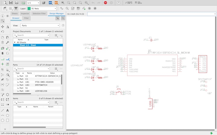
The local node lecture was a good overview of basic C coding and the Arduino IDE. We covered basic structure and syntax, wrote a sketch to control a blinking LED with a sketch, and detailed the process of uploading it to an AVR board using an FTDI programmer with a UPDI adapter. I discussed how I could use this week’s assignment to advance my final project with Greg, and he recommended that I continue development with the ATTiny boards, rather than attempting to program the ESP32 at this stage. Taking this advice, I decided to design a board around the ATTiny1614, and incorporate a number of LEDs and a button, with the goal being to create a test bench for for the light sequences that would appear on the pill case when a medication reminder is triggered.
Mar 19
In order to prepare for milling the circuit board, I milled the surface of my router’s waste board to flatten it with a Speed Tiger 1/8” four-flute square end mill. In order to do this, I generated a file in Illustrator with a black box the size of the area I wanted to be milled, surrounded by a thin white perimeter.

I imported this into Mods, and treated the file as a milling operation, increasing the number of offsets until the entire black square was filled with milling tool paths. The milling operation was successful, and my wast board was prepared for PCB milling.
Mar 20
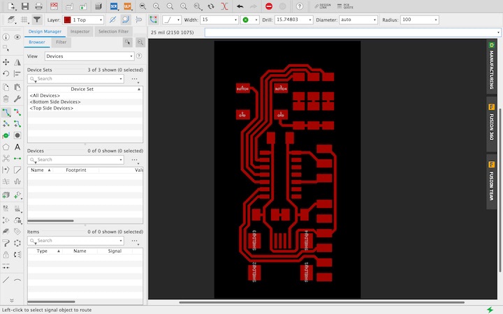
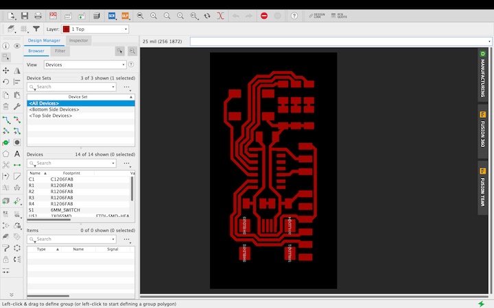
I began to design the PCB in Eagle. It was not very different than the process of designing the ATTiny412 board, and I followed the same steps to import the ATTiny1614 files into the “Fab” Eagle library. The routing process was a bit more difficult as I had more traces to route, but I find the process rather enjoyable. The first version of the board had 15 mil trace width.
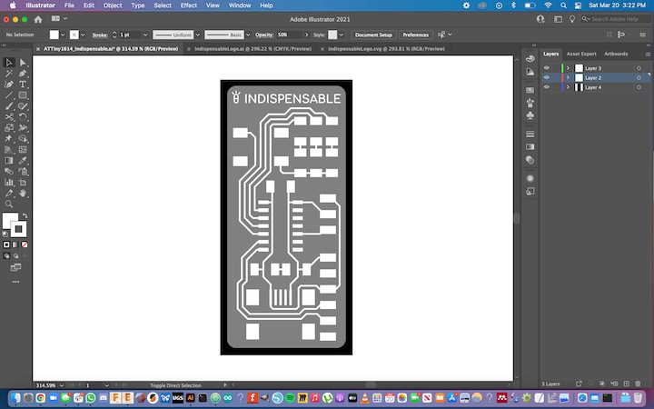
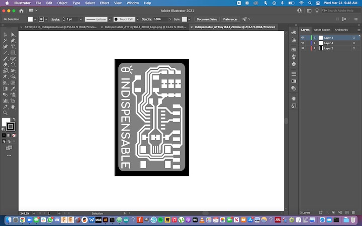
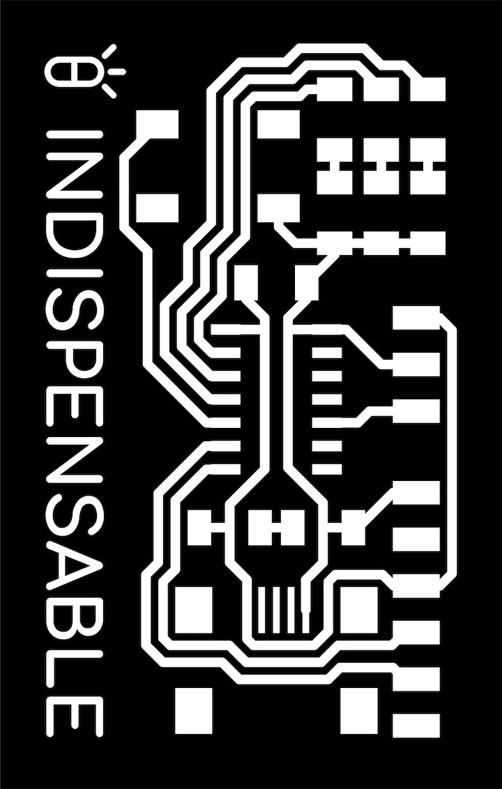
Rather than exporting the top layer as a .png file and creating the perimeter of the board in GIMP, I exported the layer as a .dxf file, and imported it into Illustrator. From there, I had finer control over the alignment of the traces within the perimeter, and I could adjust the perimeter much more easily once it had been created. More importantly, I could also add vector graphics, such as the Indispensable logo, to the board as part of the traces layer.
Once I was happy with the results, I exported the traces and perimeter as monochrome .png files. I processed the files in Mods as before, but when I uploaded them into UGS, I noticed there were some odd tool paths.
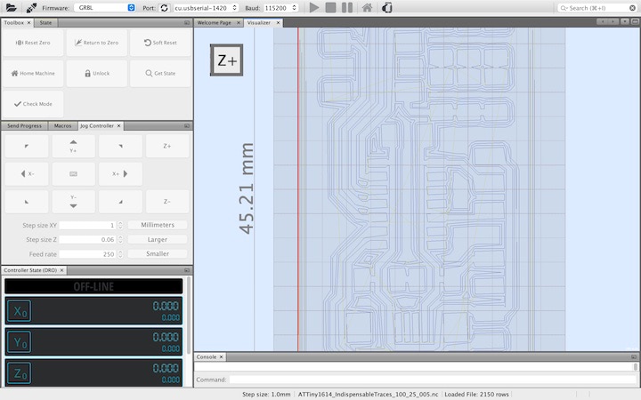
After some experimentation, I discovered that these crooked tool paths were due to low resolution, as when I exported the files at 2400 dpi, the tool paths looked perfect. I milled the board with with the PreciseBits 0.0150” Tapered-stub end-mill. I followed Daniel’s documentation to determine the appropriate speeds and feeds for the bit. While theses calculations suggest that I should be milling at over 800 mm / min, my CNC mill isn’t very rigid, so I ran some small scale tests, starting at 200 mm / min, working up to 400 mm / min. Comparing the results, I decided to mill the traces at 250 mm / min. I was very impressed with how quickly this bit can mill on such a cheap machine.
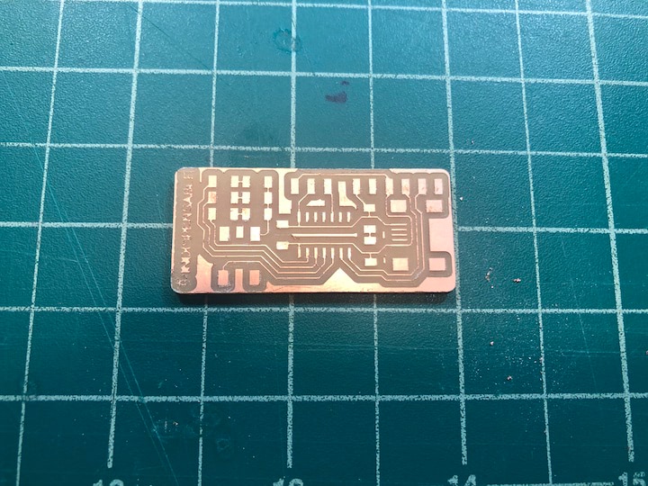
While the traces of the board all looked fine, the logo was slightly too small, and was essentially unreadable. Unfortunately, shortly after taking this picture, some of the traces were damages when attempting to clean up some of the leftover copper along the outside of the board, so I cried and went to bed.
Mar 21
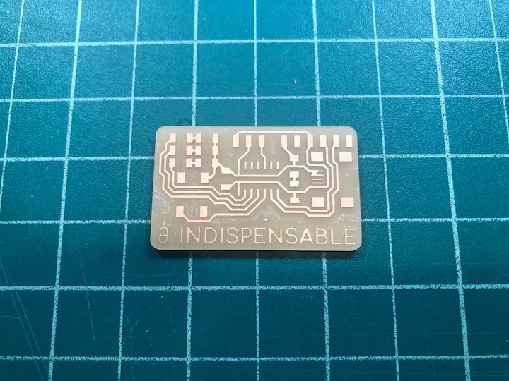
Wiping away my tears, I decided to widen my traces to 20 mil and reorient the logo so it could be larger. This process wasn’t very difficult, and it went rather quickly.

The milling process went very smoothly. The traces looked much more durable, and the logo was much more visible. One thing that I realized at this stage was that as the tapered-stub end mills are tapered, I will need to account for the fact that as the depth of cut increases, the cutting path will be wider at the surface of the PCB. It will be relatively easy to compensate for this in Mods, as the bit has a known taper angle of 15 degrees.
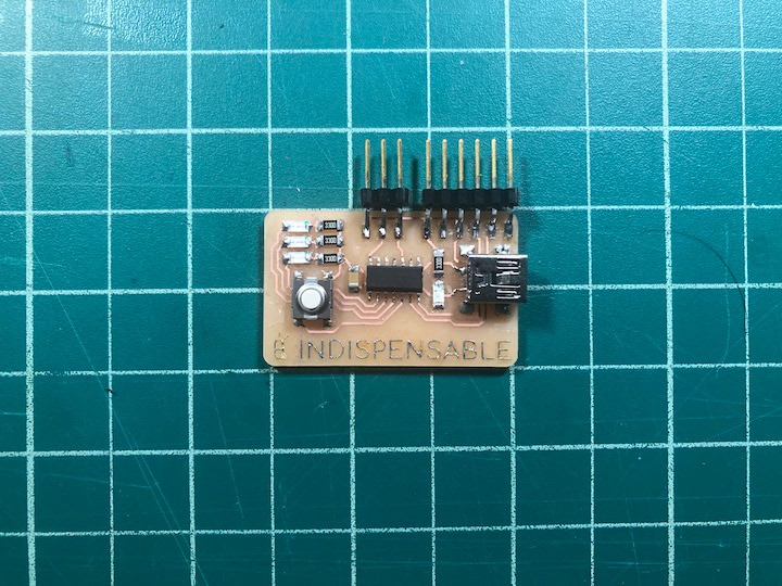
The soldering process also went very smoothly. The one thing that is slightly difficult is holding the header pins in place while attempting solder them. For my next board, I hope to make these headers obsolete by using a programmer with pogo pins.
Mar 23
I uploaded the sketch at the bottom of this page to the board, which displays a green light when the board turns on, then repeats a long, flashing light pattern once the button is pressed.
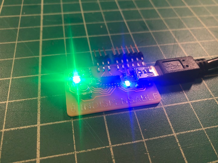
While it was definitely exciting to get as far as I did, the sketch doesn’t quite meet the requirements for use in my final project. If this board were to be embedded in the pill case, you could imagine that there would be some base-level indication of connectivity until the medication reminder was triggered, at which point the light would change to indicate that it’s time to take your pills. At this point, the sequence I created would begin, gradually changing from a friendly reminder to an urgent alarm as time goes on. The key difference is that in the pill case, when the user opens the device to access the pills, the button would be pressed and the sequence would stop. With the current sketch, once the button is pressed, the alarm sequence repeats infinitely. Luckily, the hardware works exactly as intended, serving as a test bed for future iterations of these sketches, so I can refine this sub-system of the pill case before creating more elaborate boards.
One clear next step will be to move away from using delays in my code, as button presses cannot be registered during delays. I did find a tutorial on the Arduino website, explaining how to use the BlinkWithoutDelay example sketch to allow the microcontroller to multitask.
Code
//
// ATTiny1614_Indispensable.ino
//
// INDISPENSABLE PILL CASE v0.1
//
// Griffin van Horne - 3/22/21
//
// This work may be reproduced, modified, distributed,
// performed, and displayed for any purpose, but must
// acknowledge this project. Copyright is retained and
// must be preserved. The work is provided as is; no
// warranty is provided, and users accept all liability.
//

#define LED_Green 0
#define LED_Yellow 1
#define LED_Red 2
#define button 3
const int debounce = 200;
int buttonState = HIGH;
_Bool LEDstate = false;

void setup() {
   pinMode(LED_Green,OUTPUT);
   pinMode(LED_Yellow,OUTPUT);
   pinMode(LED_Red,OUTPUT);
   pinMode(button,INPUT_PULLUP);

}

void loop() {

//BUTTON
buttonState = digitalRead(button);

  if (buttonState == LOW){
    if(LEDstate == true){
      LEDstate = false;
    }
    else{
      LEDstate = true;
    }
    delay(debounce);
  }

  displayLED_Green();

}

void displayLED_Green() {
  if(LEDstate == true){
   digitalWrite(LED_Green,LOW);
   digitalWrite(LED_Yellow,LOW);
   digitalWrite(LED_Red,LOW);
   delay(200);
   digitalWrite(LED_Green,HIGH);
   digitalWrite(LED_Yellow,LOW);
   digitalWrite(LED_Red,LOW);
   delay(200);
   digitalWrite(LED_Green,LOW);
   digitalWrite(LED_Yellow,LOW);
   digitalWrite(LED_Red,LOW);
   delay(200);
   digitalWrite(LED_Green,HIGH);
   digitalWrite(LED_Yellow,LOW);
   digitalWrite(LED_Red,LOW);
   delay(200);
   digitalWrite(LED_Green,LOW);
   digitalWrite(LED_Yellow,LOW);
   digitalWrite(LED_Red,LOW);
   delay(200);
   digitalWrite(LED_Green,HIGH);
   digitalWrite(LED_Yellow,LOW);
   digitalWrite(LED_Red,LOW);
   delay(200);
   digitalWrite(LED_Green,LOW);
   digitalWrite(LED_Yellow,LOW);
   digitalWrite(LED_Red,LOW);
   delay(200);

// YELLOW LIGHT SEQUENCE
   digitalWrite(LED_Green,LOW);
   digitalWrite(LED_Yellow,HIGH);
   digitalWrite(LED_Red,LOW);
   delay(3000);
   digitalWrite(LED_Green,LOW);
   digitalWrite(LED_Yellow,LOW);
   digitalWrite(LED_Red,LOW);
   delay(200);
   digitalWrite(LED_Green,LOW);
   digitalWrite(LED_Yellow,HIGH);
   digitalWrite(LED_Red,LOW);
   delay(200);
   digitalWrite(LED_Green,LOW);
   digitalWrite(LED_Yellow,LOW);
   digitalWrite(LED_Red,LOW);
   delay(200);
   digitalWrite(LED_Green,LOW);
   digitalWrite(LED_Yellow,HIGH);
   digitalWrite(LED_Red,LOW);
   delay(200);
   digitalWrite(LED_Green,LOW);
   digitalWrite(LED_Yellow,LOW);
   digitalWrite(LED_Red,LOW);
   delay(200);
   digitalWrite(LED_Green,LOW);
   digitalWrite(LED_Yellow,HIGH);
   digitalWrite(LED_Red,LOW);
   delay(200);
   digitalWrite(LED_Green,LOW);
   digitalWrite(LED_Yellow,LOW);
   digitalWrite(LED_Red,LOW);
   delay(200);

// RED LIGHT SEQUENCE
   digitalWrite(LED_Green,LOW);
   digitalWrite(LED_Yellow,LOW);
   digitalWrite(LED_Red,HIGH);
   delay(3000);
   digitalWrite(LED_Green,LOW);
   digitalWrite(LED_Yellow,LOW);
   digitalWrite(LED_Red,LOW);
   delay(200);
   digitalWrite(LED_Green,LOW);
   digitalWrite(LED_Yellow,LOW);
   digitalWrite(LED_Red,HIGH);
   delay(200);
   digitalWrite(LED_Green,LOW);
   digitalWrite(LED_Yellow,LOW);
   digitalWrite(LED_Red,LOW);
   delay(200);
   digitalWrite(LED_Green,LOW);
   digitalWrite(LED_Yellow,LOW);
   digitalWrite(LED_Red,HIGH);
   delay(200);
   digitalWrite(LED_Green,LOW);
   digitalWrite(LED_Yellow,LOW);
   digitalWrite(LED_Red,LOW);
   delay(200);
   digitalWrite(LED_Green,LOW);
   digitalWrite(LED_Yellow,LOW);
   digitalWrite(LED_Red,HIGH);
   delay(200);
   digitalWrite(LED_Green,LOW);
   digitalWrite(LED_Yellow,LOW);
   digitalWrite(LED_Red,LOW);
   delay(200);

// PARTY MODE
   digitalWrite(LED_Green,HIGH);
   digitalWrite(LED_Yellow,LOW);
   digitalWrite(LED_Red,LOW);
   delay(200);
   digitalWrite(LED_Green,LOW);
   digitalWrite(LED_Yellow,HIGH);
   digitalWrite(LED_Red,LOW);
   delay(200);
   digitalWrite(LED_Green,LOW);
   digitalWrite(LED_Yellow,LOW);
   digitalWrite(LED_Red,HIGH);
   delay(200);
   digitalWrite(LED_Green,LOW);
   digitalWrite(LED_Yellow,LOW);
   digitalWrite(LED_Red,LOW);
   delay(200);

// FLASH SEQUENCE
   digitalWrite(LED_Green,HIGH);
   digitalWrite(LED_Yellow,HIGH);
   digitalWrite(LED_Red,HIGH);
   delay(200);
   digitalWrite(LED_Green,LOW);
   digitalWrite(LED_Yellow,LOW);
   digitalWrite(LED_Red,LOW);
   delay(200);
   digitalWrite(LED_Green,HIGH);
   digitalWrite(LED_Yellow,HIGH);
   digitalWrite(LED_Red,HIGH);
   delay(200);
   digitalWrite(LED_Green,LOW);
   digitalWrite(LED_Yellow,LOW);
   digitalWrite(LED_Red,LOW);
   delay(200);
   digitalWrite(LED_Green,HIGH);
   digitalWrite(LED_Yellow,HIGH);
   digitalWrite(LED_Red,HIGH);
   delay(200);
   digitalWrite(LED_Green,LOW);
   digitalWrite(LED_Yellow,LOW);
   digitalWrite(LED_Red,LOW);

// PAUSE
   delay(3000);
   }

  else{
    digitalWrite(LED_Green, HIGH);
    digitalWrite(LED_Yellow, LOW);
    digitalWrite(LED_Red, LOW);
  }

}