Assignments
1. Principles and practices
2. Project management
3. Computer Aided design
4. Computer controlled cutting
5. Electronics production
6. 3D Scanning and printing
7. Electronics design
8. Computer controlled machining
9. Embedded programming
10. Mechanical Design
11. Input devices
12. Molding and Casting
13. Output devices
14. Networking and communications
15. Interface and application programming
16. Wildcard week
17. Applications and implications
18. Invention, intellectual property and income
19. Project development
7. Electronics Design
Assignment:Group assignment:
Use the test equipment in your lab to observe the operation of a microcontroller circuit board (in minimum, check operating voltage on the board with multimeter or voltmeter and use oscilloscope to check noise of operating voltage and interpret a data signal) Document your work (in a group or individually)
Individual assignment:
Redraw one of the echo hello-world boards or something equivalent, add (at least) a button and LED (with current-limiting resistor) or equivalent input and output, check the design rules, make it, test it.
Group Assignment
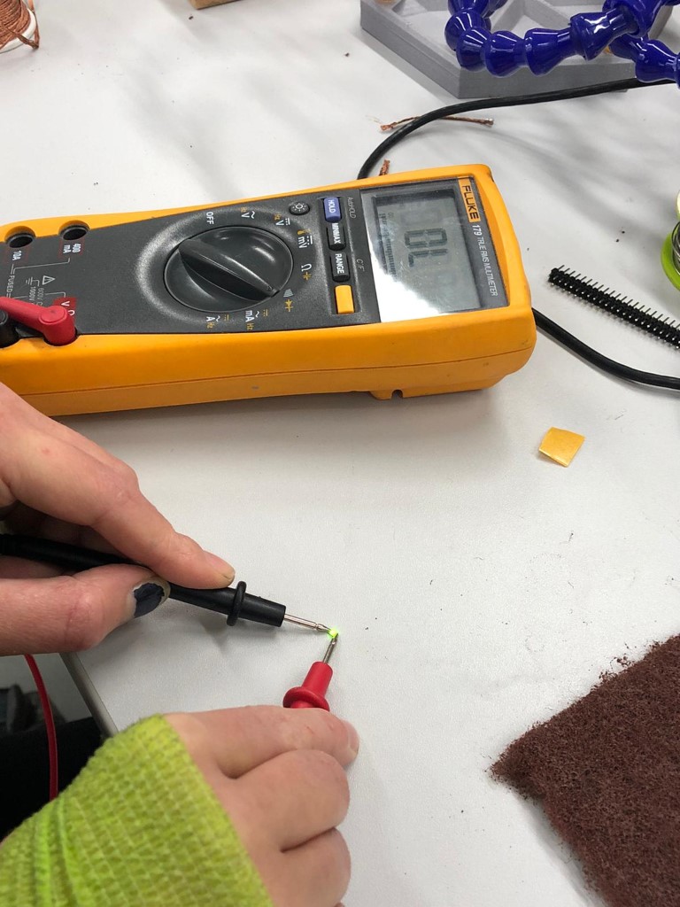
The main tool we use to test our boards is a multimeter.
With this we can messaure the resistance, check if connections are right and or if there are faulty soldering bridges. We can also check the directions of our components and the strength of a resistor. Here I'm checking if the LED works and which way I have to build it in by using a multimeter.
The testing of the operation of a microcontroller using a multimeter and a oscilloscope ist linked on the page of our group member Lars Mattern. You can find the documentation here.
Planning

So as you can see in this sketch, I'd like the main board to be center of the attention. It should be part of the tree. Since it should be able to control the led matrix in the back, the conductive field on the front and little hidden motors etc. To make this possible, I chose to rebuild an arduino, with the addition of an LED and a button.
Parts:
| Parts | Type | Value | Eagle keywoards |
| ATmega328p | TQFP | - | ATmega328P-AU |
| Crystal | - | 16MHZ | Q1 |
| Resistor | 1206 | 1 KΩ | R1K, R1k(2) |
| LED | 1206 | - | LEDRAD |
| Capacitor | C | 100nF | C100NF, C100nf1 |
| Capacitor | C | 15pF | C15oF(1), C15pF(2) |
| Button | - | - | 434123025816 |
Design
The schematic was designed as before in Week 5. I just rebuilt an arduino with the help of my instructor Lena. Here you can find a nice tutorial. And here is one of the many circuit plans of the arduino which you can find on the internet:
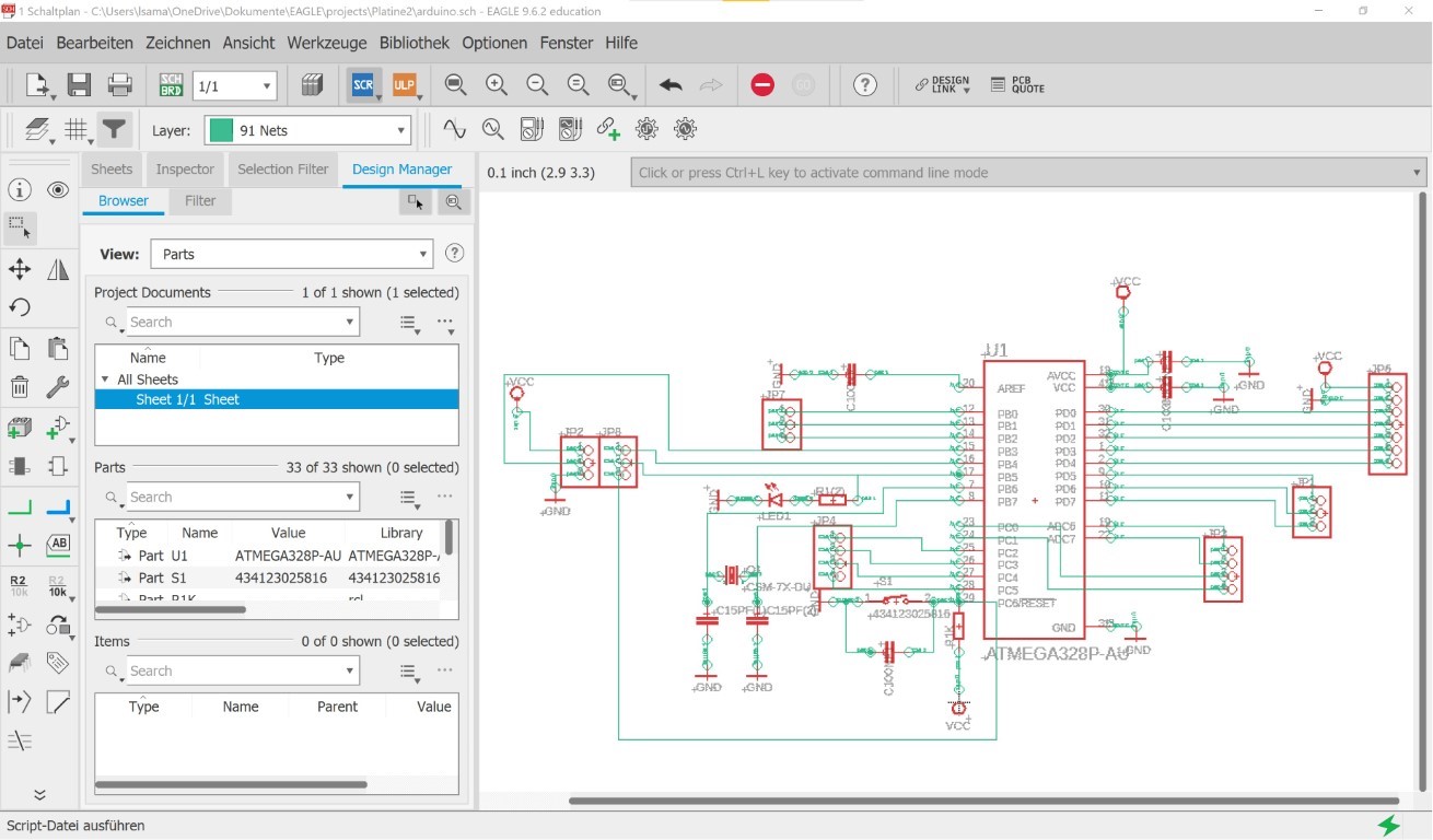
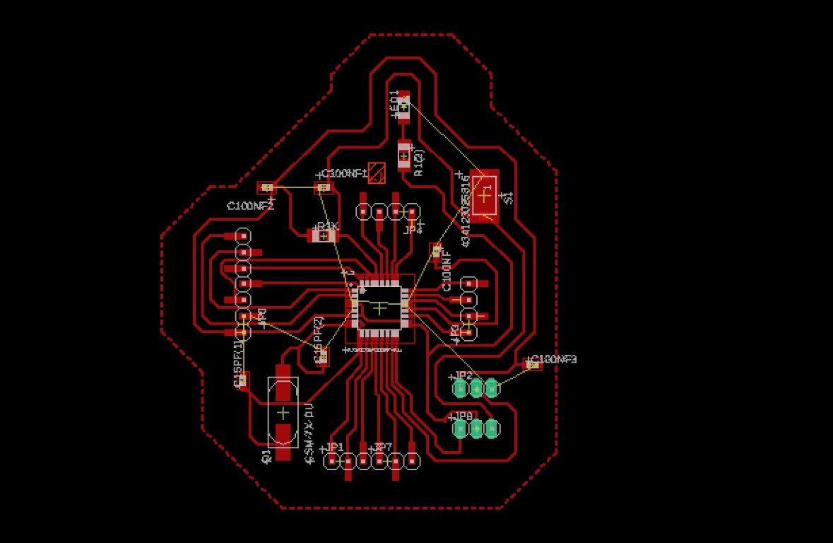
This is how it looks designed in Eagle (additionally a LED and a button). I used two 3x1 pinheads because with one 3x2 pinhead the design was too complex.
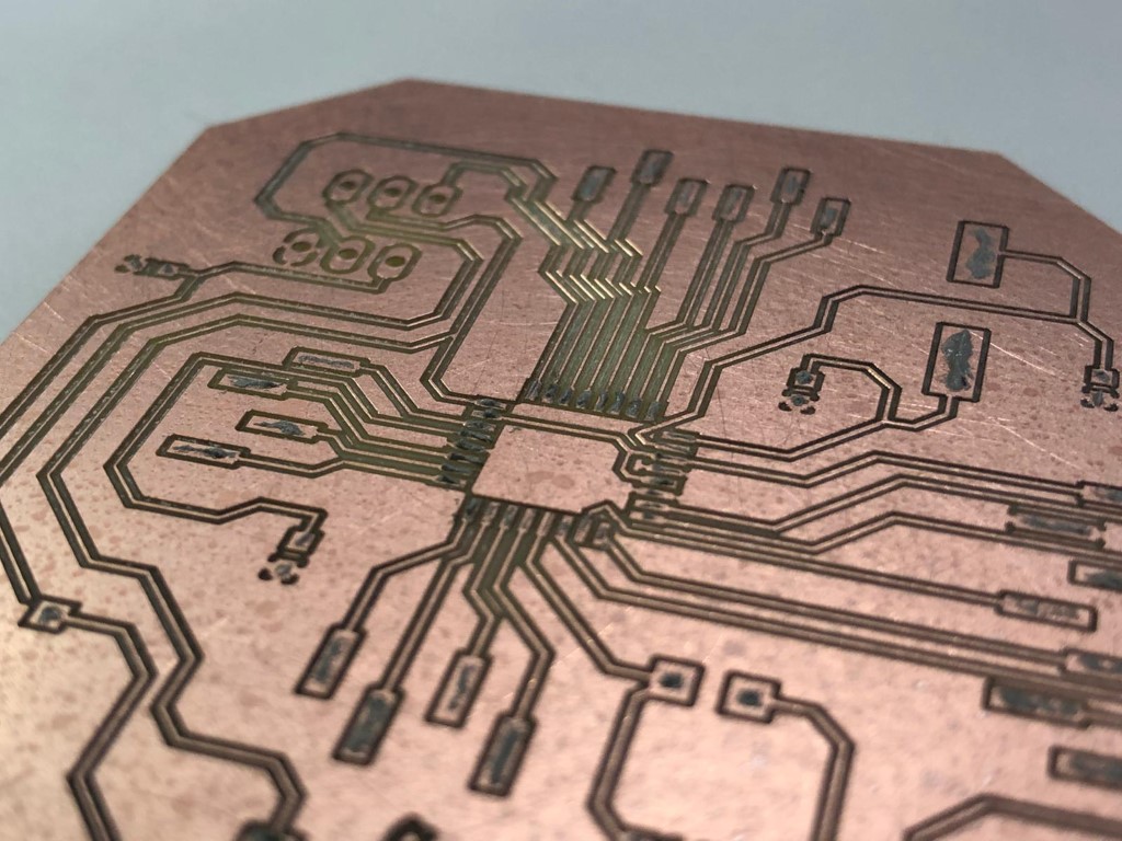
This is the finished design:
Milling Process
To be able to mill, I have to export it first by clicking on the symbol next to the factory symbol on the left. Click on "process job" and you'll see that a new folder was made with some data..jpg)
Now I turn on the machine BEFORE I open the software LPKF CircuitPro. I make a new file and import only the files which have big letters as suffix.
.jpg)
Then I have to go to the "machine overview" tab which is located above the view and click on the circuit board production wizard (the icon with the magic wand). Now I just follow what it says.
.jpg)
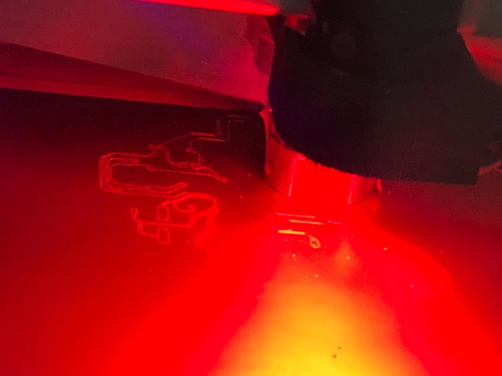
The process is the same as in Week 5. This time the milling took longer since the board had a more complicated design.
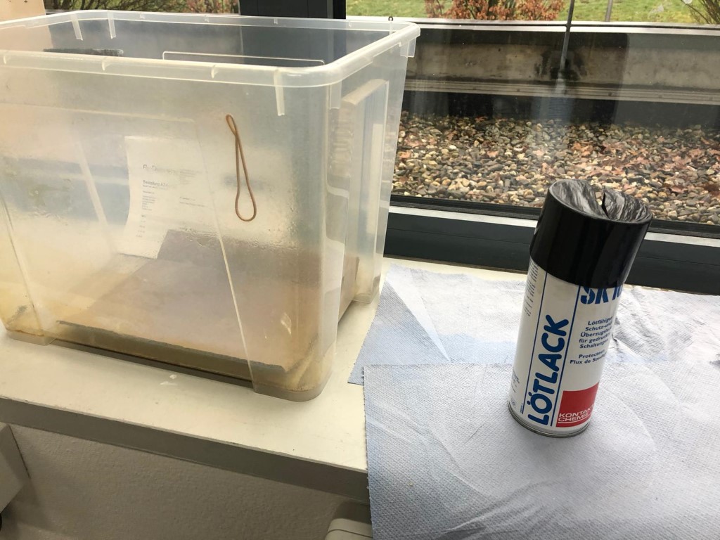
After milling, the pcb is getting placed in the box and sprayed with a soldering vanish to prepare it for soldering. After that it gets rubbed with a cloth to get rid of dirt.
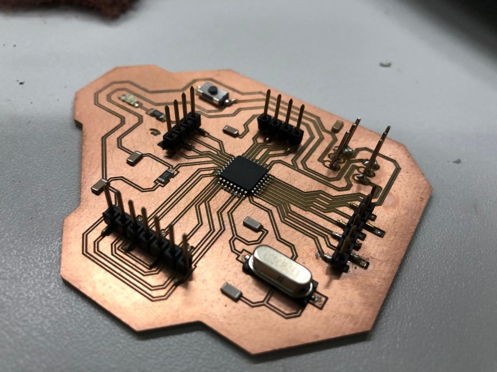
The board is ready for soldering! Each part is getting tested (as seen in the group assignment) and placed. The process is also described in Week 5.
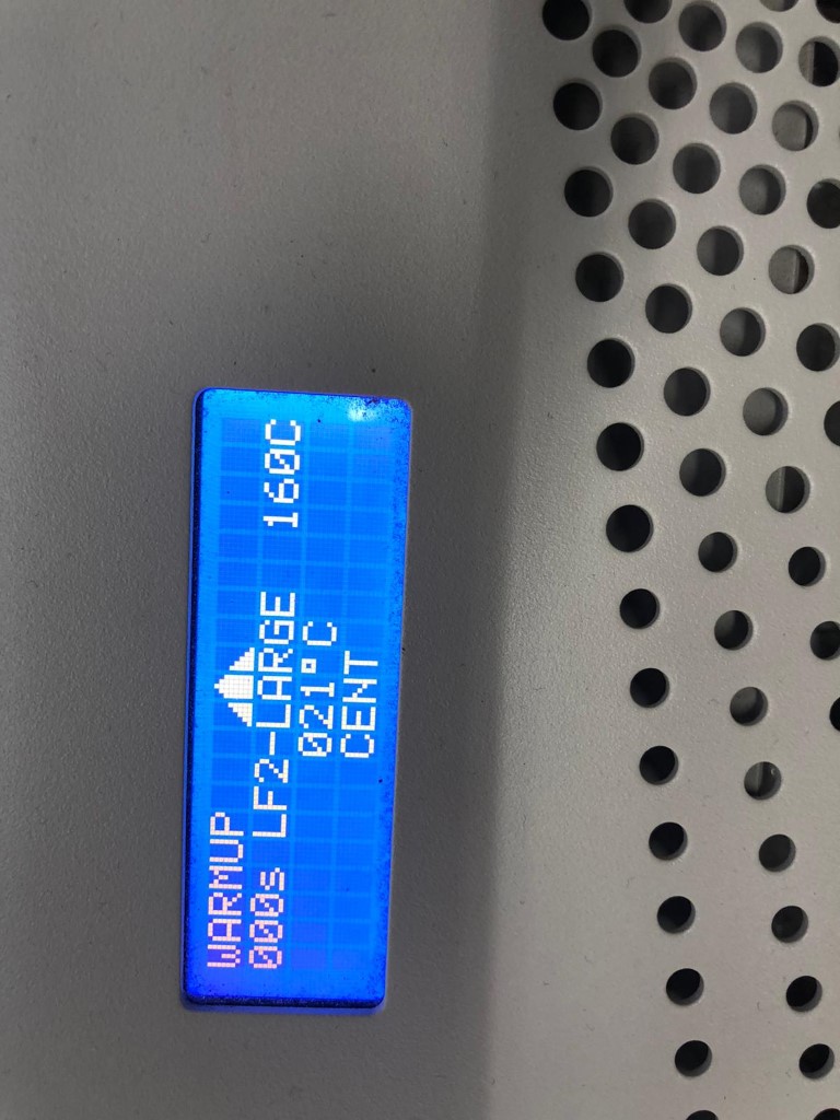
Now it goes into the oven. Here you can see my settings.
Now only the parts which I have to place by hand have to be soldered. My instructor Tobi explained to me how to place pinheads that go through the board: First, you have to push the long side through (as you can see in the pic). Then you lay it on a flat surface so that there is a bit of space between the black plastic and the board. Now we can solder the bottom to the board and pull the plastic off.
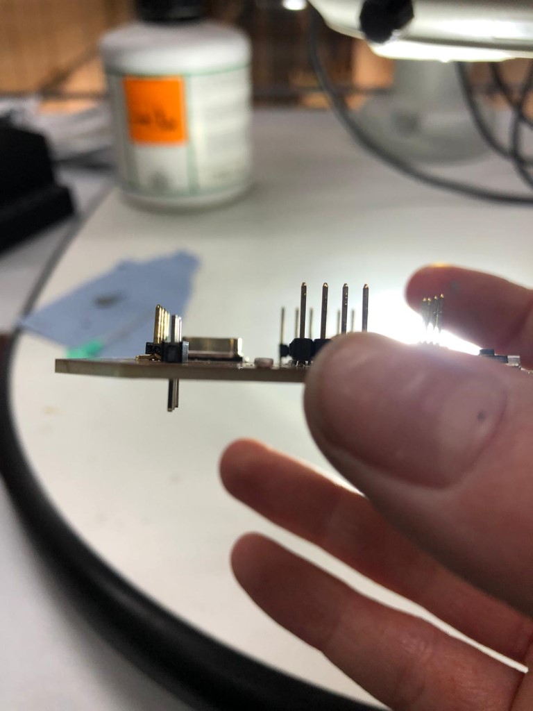
It worked!
Programming
To program I used this Tutorial first. I needed the Arduino software on my ATmega328p first to be able to program it like an arduino.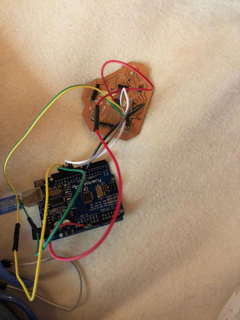
This is how it looked all plugged in! Sadly my board didn't work due to a short. How did I find it out? If I connect ground and vcc to the arduino (ISP), the lights of the arduino turn off. Outchie. Do now I have to check my board under the microscope with a multimeter.
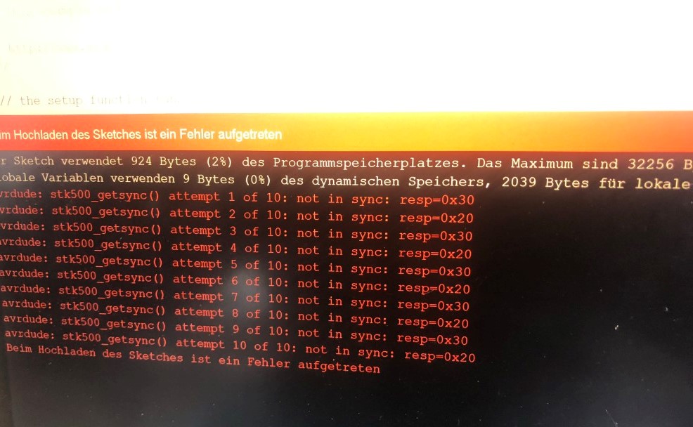
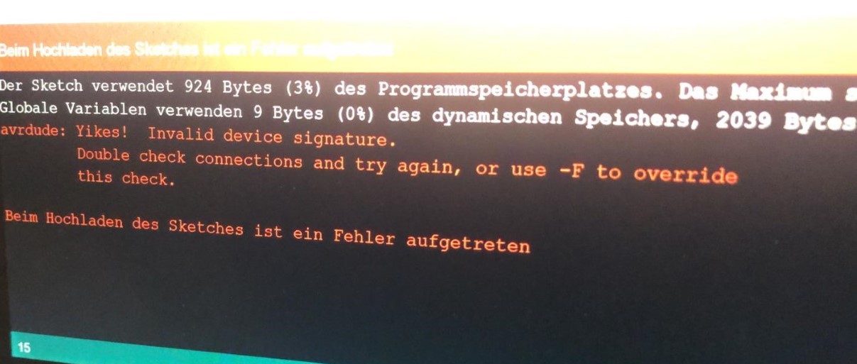
So I was able to fix this. My vcc and gnd were somehow connected (the pin moved slightly during baking) but after that the board seemed to work. Bootloading seemed to work but when I tried to program it with a usb to ttl converter (using the blink- example from arduino), I first got this error:
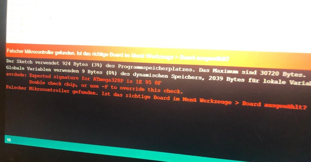
I pressed the reset button wildly and got this error:
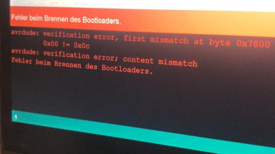
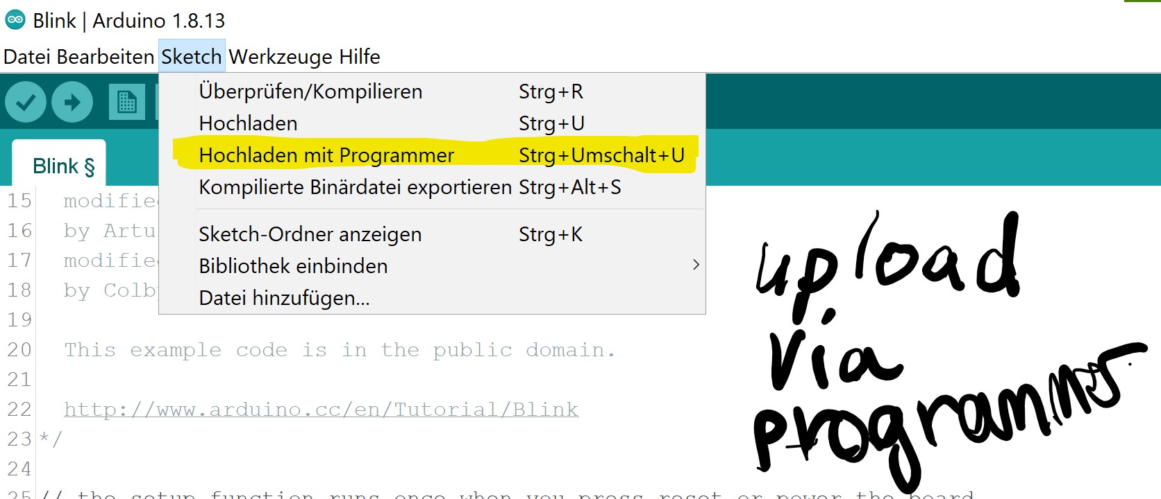
Then I tried to program it using an arduino like this: I went to sketch> upload using programmer and got those errors:
What I've done:
- tested the reset button (works)
- 5v is connected to vcc
- gnd to gnd
- rxd to txd
- txd to rxd
- the Pins are properly connected to the atmega328p —> i checked that with a multimeter with the help of my instructor
- my pc recognizes the usb to serial connector
- I used the same board settings as when I burned it
- my programmer is Avrisp mkii (after that I tried every listed programmer)
What I've also tried:
- I tried bootloading on other PCs and with other cables and other arduinos
- I’ve chosen the right com (since I only have one)
- the reset button seemed to work since it won’t do anything when I don’t press it (it’s also connected to the reset pin of the atmega)
- I checked together with 2 instructors and a multimeter and there was actually a connection between gnd and vcc before, but I solved it (before the board wasn’t doing anything)
- I also tried every arduino in the avr list to bootload it (first all 328, then all)
- I deinstalled and reinstalled the ide and it’s folders
Since nobody could help me (I asked a ton of people) I decided to deep dive into google, I was determined to find the problem. And after that I was convinced that my chip is broken, either it was already broken or I fried it with the short. However all my errors seem to connect to a not working crystal within the chip itself- feel free to correct me if I'm wrong. I'll make a new board which I'll use in Week 9.
So I remade the whole board and it finally was able to be bootloaded. I threw my Arduino as ISP idea away and bought an USBasp (USB programmer) to be able to do everything quicker.
Here you can see how I connected it:
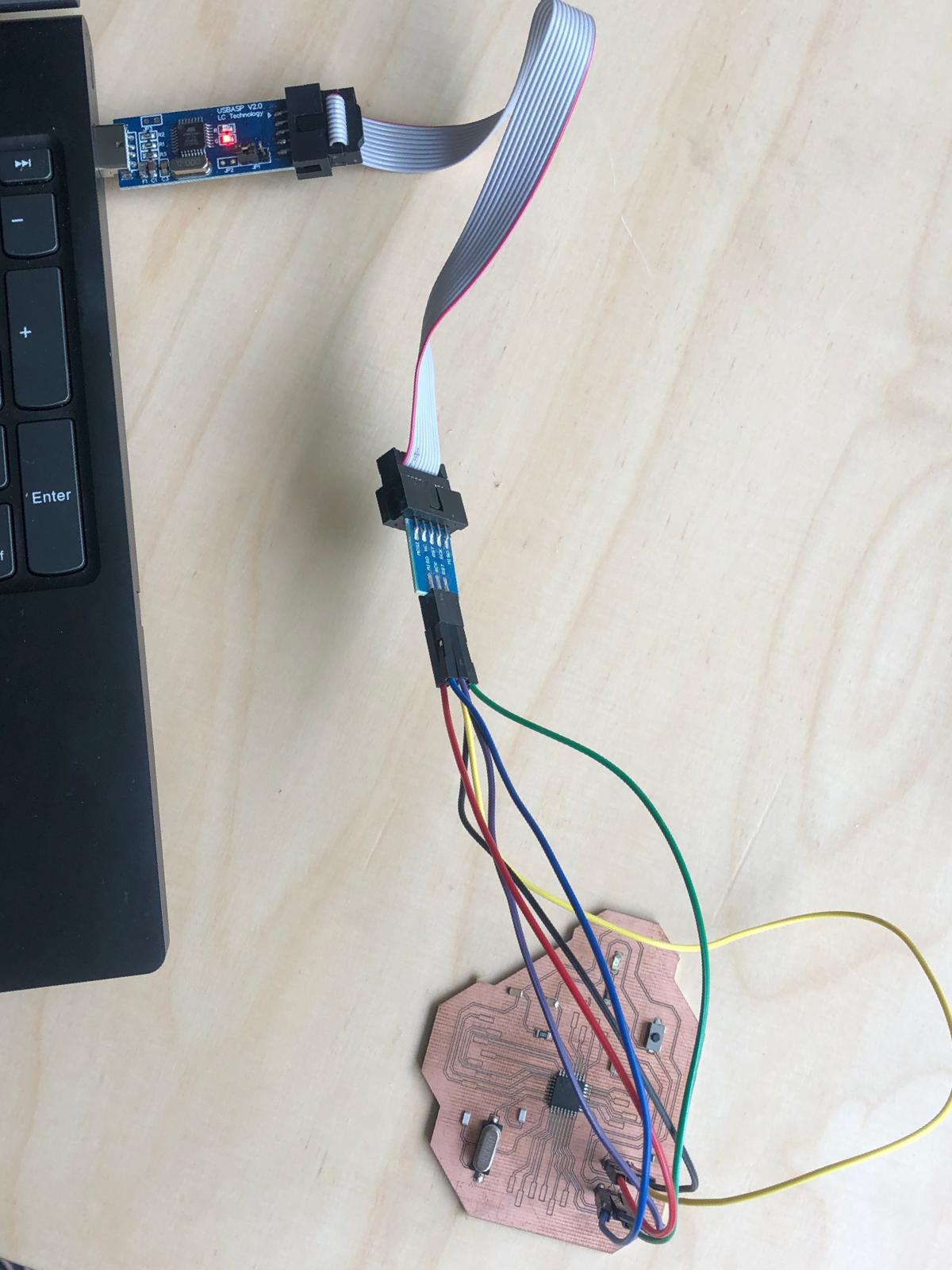
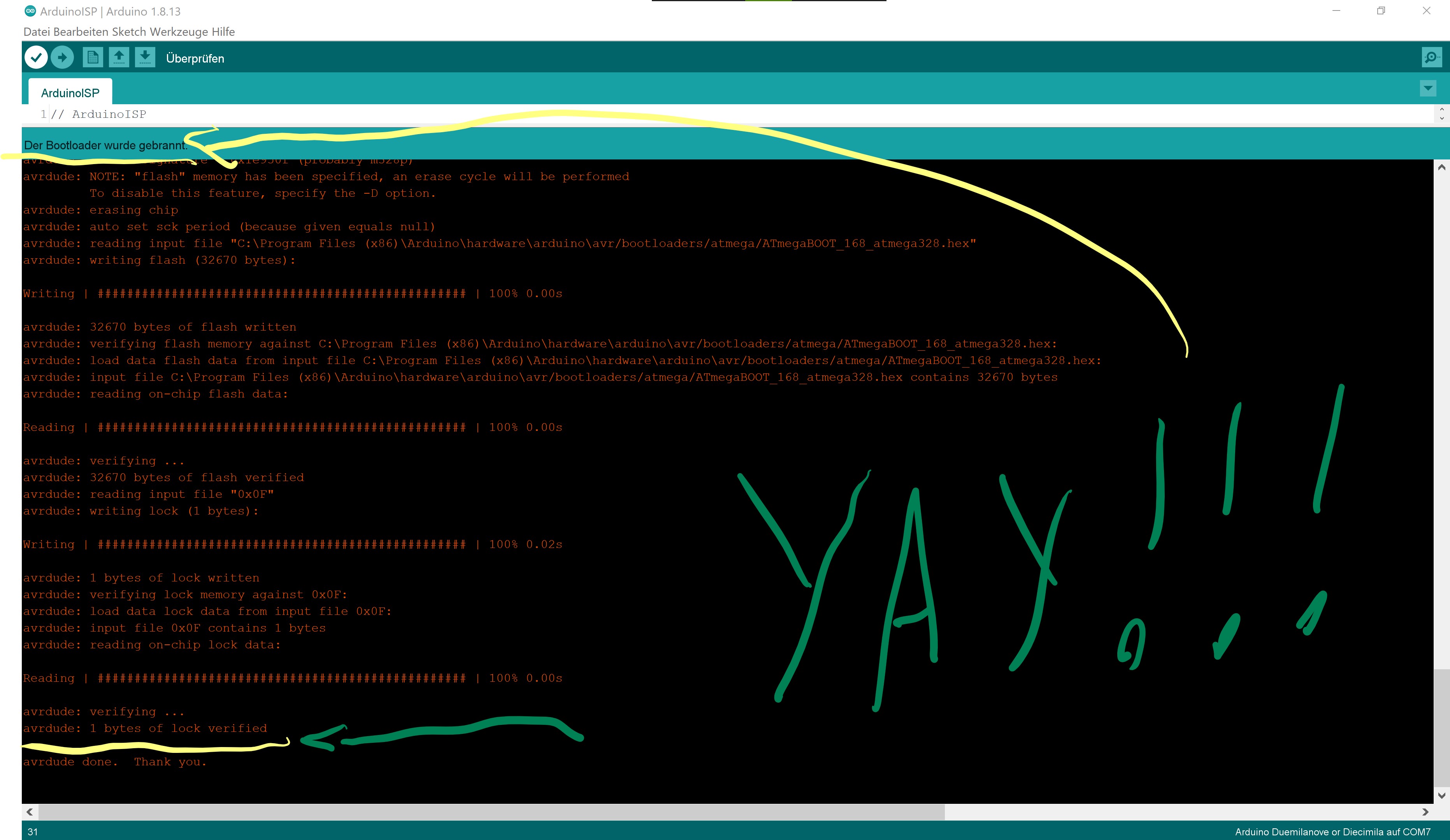
It's nice that on the USB programmer is labeled, that made everything easier. Here are my bootloading specs:
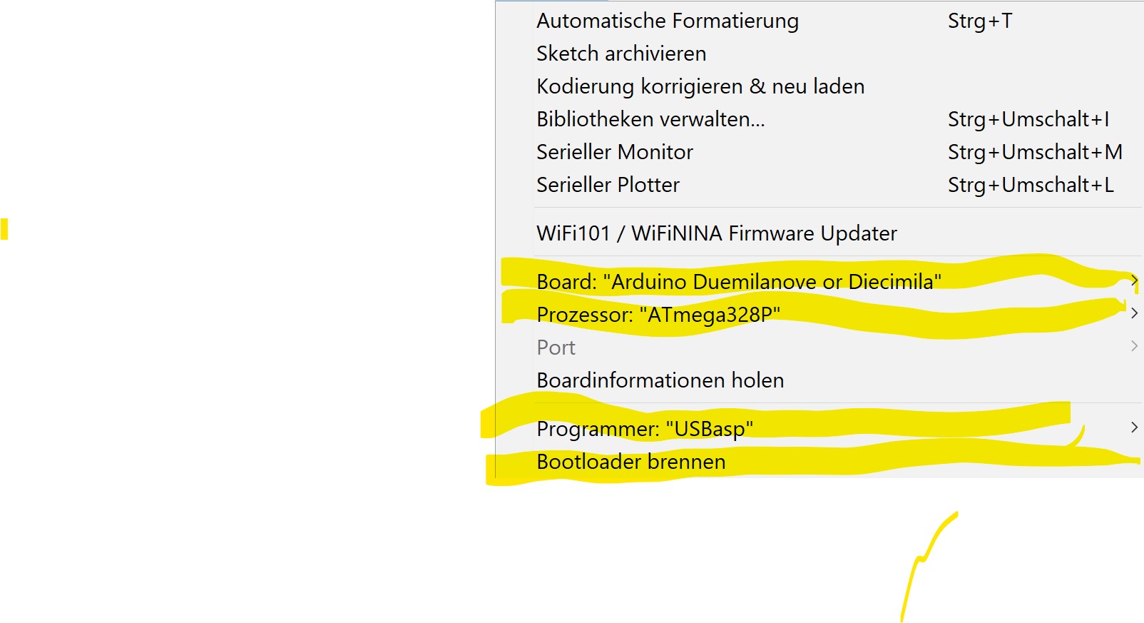
And here you can see that it worked!!
To program it, I just left the programmer plugged in. Then I loaded the blink example from Arduino which you can find on File>Examples>basic>blink.
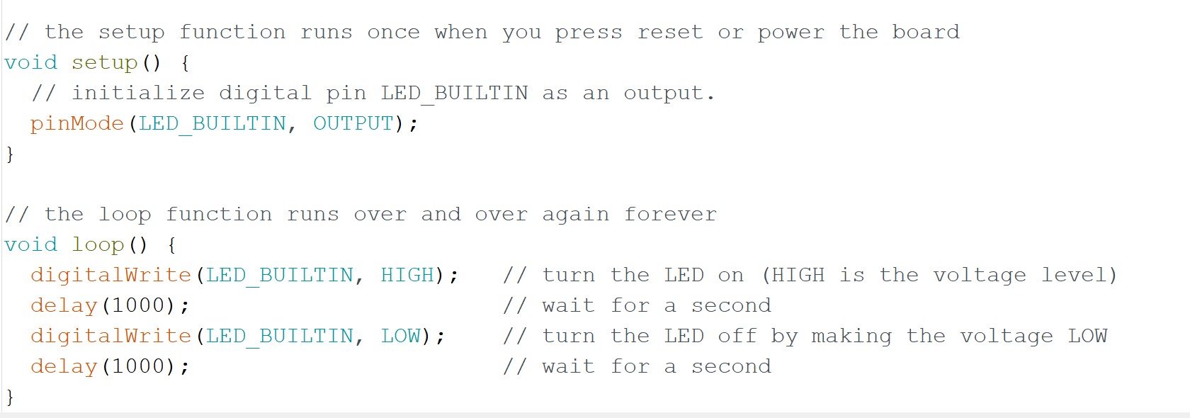
This is how it is looking. When I load it onto the board, the LED should blink in a second algorithm. Then you just upload via programmer.
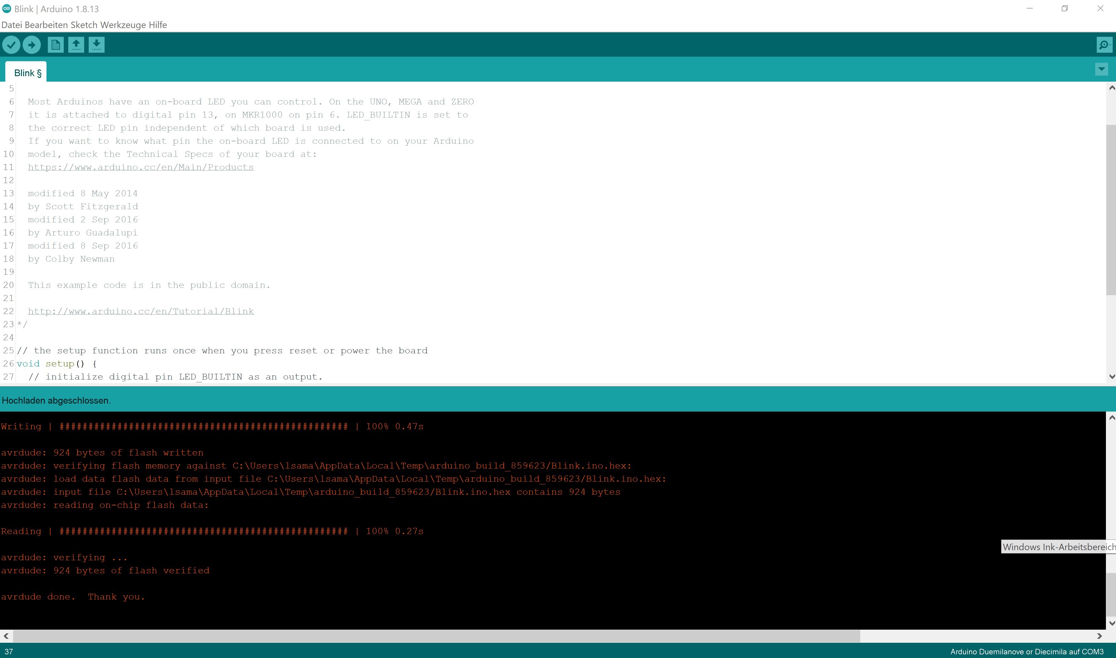
Voila! It's done.
Testing
Let's see if it changes once I change the code to half a second like this.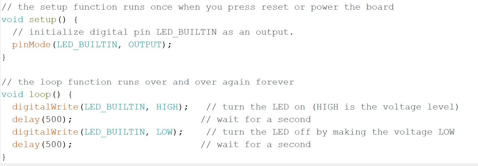
Nice, the board is working fine! Here you can see slow vs. fast: