Assignments
1. Principles and practices
2. Project management
3. Computer Aided design
4. Computer controlled cutting
5. Electronics production
6. 3D Scanning and printing
7. Electronics design
8. Computer controlled machining
9. Embedded programming
10. Mechanical Design
11. Input devices
12. Molding and Casting
13. Output devices
14. Networking and communications
15. Interface and application programming
16. Wildcard week
17. Applications and implications
18. Invention, intellectual property and income
19. Project development
11. Input devices
Assignment:Group assignment:
Probe an input device(s)'s analog and digital signals Document your work (in a group or individually)
Individual assignment:
Measure something: add a sensor to a microcontroller board that you have designed and read it.
Planning
So I'd like to integrate a light sensor into my final project, so that I can fit the lights in the forest to the current daytime (Light when it's day, dark and starry when it's dark). To achieve this, I need a board that can sensor the light. To do this, I purchased something like this: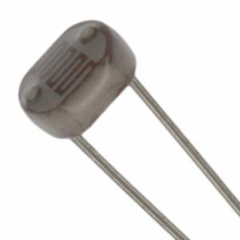 It's a PDV-P8104,
a photoconductive photocell. I couldn't find an smd version so I just use this.
It's a PDV-P8104,
a photoconductive photocell. I couldn't find an smd version so I just use this. Then I made a hello light board, based on Neil's version of the board. The tricky part was that I only have an Attiny44a-SSU here in my lab because the Attiny45's were all used up, I needed to improvise with my little experience and no help. It was very hard but I came up with a design. I threw it away (you can still download it if you like) because when I switched labs, I suddenly had the Attiny45, so here is my *~new~* design:
This is what it looked like in the beginning:
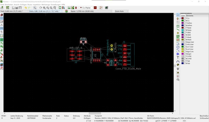
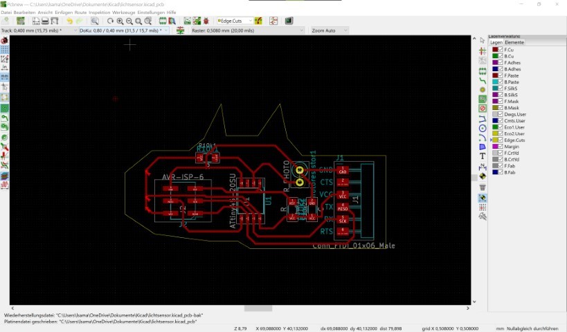
And this is what the board looks like now:
And here are my parts:
- 1 SMD Capacitor 1uF (1206)
- 1 FTDI SMD 01x06 Male Pinheader (2.54mm)
- 1 ISP SMD Pinheader (2x03, 2.54mm)
- 1 THT Photoresistor
- 2 10K Ohm SMD Resistor (1206)
- 1 ATTiny45-20SU
So as I already thought, the milling process on the LPKF was a pure desaster and I never want to use this machine again. I switched labs to be able to still mill pcbs.
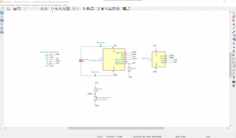
Luckily a nearby lab took me in and I could mill on a cheap tabletop mill. It was a very good experience! I would trade that expensive pcb mill to a cheap chinese mill in a heartbeat! I also switched Eagle to KiCad and I really like it. The designing process is really similar to eagle but the export is a lil' different. To plot you need to go to the plot button on the upper right corner.
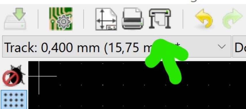
This window should come up:
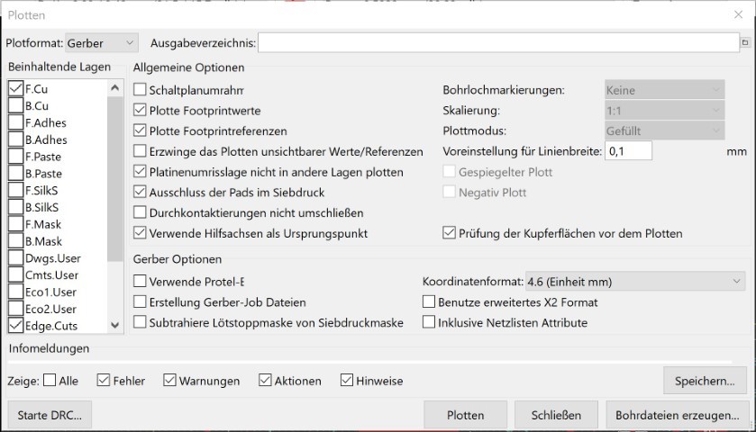
And those are the settings I used:
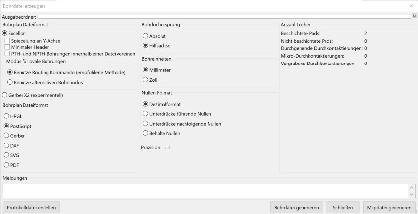
To get those nice drill and cut files to your machine, you need to convert it to cnc-files. I used FlatCam for this. It wasn't perfect but it does it's job okay (for my use).
.....
And after all that you can load it into Estlcam and send it to your machine.
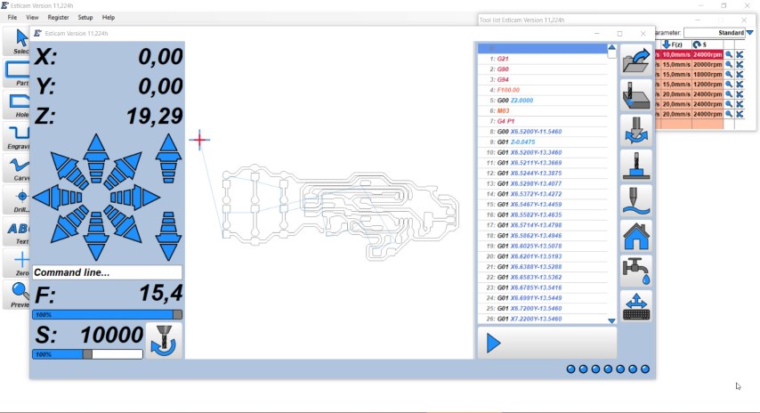
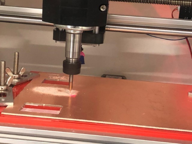
Here you can see the mill in action:
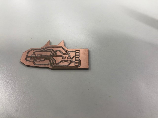
And this is the result! It looks perfect, I just need to rub it against some fleece and place my components on it. Now it's starting to be fun again.
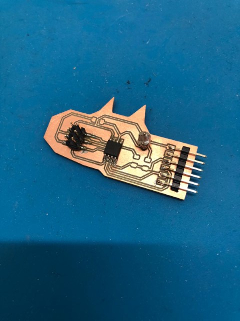
First test- flashing works at this stage. So now I can place the rest. I recommend it to everyone who had prior problems with flashing their boards-like me.
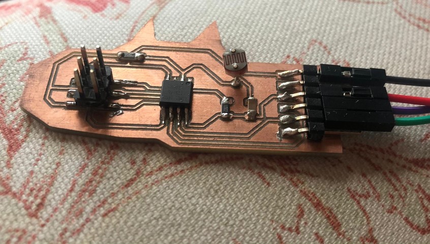
And here you can see it done.
Programming
I flashed it using this library with these specs: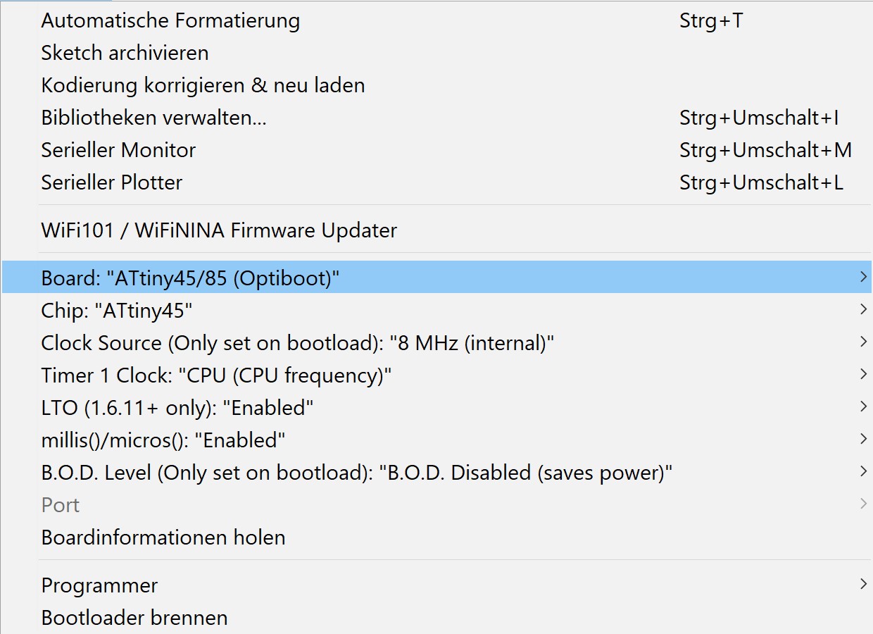
Since I can't test it using an onboard LED, I used the software serial instead:
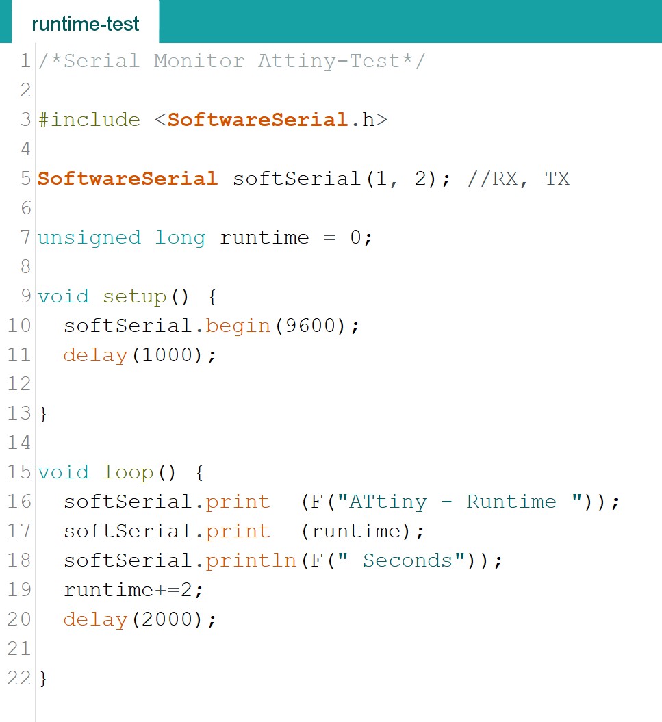
I highly recommend doing this because it makes it easier to have an overview of your board. Just open the serial, turn it to 9600 BAUD and you're done.
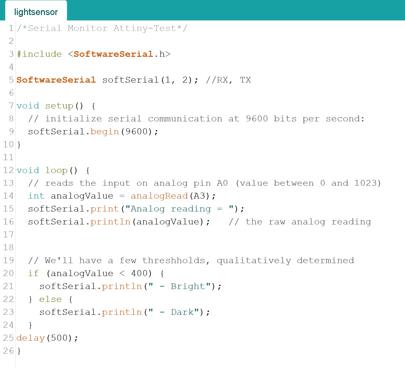
To program the photocell, I made the following code:
Testing
This is how I connected it to the pc (to be able to use the serial):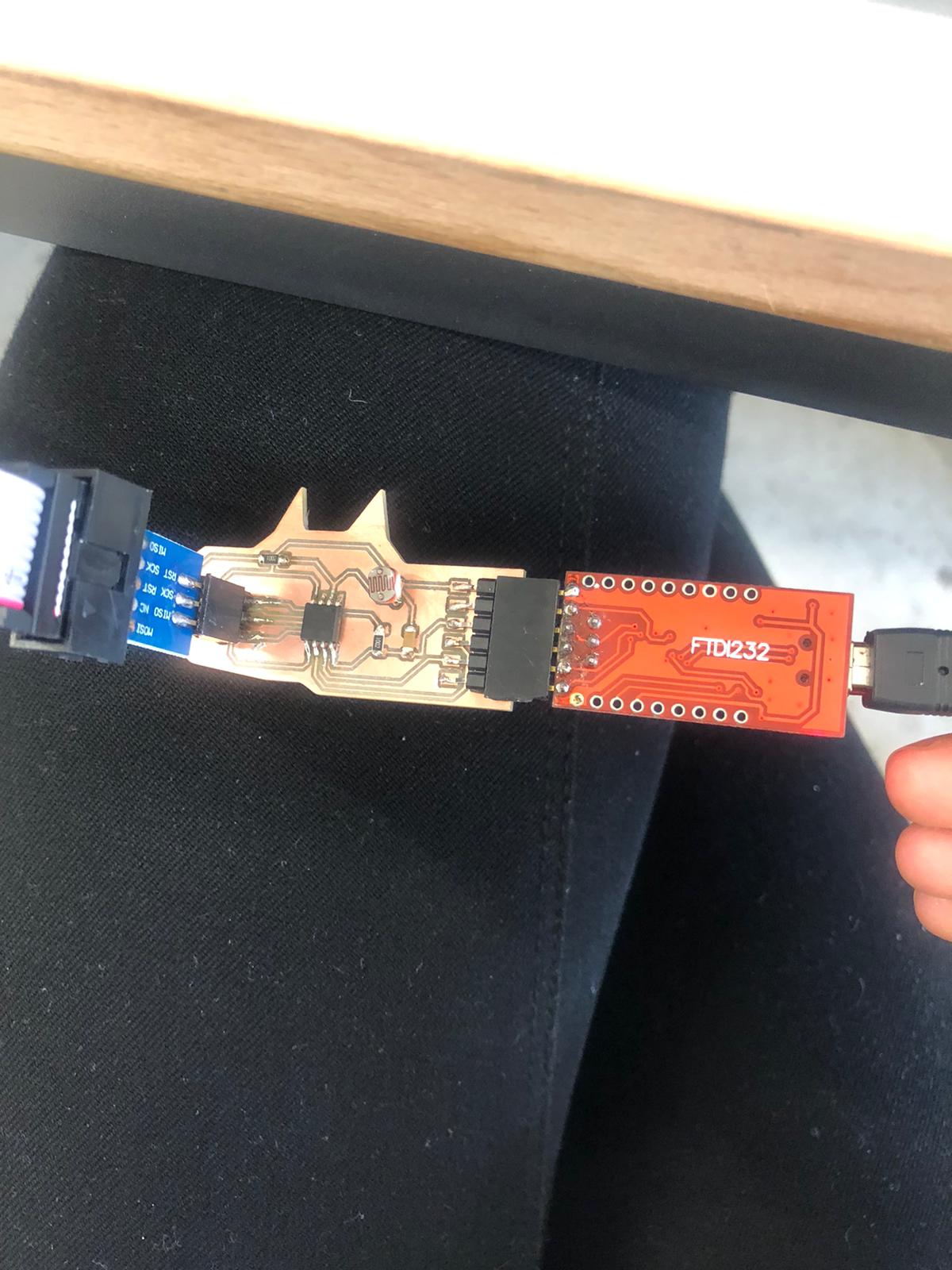
This is how it operates. When I keep the board in the dark, the serial says that it's dark. If I make it bright again, it says "bright".