13. Networking and Communications
In this Networking and Communications week individual assignment was to design, build, and connect wired or wireless node(s) with network or bus addresses. For the first part I decided to use I2C LCD module to work with I2C communication, I also wanted to try 1-wire communication by connecting three digital temperature sensors into network. For the group assignment we had to send a message between two projects.
LCD I2C display
A typical I2C LCD display consists of a HD44780 based character LCD display and an I2C LCD adapter. A 16×2 character LCD, used in this example, has an LED backlight and can display 32 ASCII characters in two rows with 16 characters on each row. You can see in a picture bellow.
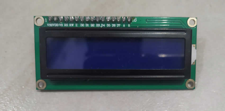
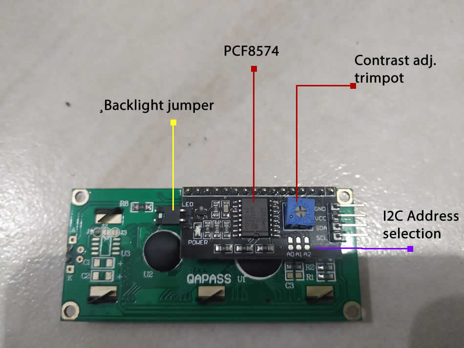
At the heart of the adapter is an 8-Bit I/O Expander chip – PCF8574. This chip converts the I2C data from an Arduino into the parallel data required by the LCD display. Except Extender chip, the board comes with a small trimpot to make adjustments to the contrast of the display. There is also a jumper on the board that supplies power to the backlight.
I2C LCD display has only 4 pins:
- GND – ground pin
- Vcc – 5V power supply
- SDA – Serial dana pin, this line is used for both transmit and receive
- SCL – Serial clock pin, timing signal
Little more about I2C address of LCD. The board has three solder jumpers (A0, A1 and A2). Each of these is used to hardcode the address. If a jumper is shorted with a blob of solder, it sets the address. By shorting the solder jumpers we get a range of all possible addresses that spans from 0x20 to 0x27. You can see a picture bellow.
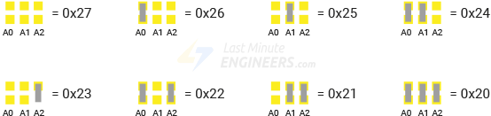
This site was very helpful with I2C address of LCD. My I2C address is 0x27.
On the following picture you can see timing diagram of I2C communication (img source: wikipedia.org).

- Data transfer is initiated with a start condition (S) signaled by SDA being pulled low while SCL stays high.
- SCL is pulled low, and SDA sets the first data bit level while keeping SCL low (during blue bar time).
- The data are sampled (received) when SCL rises for the first bit (B1). For a bit to be valid, SDA must not change between a rising edge of SCL and the subsequent falling edge (the entire green bar time).
- This process repeats, SDA transitioning while SCL is low, and the data being read while SCL is high (B2, …Bn).
- The final bit is followed by a clock pulse, during which SDA is pulled low in preparation for the stop bit.
- A stop condition (P) is signaled when SCL rises, followed by SDA rising. In order to avoid false marker detection, there is a minimum delay between the SCL falling edge and changing SDA, and between changing SDA and the SCL rising edge. Note that an I2C message containing N data bits (including acknowledges) contains N+1 clock pulses.
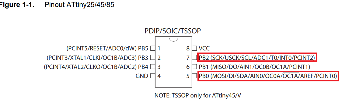
So, how to connect i2C LCD to my microcontroller ATtiny85 board from input devices week?
After reading the datasheet I found out that this mcu has USI (Universal Serial Interface) that needs to be configured as I2C or TWI (two wire interface). It has SDA and SCK on pin PB0 i PB2.
After some reading I found some libraries that works with arduino I2C. I connect ATtiny85 with I2C LCD display in a following way:
| ATtiny85 | LCD I2C display |
|---|---|
| Vcc | Vcc |
| GND | GND |
| PB0 | SDA |
| PB2 | SCK |
To program microcontroller I used TinyWireM library, ATtiny85 as a master and LCD as a secondary, and following code in arduino.
#include <TinyWireM.h>                  // I2C Master lib for ATTinys which use USI
#include <LiquidCrystal_I2C.h>          // for LCD w/ GPIO MODIFIED for the ATtiny85

#define GPIO_ADDR     0x27              // address of LCD
LiquidCrystal_I2C lcd(GPIO_ADDR, 16, 2); // set address & 16 chars / 2 lines

void setup() {
  TinyWireM.begin();                    // initialize I2C lib
  lcd.init();                           // initialize the lcd
  lcd.backlight();                      // Print a message to the LCD.
}

void loop() {
    lcd.clear();
    lcd.print("FabLab I2C test");       // display it
    delay (2000);
    lcd.clear();
    delay (2000);
}
You can see results of a working LCD in a video bellow.
1-wire communication
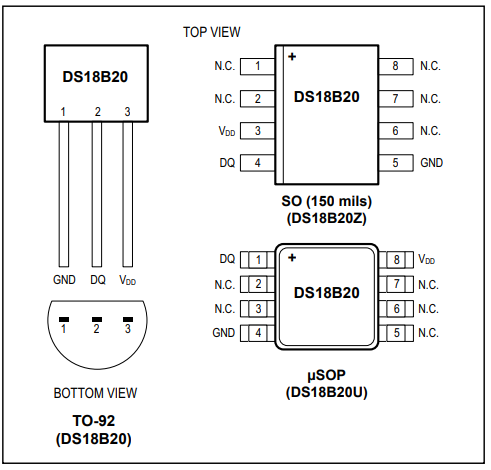
For the next task I wanted to try 1-wire communication by interfacing multiple DS18B20 digital temperature sensors with microcontroller. The basis of 1-Wire technology is a serial protocol using a single data line plus ground reference for communication. A 1-Wire master initiates and controls the communication with one or more 1-Wire secondary devices on the 1-Wire bus. Each 1-Wire slave device has a unique, unalterable, factory-programmed, 64-bit identification number (ID), which serves as device address on the 1-Wire bus. The 8-bit family code, a subset of the 64-bit ID, identifies the device type and functionality. The DS18B20 digital thermometer provides 9-bit to 12-bit Celsius temperature measurements and has an alarm function with nonvolatile user-programmable upper and lower trigger points. The DS18B20 communicates over a 1-Wire bus that by definition requires only one data line (and ground) for communication with a central microprocessor. In addition, the DS18B20 can derive power directly from the data line (“parasite power”), eliminating the need for an external power supply. I used three temperature sensors in TO-92 package with the pinouts described bellow
I started by connecting all the DS18B20 in parallel (common all the VDD pins, GND pins & signal pins). 1-wire bus I set to be PB2 pin on ATtiny85.
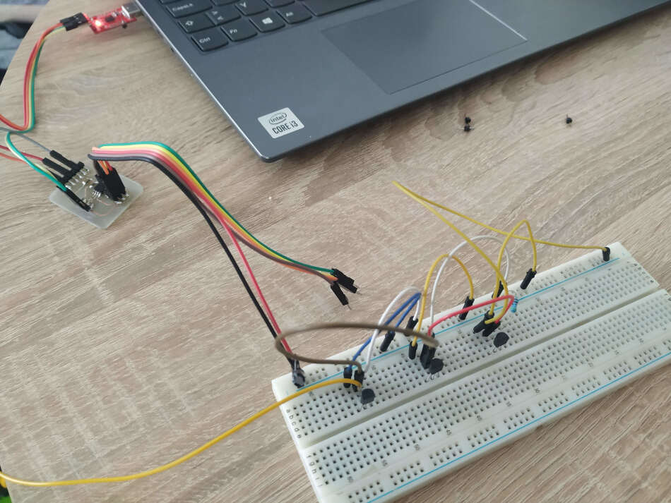
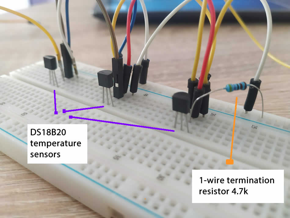
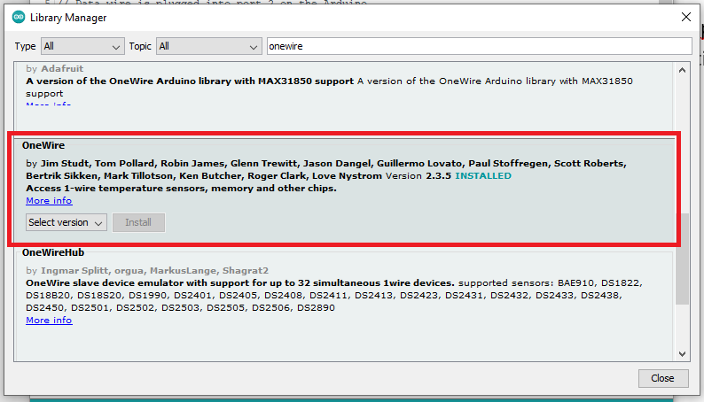
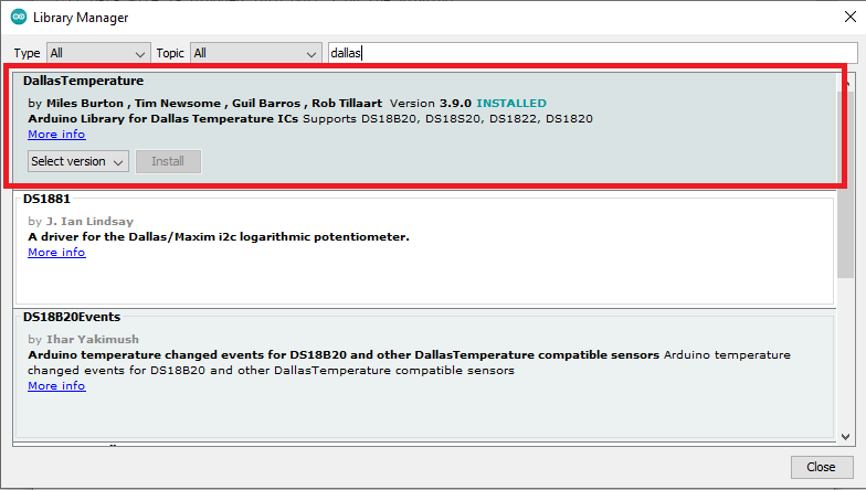
I also added one 4.7k pull-up resistor for whole bus between the signal and power pin to keep the data transfer stable. In order 1-wire to work I needed to add a onewire and dallas temperature library in arduino.
Each DS18B20 has a unique 64-bit address assigned to it to differentiate them from one another. I uploaded a sketch to find out the addresses of each sensor. Because ATtiny85 does not have a hardware serial I needed to use SoftwareSerial to display addresses.
—scan sketch
#include <OneWire.h>
#include <DallasTemperature.h>
#include <SoftwareSerial.h>

// Data wire is plugged into port 2 on the Arduino
#define SERIAL_RX 3
#define SERIAL_TX 4
#define ONE_WIRE_BUS 2

// Setup a oneWire instance to communicate with any OneWire devices
OneWire oneWire(ONE_WIRE_BUS);

// Pass our oneWire reference to Dallas Temperature.
DallasTemperature sensors(&oneWire);

// variable to hold device addresses
DeviceAddress Thermometer;

SoftwareSerial TinySerial(SERIAL_RX, SERIAL_TX);

int deviceCount = 0;

void setup(void)
{
  // start serial port
  TinySerial.begin(4800);

  // Start up the library
  sensors.begin();
}

void loop(void)
{
  if (TinySerial.available()) {
    TinySerial.println("Locating devices...");
  TinySerial.print("Found ");
  deviceCount = sensors.getDeviceCount();
  TinySerial.print(deviceCount, DEC);
  TinySerial.println(" devices.");
  TinySerial.println("");

  TinySerial.println("Printing addresses...");
  for (int i = 0;  i < deviceCount;  i++)
  {
    TinySerial.print("Sensor ");
    TinySerial.print(i+1);
    TinySerial.print(" : ");
    sensors.getAddress(Thermometer, i);
    printAddress(Thermometer);
  }
  }
  }

void printAddress(DeviceAddress deviceAddress)
{
  for (uint8_t i = 0; i < 8; i++)
  {
    TinySerial.print("0x");
    if (deviceAddress[i] < 0x10) TinySerial.print("0");
    TinySerial.print(deviceAddress[i], HEX);
    if (i < 7) TinySerial.print(", ");
  }
  TinySerial.println("");
}
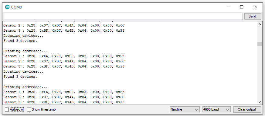
I found three different address, you can see it in a picture bellow.
After that I uploaded the sketch that reads the temperature from DS18B20s by their addresses.
#include <SoftwareSerial.h>
#include <OneWire.h>
#include <DallasTemperature.h>

#define SERIAL_RX 3
#define SERIAL_TX 4
#define ONE_WIRE_BUS 2

// Setup a oneWire instance to communicate with any OneWire devices
OneWire oneWire(ONE_WIRE_BUS);

// Pass our oneWire reference to Dallas Temperature.
DallasTemperature sensors(&oneWire);

SoftwareSerial TinySerial(SERIAL_RX, SERIAL_TX);

// Addresses of 3 DS18B20s
uint8_t sensor1[8] = { 0x28, 0xFA, 0x78, 0xC9, 0x03, 0x00, 0x00, 0xBE };
uint8_t sensor2[8] = { 0x28, 0x37, 0xDC, 0x4A, 0x04, 0x00, 0x00, 0x6C };
uint8_t sensor3[8] = { 0x28, 0xBF, 0x0C, 0x4B, 0x04, 0x00, 0x00, 0xF6 };

void setup(void)
{
  TinySerial.begin(4800);
  sensors.begin();
}

void loop(void)
{
  sensors.requestTemperatures();

  if (TinySerial.available()){
  TinySerial.print("Sensor 1: ");
  printTemperature(sensor1);

  TinySerial.print("Sensor 2: ");
  printTemperature(sensor2);

  TinySerial.print("Sensor 3: ");
  printTemperature(sensor3);

  TinySerial.println();
  delay(1000);
  }
}

void printTemperature(DeviceAddress deviceAddress)
{
  float tempC = sensors.getTempC(deviceAddress);
  TinySerial.print(tempC);
  TinySerial.print((char)176);
  TinySerial.print("C  |  ");
  TinySerial.print(DallasTemperature::toFahrenheit(tempC));
  TinySerial.print((char)176);
  TinySerial.println("F");
}
Adventures in wireless communication
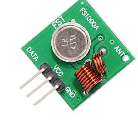
This is something that I made a couple years ago. I was interested in wireless technologies and possibilities. I came across this article from Samy Kamkar where he hack a wireless doorbell to ring whenever he send a text message to the device. So, I tried the same but without GSM module to see if it will work. I had one cheap and simple wireless module (FS1000A) that transmit a signal on 433 MHz. It has three pins, Vcc (5V), GND and signal.
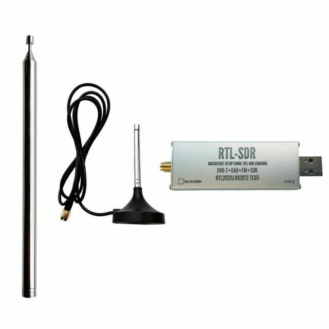
I also had a RTL-SDR USB stick. RTL-SDR is a very cheap ~$25 USB dongle that can be used as a computer based radio scanner for receiving live radio signals in your area (no internet required). Depending on the particular model it could receive frequencies from 500 kHz up to 1.75 GHz.
Software-defined radio (SDR) is a radio communication system where components that have been traditionally implemented in hardware (e.g. mixers, filters, amplifiers, modulators/demodulators, detectors, etc.) are instead implemented by means of software on a personal computer or embedded system.
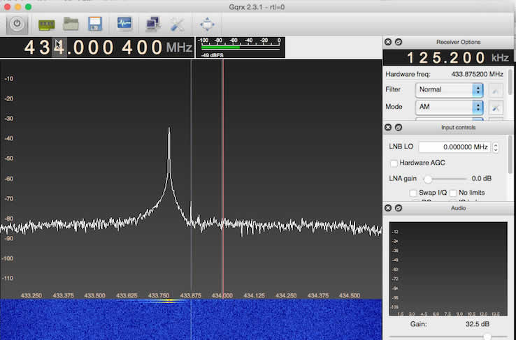
First thing I needed to do is to record original transmitter code. For this you can use software like SDR# or GQRX. When I activate original transmitter you can see spikes in a graph. That’s been recorder and saved. After analyzing the signal we can see that transmitter uses something called On-Off Keying, or OOK, which is a type of Amplitude Shift Keying (ASK). (img source: Samy Kamkar)
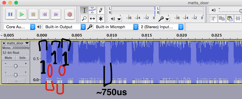
When I recorded signal, now it’s time to decode. I opened recorded file in Audacity and observe the signal. You can see pulses that represents “0” and “1”. You can also see delay between them. (img source: Samy Kamkar)
Next thing is to incorporate all that and program Arduino. I simply connect wireless module and push button with arduino. I modified a little bit of Samy’s code to work when I press push button. It works. You can see it in a video bellow.
Group Assignment
For the group assignment we had to send a message between two projects, so I chose two of my previously made boards (PCB’s from input devices week). Left one was the master and the right one the secondary.
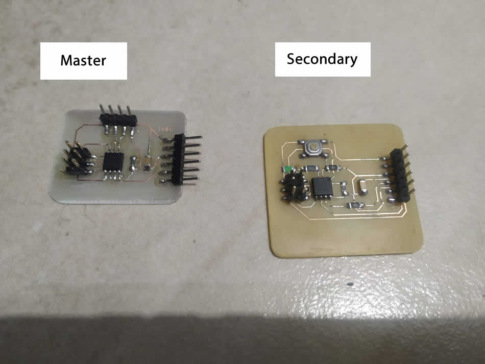
I deceided to send a message over I2C protocol. I already added a TinyWireM library for master so I needed to add a library TinyWireS for secondary device. I found it here. On my secondary device I have LED so I send a message to turn the LED on and off every two seconds. I also used SoftwareSerial to output message in serial monitor. This site was very helpful with sending message between two ATtiny’s (Thanks Xavier).
Here is the master code.
#include <TinyWireM.h>
#define device (1)
#define SLAVE_ADDR 0x6 //define the address for the slave

#include <SoftwareSerial.h>//add library to be able to use the serial monitor
int rxPin = 4; //the receiving pin
int txPin = 1; //the transmitting pin
SoftwareSerial serial(rxPin, txPin); // to set up the serial object

void setup() {
  TinyWireM.begin();
  pinMode(rxPin, INPUT); //the rx pin is the input of the communication
    pinMode(txPin, OUTPUT); //the tx pin is the output of the communication
    serial.begin(4800); //begin communication with computer
}

void loop() {
  TinyWireM.beginTransmission(SLAVE_ADDR);
  TinyWireM.send(1);
  TinyWireM.endTransmission();
    msg();//receive message
  delay(2000);

  TinyWireM.beginTransmission(SLAVE_ADDR);
  TinyWireM.send(0);
  TinyWireM.endTransmission();
    msg();//receive message
  delay(2000);
}


  void msg()
  {
    volatile byte msg =0; //treat as variable
    TinyWireM.requestFrom(SLAVE_ADDR,1);//request from slave address

    if (TinyWireM.available()){ //to make sure the master is available
    msg = TinyWireM.receive();//receive message

      if (msg ==4){//if this message
      serial.println("It's day!");}//print this in serial monitor
      else if (msg ==5){//if this message
      serial.println("It's night!");}//print this in serial monitor
      }
  }
And here is a code for the secondary.
#include <TinyWireS.h>
#define output (4)
#define I2C_SLAVE_ADDR 0x6

void setup() {
  // put your setup code here, to run once:
  TinyWireS.begin(I2C_SLAVE_ADDR);
  pinMode(output, OUTPUT);
}

volatile byte msg = 0;

void loop() {
    if (TinyWireS.available()){
    msg = TinyWireS.receive();

    if (msg == 1){
    digitalWrite(output, HIGH);
    TinyWireS.send(5); //send message
    }
    else if (msg == 0){
    digitalWrite(output, LOW);
    TinyWireS.send(4);//send message
    }
  }
}
After I uploaded master and secondary code nothing happend. Does not work. So then I was checking code and connection between ATtiny’s. I have not connect a two 4.7 kΩ resistors between SDA, SCK pins and ground. After I connect those two resistors everything worked. You can see it in a video bellow.
Useful links: