9. Mechanical design, Machine design
In this two weeks we had to design a machine that includes mechanism+actuation+automation. We needed to build the mechanical parts, operate it manually and actuate and automate our machine. We also need to document the group project and our individual contribution.
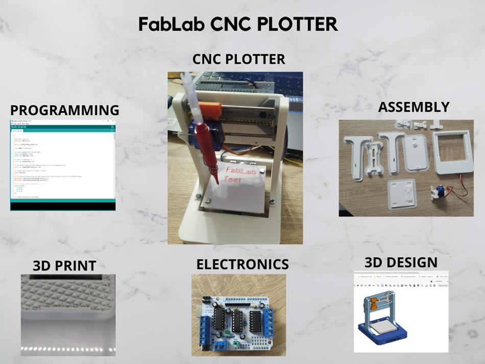
Because Tatjana and I working remotly, we decided to work together on this project. We started researching what kind of machine to make. We decided to make a mini CNC plotter. Our project consist of 4 phases:
- 3D design of the machine
- 3D printing parts
- Assembly
- Electronics and programming
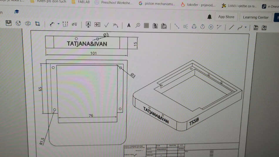
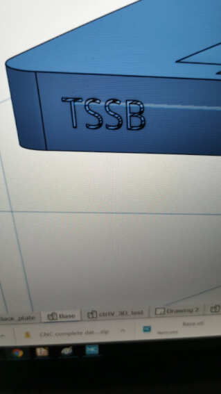
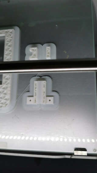
Tatjana did 3D design and 3D printing of parts, while I did assembly and programming the electronics. We watched and researched on the internet how to design a plotter. We opted for a smaller plotter given the parts we had. Tatjana started design machine base in OnShape. She added holes, position for frames and our names. You can see it in a picture bellow.
She also engrave our school logo
Tatjana continued to model frames, rails, sliders and base. We have Y plate bellow and one other plate for electronics. Finished design can be seen in a picture bellow.
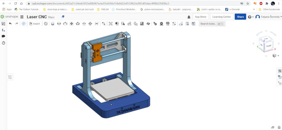
The missing part in this design is the pen holder. We were thinkig to mount it on X axis but the part was too big so we couldn’t use it on such a small machine. After design Tatjana started print the parts.
We deceided in the end not to put this pen holder because it was to big. The details about design and 3d printing can be seen on Tatjana’s page or group assignment page.
Parts and assembly
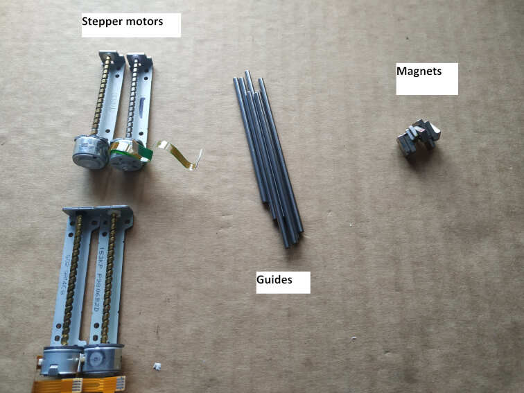
We decided to find parts for our machine in old dvd/cd roms and burners. I had 4 units that should be enough.
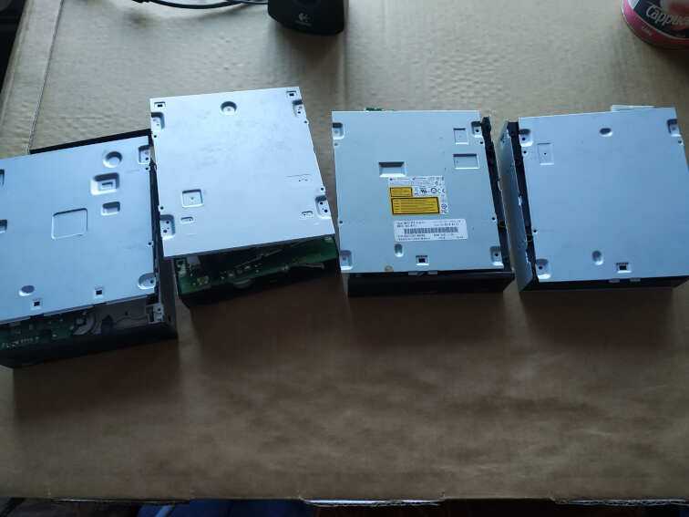
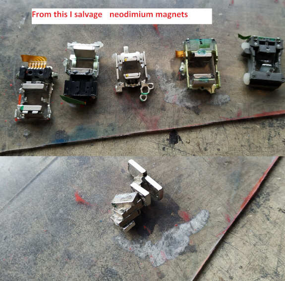
I disassembled the old cd/dvd roms and pulled out the stepper motors, guides and neodymium magnets. Magnets was glued in some kind of hausing with optics. I carefully detached the magnets from the case, not to damage them. Later I used them on the machine as well.
The good thing is that stepper motors comes with threaded spindle. For the machine I used stepper with longer threaded spindle. These are the ones bellow. The guides were different sizes (different lenght). I took the four guides with longest lenght.
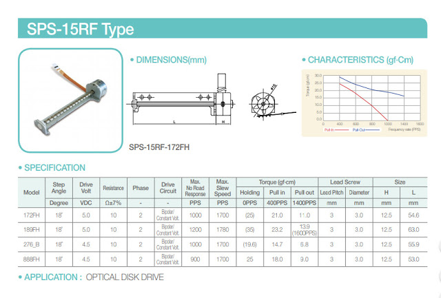
I tried to find more information about the stepper motors. I found similar type of stepper. It has a step angle of 18 degree and operating voltage 5V.
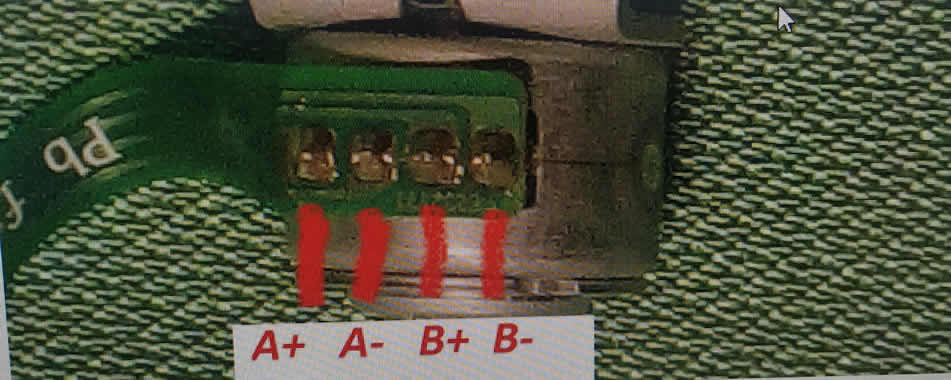
These motors are bipolar stepper motors with four wires. I needed to find same coil wires. I used multimeter in resistance mode to find matching pair. You can see it in a picture bellow.
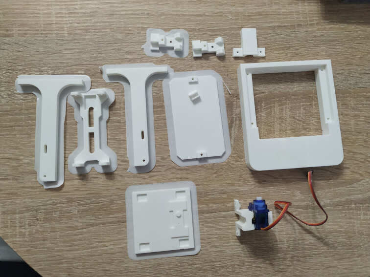
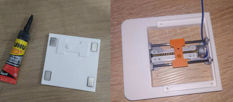
Now it’s time to assemble the machine. This is all the parts that needs to be assembled. I removed the raft from parts and started assembly.
I used magnets and glued them on Y plate bellow. This is because when machine start plotting we can put other magnets on paper to hold it. I also inserted rails and guides through holes together with slider on Y axis. It’s important that slider can be operated with hand easily.
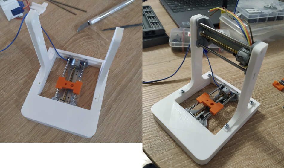
I continued to add left and right frame, X axis rail, guides and slider. Here you can see that some parts are different colors. This is because when I assembled some parts break so we needed to print them again.
I added back plate behind X axis for electronics using double stick tape. On back plate I put Arduino Uno and screwed with two screws. On top of arduino uno goes motor shield.
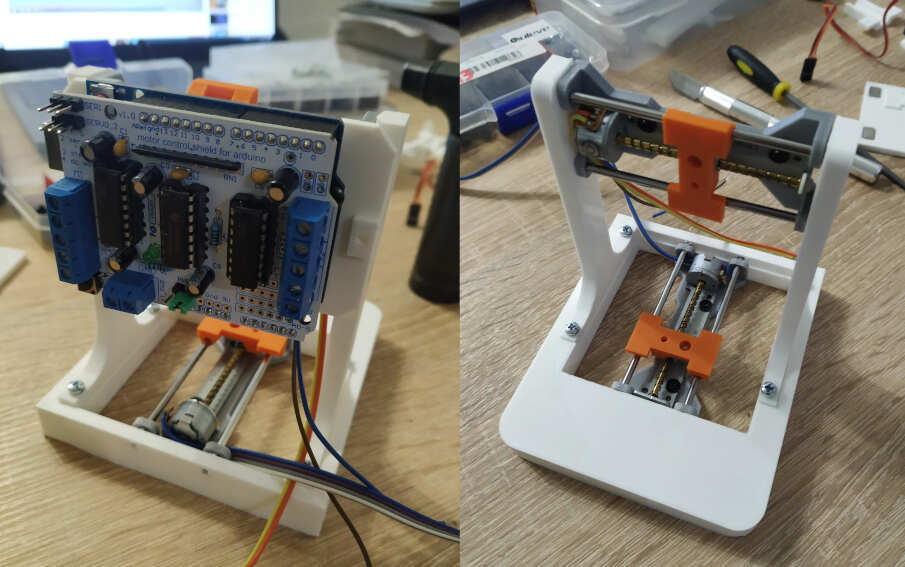
For controlling steppers I used Velleman L293D motor shied for arduino uno. User manual can be found here. The shield can power up to 4 DC motors or 2 stepper motors. It also have connection for 2 servo motors.
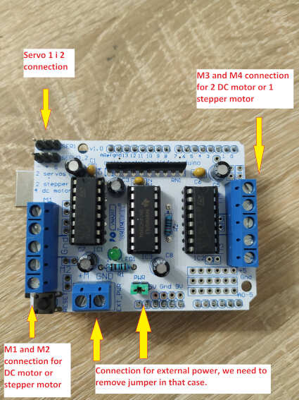
I connect one stepper to M1 and M2, other stepper to M3 and M4 markings on the shield. I used external supply and set 5V, so I needed to remove jumper in order to use external supply. We need to use external supply because of the high current that motors consumes. You can see schematic bellow.
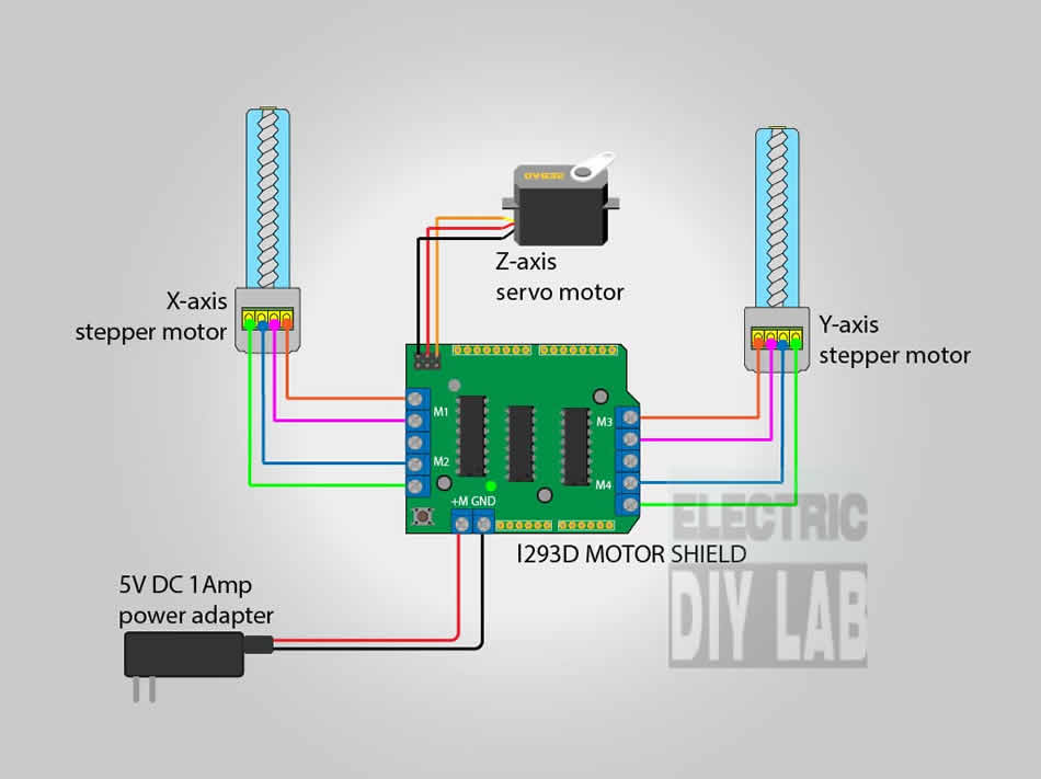
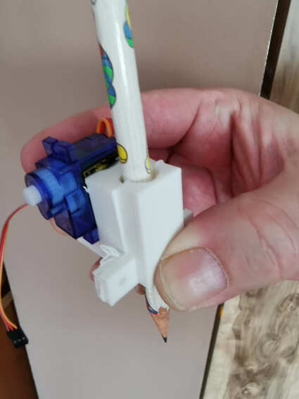
I hot glued servo on X slider and put a pen. I connected servo and pen with steel wire.
Programming and testing
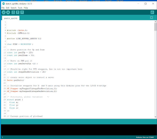
Now when all is connected it’s time to program Arduino so that we can communicate with the machine over Gcode. I used sketch based on GBRL. It’s important to add a library from AdaFruit, AFMotor library in order to work. More info about the library can be found here. In arduino sketch I changed steps per pervolution to 20 (from the datasheet above).
Next, I opened a Processing sketch for controling the machine. I had to test the axis. We can jog X and Y axis and Z just up and down. You can see in a video axis test
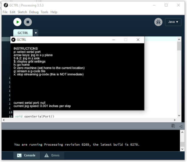
Axis test
This CNC plotter machine works on absolute positioning. Absolute coordinates are defined as each position on the work piece is unique. With the absolute coordinate system, the origin is the currently active program zero point. If fixture offset number one is active (machining center), then the absolute position display will show how far each axis is from the program zero point specified by fixture offset number one.
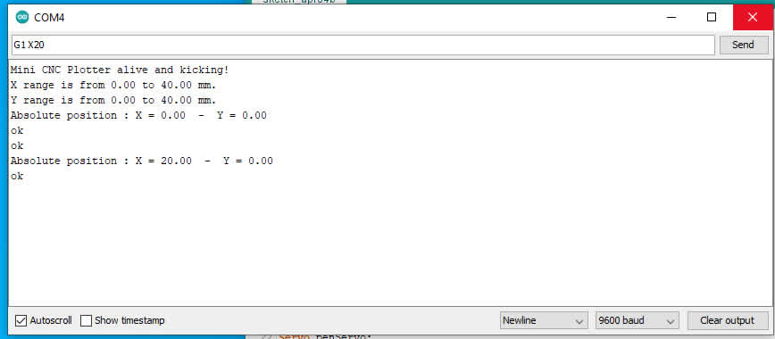
I can send directly Gcode to the machine through serial monitor. So if I type M114, I get current position. For moving the axis I can type G1 X20. That means linear moving on X axis 20mm. You can see the full list of Gcode commands here.
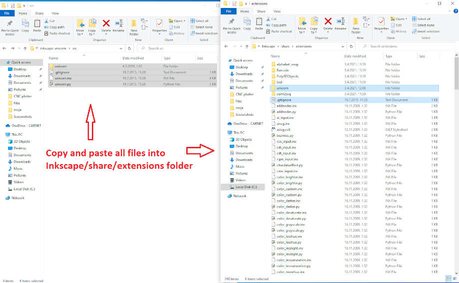
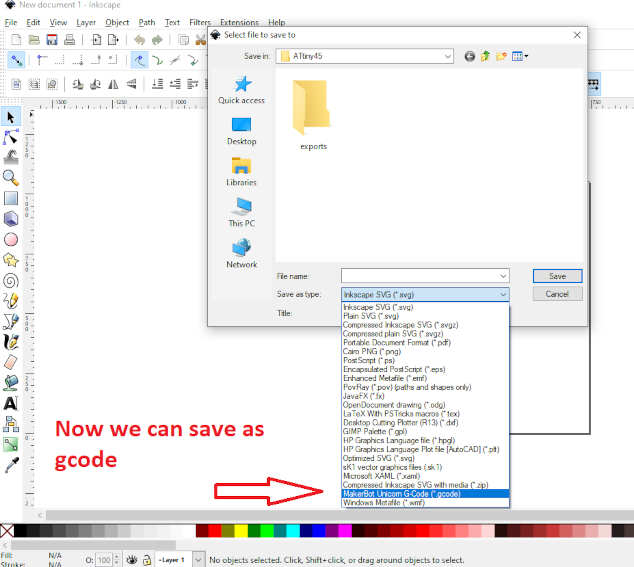
I wanted to create my own Gcode for the machine so I install unicorn plugin for Inkscape written in python.
In document properties unit needs to be set to cm (centimeters) and custom size of 8x8 cm.
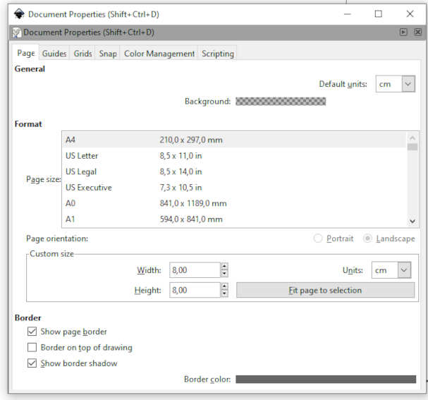
I wrote a simple text and set size of 4x4cm. Before saving to Gcode we need to convert it to path. This setting are important for proper generation of Gcode. First i did not set this for the first time and had issues with the machine. Machine was not working properly. After I changed settings than it was good. One other note is that Inscape version was 0.47. I dont know if this plugin works on newer versions of Inkscape.
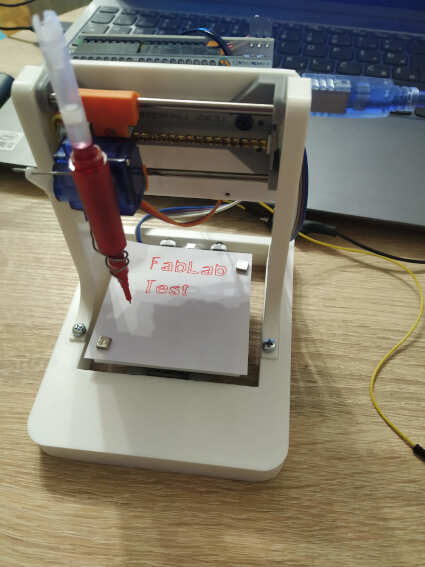
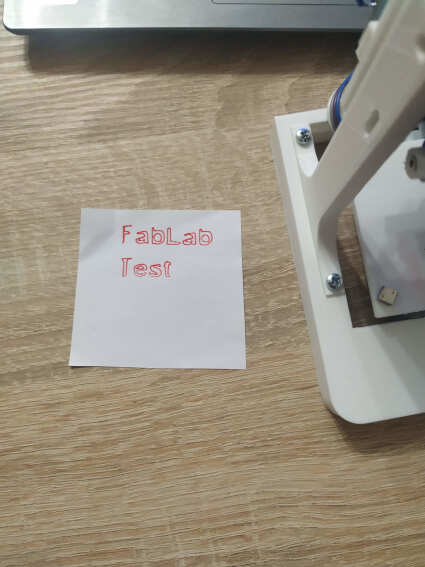
This is the results and finished machine.
At the end…
There is certainly space for improvement, especially with the pen accessory. We plan to develop that. This was a fun project. I learned a lot. It would be good to try to draw directly on the pcb with this CNC plotter.