Project development
This pages summarizes and centralize the information on the developments and iterations made on the final project week per week.
Week 1 - Brainstorming and proposing a first draft
This first week was dedicated to the draft of the final project. The complete description of my first ideas can be found in the description of the week 1 assignment.
Basically, I want to do a 3D tracking and characterization system for continuum Soft Robots.
Why this project
I have a lot of interest in soft robots. I study these soft robots for endoscopy and minimally invasive surgery. Thin, long, and actuated tube (catheters) can be used as navigation tools via the natural pathways, to reach remote locations of the body. These soft actuated tubes must be thin and able of complex movements, as tentacles. In order to assess the potential of the soft robots, they must be fully characterized, using typically the angles and curvature radius generated.
 Steerable soft catheter could allow new opportunities in endoscopy
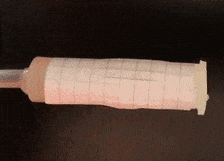
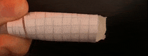
 Example of a soft robot I made able to bend in one direction
Key features of the setup
- Structure: A support to fix the actuator
- Output: A pressure source to actuate the soft robot
- Input: A 3D scan sytem for the tracking (ideally real-time)
- Control: An interface for the
- And a soft actuator to test the setup
First sketch
 First sketch of the tracking system
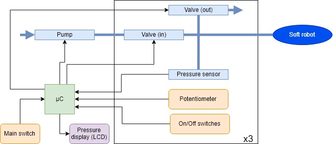
 Block diagram of the final project
The 3D tracking system must still be defined. The first idea is to use a single camera with one mirror to capture the actuator from two angles. It should then be possible to reconstruct the 3D position. A real-time system would be advantageous but is not mandatory. The modularity is an important feature of the project (size of the structure, possibility to change sensors, …)
Useful skills
This project will use a lot of the skills developed during the various lessons of the fab academy:
- Electronics (control and tracking board)
- Embedded programming (µC programming)
- CAO (design, structure)
- 3D scanning (tracking)
- Output devices (pressure source, display)
- Laser cutting (structure)
- 3D printing (structure)
- Moulding (continuum soft robot)
- Interface programming (control interface)
- …
Resources
I have already identified several resources that will be useful during the project.
- Soft Robotics Toolkit
- Interesting papers:
- Fab Academy final projects:
My vision for this project
Soft and continuum robots are gaining interest for many application, for biomedical application as wearables or surgery devices, but also for other applications as grippers or locomotion. Such a low-cost and well resourced modular tracking platform could be interesting for the characterization of many designs. As an example, this project could be integrated in the complete Soft Robotics Toolkit.
Week 2 - Discussing my project with the Fab Lab team
I had the opportunity to discuss my project and to have short feedbacks from the members of the Fab Lab ULB.
My projects includes several aspects, one of which being 3D tracking, to measure the position and the curvatures of my soft robot. I am a complete rookie in this field, but fortunately, Adrien, the fab manager, has some contact from the digiscope in Paris.
Week 3 - Designing a first version of the structure
This week was about computed-aided design. I designed a first version of the structure of the project on FreeCAD (the part that supports the soft robot).
Week 4 - Building ideas for the structure
No breakthrough this week, but some new ideas and possibilities. The press-fit assembly was a success, and I will keep this in mind when I’ll develop fully the structure! This is documented in the week 4 assignment.
Week 5 - Some more inspiration
Some more inspiration: the photoboxes
Week 6 - First draft of the 3D tracking
This week was about 3D printing and Scanning, so I decided to begin my “3D reconstruction software”. Here is the workflow I imagine to do it.
All the documentation of the work done this week can be found here.
Week 8 - Moving on on the structure
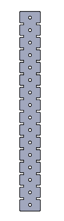
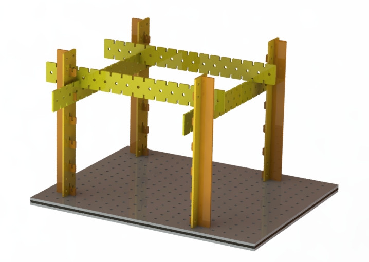
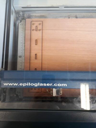
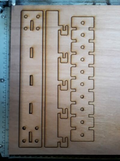
After a week 7 spent on KiCAD, the week 8 was about making something big with the CNC. My first idea was to make the structure that I already designed a little bit in week 3. However, this is not really “big” and this would be more suitable to make with the laser cutter, so I worked a little bit on the structure, but aside of the assignment. I liked the simple and modular structure that I proposed in week 3, but the extruded profiles cannot be made (of course) in a fab lab. So, I tried to design an alternative. I replaced the profiles by 3 types of pieces, 2 vertical and 1 horizontal. This is not a “clean” design, but this is supposed to be as modular as possible. I tried first with FreeCAD, using multiple files sharing a “master spreadshet”, but the too many bugs and the often closing software convinced me to let it go and use Solidworks, a tool that I master. Note that I also tried Fusion 360 this week, and it was not really a success neither. I also re-designed the “home-made” optical board inspired by Denis, my instructor, that I developed a little bit in week 3. Of course, I made all the design perfectly parametric.
Week 10 - Making demonstrators
This week was not really about the final project, but I made some demonstrators, illustrating similar working principles than my soft robots. It will also be possible to my final project with them.
Week 11 and 12 - Going deeper in the final project
Pressure control board
This weeks are more closely related to the final project. As explained in detail in week 11 and week 12, the aim is to make a pressure control board for my structure. This week work is greatly inspired from the control board of the soft robotics toolkit. Here is the schematics of the control board:
Looking a little bit in detail in the toolkit, I found this pages, which describes a project very similar to my project!. It is not a complete surprise, since I know those kind of structures are used to characterize actuators, but I never saw this one, which will be a great inspiration for my final project. However, I want to make an even more “frugal” version of this characterization structure, and adapt it to my needs.
Improving the tracking and reconstruction program!
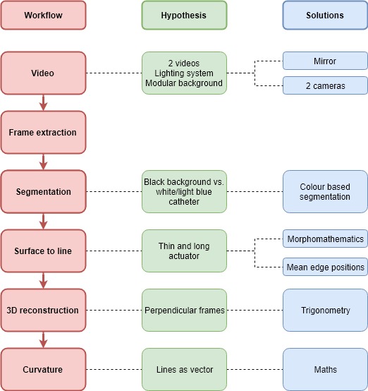
More than the control board, this week was dedicated to programming, and to extract the curvature radius from a test video of a catheter. Here is a schematic of the implemented workflow:
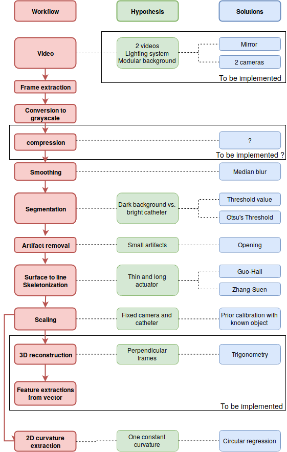
The implementation of the workflow used the open source library OpenCV. The two main sources were the following:
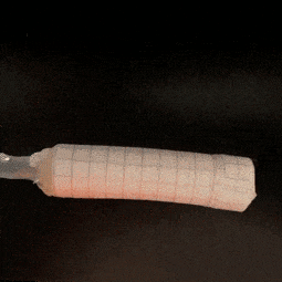
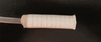
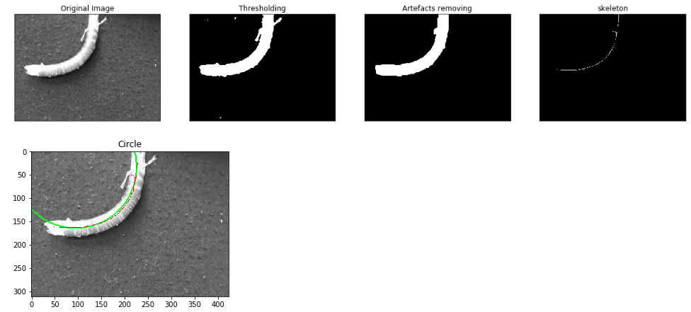
As shown on the diagram, not all the process has been implemented. However, as shown on the image below, the skeleton extraction has already been done! As a reminder, the big hypothesis here it that the catheter is considered as a line in the 3D space, so this skeleton extraction makes sense. Once all to coordinates of the skeleton have been extracted, I basically have a vector, and can imagine to compute almost any information from it (curvature of each point, position in 3D space, …). However, for the moment, and for the demonstration, I only worked on a 2D video. From the skeleton, I extracted the best fitting circle, which is a way to compute the radius of curvature of the catheter:
Concerning the scaling, I made a small algorithm allowing to compute the scale factor in mm²/pixel, by taking a picture (without moving the camera) of a rectangle of known size.
I implemented 2 solutions for the segmentation: using Otsu’s threshold or using a threshold based on a gray value. Even is the first one is more adaptive, it is an iterative algorithm, and consequently increase strongly the computational time.
Several limitations remain however:
- The program has only been tested on one test video. In particular, the capacity to handle other artifacts, or scenes with other illuminations could be problematic. A priori, the best solution will be hardware, by ensuring that the captured video can be exploited
- The synchronization of the frames with other data (typically the pressure) is not yet considered.
- Several parts of the workflow must sill be implemented.
- The computational time is for the moment a limitation. Two steps are limiting: the skeleton extraction, and to a lesser extend the smoothing/segmentation. Since it is difficult to modify those algorithms, two solutions can be considered: even trying other algorithms, even compressing the images at the beginning of the workflow (by reducing its size and/or quality). This will need to be tested, to ensure that no information is lost.
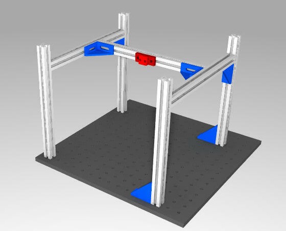
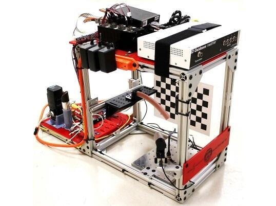
Testing the structure
This week, I also tried the structure that I designed in week 8, and which is documented on this page. For this, I used the same setup that in week 4. I made several tests (similar again than in week 4) to find good settings. I used left-overs of multiplex having a thickness of 5 mm. They were a little bit bent, but the aim here is mainly to test the structure.
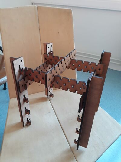
Good! This solution seems OK! I am not totally satisfied since I feel like the structure could be simpler, but this design is rigid enough for the moment, and is very modular! As a backup commercial plan, I still have the possibility to use aluminium profiles.
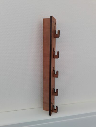
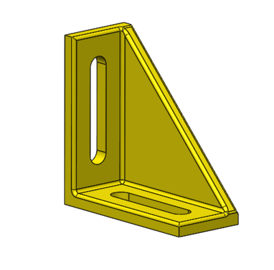
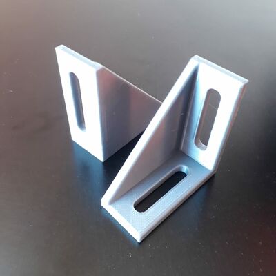
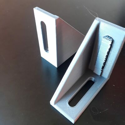
However, I still need fixations to fix the structure on optical breadboards. Here is the designed fixation, printed in 3D. I tried in parallel to print it with and without support, and the result was very similar, let’s avoid to waste material into supports!
Week 13 - Summarizing my final projects
This week is about documenting the final project! Basically, This is the perfect occasion to set things clear about it, and summarize what I documented here and during the various weeks in one clear and structured page.
From now on, I will try to document my final project advances directly in the newly created pages on the structure, on the pressure control, and on the tracking.
Week 14 - a lot of new development!
This week was about getting things from the last weeks done! I finished the input week and output week, and went even a little further! I documented all of it on the pressure control. Now all the prototyping for my inputs and outputs (excepted for the LCD) is done!
Week 15 - Questioning about the pressure source method… And adding some features!
As the control board of the soft robotics toolkit, I chose to use pump and valves to control the pressure… However, I am wondering if it is really the best solution. Indeed, using syringe pumps, as we plan to do for the group assignment would have two advantages in my solution:
- It seems at least as adequate seeing the small volumes and pressure required
- Is it way less noisy!
However, syringe pumps are also larger, and since I already have all the material for the valves and pump solution, I will continue on this path. However, If I have problems with this solution, I now have a good plan B! More, changing the pressure source would not change fundamentally my designs: all the inputs and the valves controller would not require any changes!
This week was also about getting the PCBs for the output in input done, as documented in the final project page, and testing an LCD display, as documented here
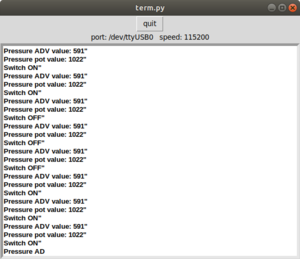
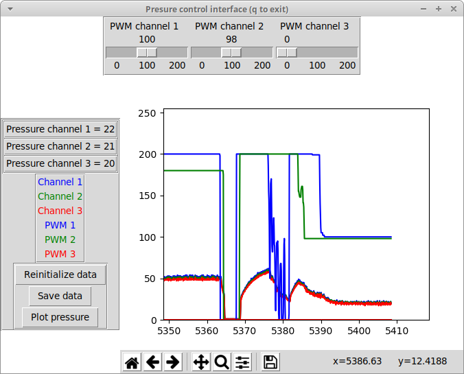
Week 16 - Making my pressure control system working, and adding an interface
Good week for my final project! I finished the “prototyping” phase, i.e. I tested my inputs and outputs boards, the pressure network, and the LCD, and I added some features and corrected some problems (for example by adding the pressure tanks to add inertia to the pressure system). And good news: my fears detailed will not lead to too big problems: the prototype works really good! This part is documented in the final project page. However, several points of attention remain, as the coupling between the channels.
The assignment of this week was about making an interface for the final project: also a good improvement! This part is documented here.
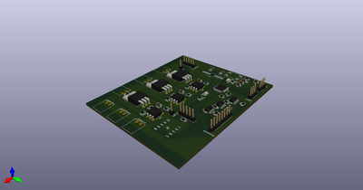
Week 17 and week 18 - making some other really nice projects… and a PCB!
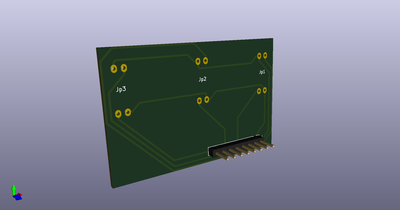
The week 17 and week 18 were fun, intense, and interesting, but leave no place for the final project. I just had a little time to do 2 PCBs, a new integrated board inspired by the satshakit, and a board for the pressure sensors.
Week 19 and 20 - working hard on the final project!
Those weeks were dedicated to the final project! Intense!
The week 19 page presents plans for dissemination and licensing of the project The technical development and the resources files are presented respectively on the pressure control board page, on the structure page, and on the tracking system page. And finally, the final project is summarized here