Embedded programming
Objectives of the week
- Individual assignment
- Read a microcontroller data sheet
- Program your board to do something, with as many different programming languages and programming environments as possible
- Group assignment
- Compare the performance and development workflows for other architectures
This week is again quite new! I already read datasheet and programmed chips, but in very guided way. I will have a lot to understand this week!
What I did
- Wrote very basic LED blinking c code
- Programmed my board using avrdude and my fabISP on Linux
- Programmed my board using Atmel studio and a commercial programmer on Windows 10
What I learned
- That Linux is cool, again
- I also better understood how does a microcontroller works and can be programmed
If I had the time to go further...
- I would have made fancier programs
- I would have try to understand assembler
Files and resources
- The final c code for the blinking can be downloaded here
- The final c code for the button can be downloaded here
Step 1: reading a datasheet
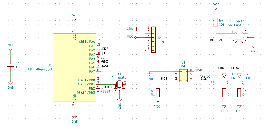
For this week assignment, I will use my board made in week 7. The AVR microcontroller is an ATtiny84A. As a reminder this is the design of my board:
Ready? Let’s read the datasheet!
Pinout and overview
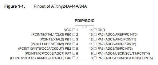
The first part is an overview of the functionalities and the pinout: it indicates basically which pin does what:
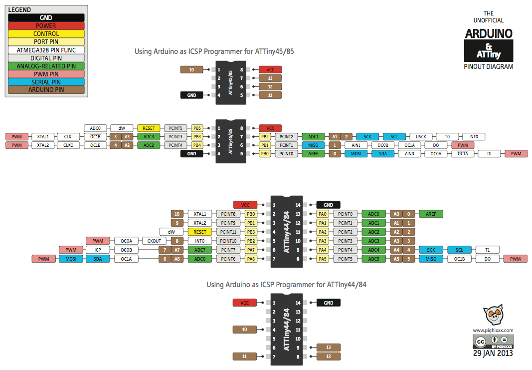
Guided by Denis’ doc, I found this pinout diagram, more clear and with more information.
This diagram is followed by pin description. At a first look, port A and B are mostly similar, they can be used as input or output, excepted that the port A is 8 bits and the port B is 4 bits. Both port are however deigned for special features, that are described further un the datasheet. The datasheet also includes a block diagram of the AVR architecture, that I found difficult to read.
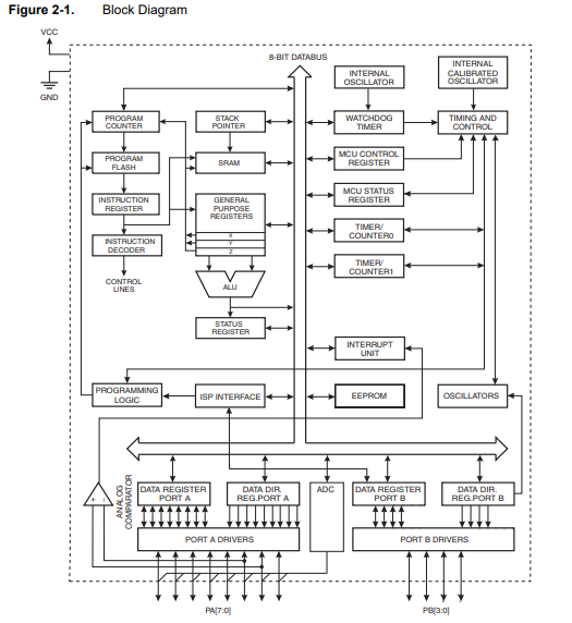
The architecture is then more precisely described, a section that I dind’t read very deeply.You can then read info on the memory, the clock, the power management and so on, and on the related registers that allow to configure them.
I/O ports
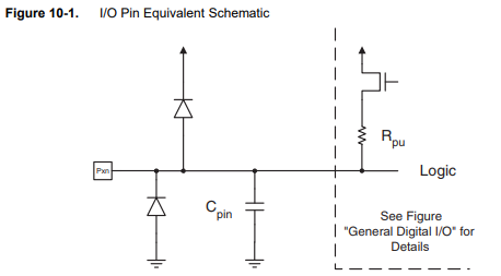
I read more carefully the section on the I/O ports, that I intend to use to light my LED on. They can all be configured as input and output, and include protections and pull-up resistors.
Some interesting content on the configuration and registers:
All registers and bit references in this section are written in general form. A lower case “x” represents the numbering letter for the port, and a lower case “n” represents the bit number
...
Each port pin consists of three register bits: DDxn, PORTxn, and PINxn. As shown in “Register
Description” on page 66, the DDxn bits are accessed at the DDRx I/O address, the PORTxn bits
at the PORTx I/O address, and the PINxn bits at the PINx I/O address.
The DDxn bit in the DDRx Register selects the direction of this pin. If DDxn is written logic one,
Pxn is configured as an output pin. If DDxn is written logic zero, Pxn is configured as an input
pin.
If PORTxn is written logic one when the pin is configured as an input pin, the pull-up resistor is
activated. To switch the pull-up resistor off, PORTxn has to be written logic zero or the pin has to
be configured as an output pin. The port pins are tri-stated when reset condition becomes active,
even if no clocks are running.
If PORTxn is written logic one when the pin is configured as an output pin, the port pin is driven
high (one). If PORTxn is written logic zero when the pin is configured as an output pin, the port
pin is driven low (zero).
...
Independent of the setting of Data Direction bit DDxn, the port pin can be read through the
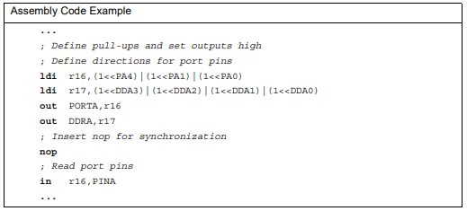
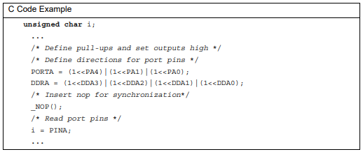
PINxn Register bitAnd some code examples:
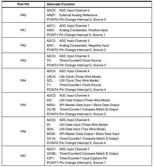
The following table describes the alternate specific functions of port A. The same can be found for port B. This is followed by a more precise description and by how to use the registers.
Many more possibilities are described in details. I just overlook at them, but this opens a lot of possibilities! The electrical characteristics are also precisely described in a dedicated section.
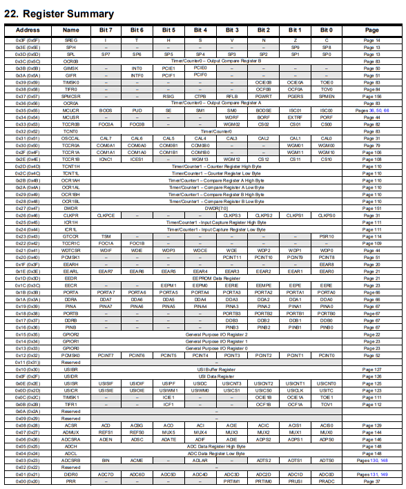
Summaries
The last two technical sections are the register and instructions summaries. In particular, the register summary is an overview table, containing links to the different parties of the doc. I think I will use this summary a lot…
Step 2: modifying tests programs
Getting a blink programs
Let’s start the real work! First, I will try to understand and adapt Nicolas’ polling customizable program which is already adapted from the course page. He also adapted the makefile on his page. Thank you Nico!
Modifying it
Before to have Nico’s file working, let’s make some modifications:
- On the Makefile. He used a ATtiny44, I have to change to ATtiny84.
PROJECT=$(patsubst %.c,%,$(wildcard *.c))
  SOURCES=$(PROJECT).c
  MMCU=attiny84
  AVRDUDE_PARTNO=t84
  F_CPU = 20000000
  L_FUSE=0x5E

  CFLAGS=-mmcu=$(MMCU) -Wall -Os -DF_CPU=$(F_CPU)

  $(PROJECT).hex: $(PROJECT).out
      avr-objcopy -O ihex $(PROJECT).out $(PROJECT).c.hex;\
      avr-size --mcu=$(MMCU) --format=avr $(PROJECT).out

  $(PROJECT).out: $(SOURCES)
      avr-gcc $(CFLAGS) -I./ -o $(PROJECT).out $(SOURCES)

  program-bsd: $(PROJECT).hex
      avrdude -p $(AVRDUDE_PARTNO) -c bsd -U flash:w:$(PROJECT).c.hex

  program-dasa: $(PROJECT).hex
      avrdude -p $(AVRDUDE_PARTNO) -P /dev/ttyUSB0 -c dasa -U flash:w:$(PROJECT).c.hex

  program-avrisp2: $(PROJECT).hex
      avrdude -p $(AVRDUDE_PARTNO) -P usb -c avrisp2 -U flash:w:$(PROJECT).c.hex

  program-avrisp2-fuses: $(PROJECT).hex
      avrdude -p $(AVRDUDE_PARTNO) -P usb -c avrisp2 -U lfuse:w:$(L_FUSE):m

  program-usbtiny: $(PROJECT).hex
      avrdude -p $(AVRDUDE_PARTNO) -P usb -c usbtiny -U flash:w:$(PROJECT).c.hex

  program-usbtiny-fuses: $(PROJECT).hex
      avrdude -p $(AVRDUDE_PARTNO) -P usb -c usbtiny -U lfuse:w:$(L_FUSE):m

  program-dragon: $(PROJECT).hex
      avrdude -p $(AVRDUDE_PARTNO) -P usb -c dragon_isp -U flash:w:$(PROJECT).c.hex

  program-ice: $(PROJECT).hex
      avrdude -p $(AVRDUDE_PARTNO) -P usb -c atmelice_isp -U flash:w:$(PROJECT).c.hex

  clean: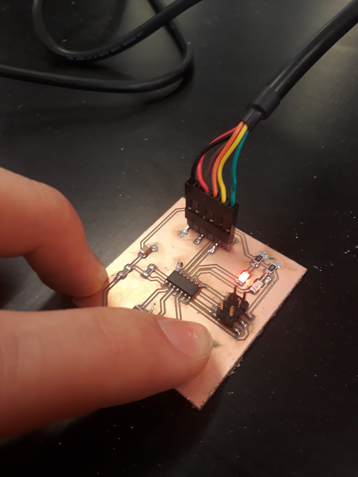
rm -f $(PROJECT).c.hex $(PROJECT).out- On the polling.c file. His test programs blink a LED when a button is pressed, and sends some text using the serial FTDI connection. I have to adapt it since I do not use the same pins for my LED and button. The code can be found on his page. I also read Neil’s original file to make sure to understand what Nico did. I have my LED (red) on PA2 and button on PB2 and pin out, I only change this in the file! Below is the debugged (see below) final code.
Let’s test it!
I use the my ISP programmer and the same setup and commands than in week 7 and directly, it works! (You can remove ISP connector)
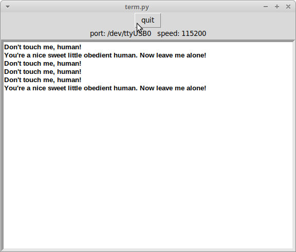
Problem: the serial communication does not work with Neil’s terminal used in week 7… I compare with Neil’s code and find a difference.. Nico changed the pin in and out (he explained why here)
Customizing it further
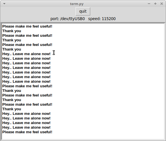
I want now to customize a little bit my code. I have two LEDs. I want the green one to blink when the button is just pressed, then the red one to replace it if it becomes longer. After several tries and a little bit of debugging, it works!
But my green led is burned… I checked and I have a 5V signal when supposed to, but the LED does not light on! I chose to not focus on this LED for the moment: I lack of time and the aim of this week is to program my board. This is just a “test board”, and I will have many more occasions on further assignment to add more LEDs.
The final c code can be downloaded here
Step 3: using Atmel Studio
Now that I succeeded to program my board on Linux and with my programmer, I want to find a solution for my windows laptop. To test this, I will use a very basic program that blink the LED when the button is pressed. I will use Atmel studio, a software that allows among other to create, build, test, and debug c programs for microcontrollers, and that includes tools for programming the microcontroller. Here is the loop of the little program I want to use:
while (1) { //loop forever (1 is equivalent to "true")
if bit_test(button_pins, button){
clear(led_port, led_pinR); //change the led status to not blink
}
else{
toggle(led_port, led_pinR); //change the led status to blink it
}
_delay_ms(1000); //wait a bit before going to the next loop (blinking visibily AND button debouncing)
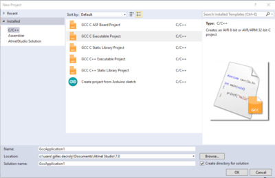
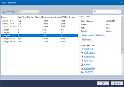
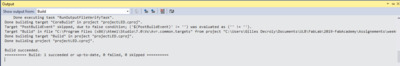
}I download the program and open it for the first time. The first step is to create a new executable project. You can then choose your device (here ATtiny84A), and a blank project is created. I play a little bit with the button, and it is quite intuitive. I copy and adapt my code, and then build the program. Atmel studio gives quite clear error or warning messages is something got wrong. If the build succeeded, I can compile my file, and it is ready to be uploaded on my microcontroller!
Uploading using fabISP
First, I will try to use my fabISP programmer. I found a great tutorial here on how to use Atmel studio with custom programmer.
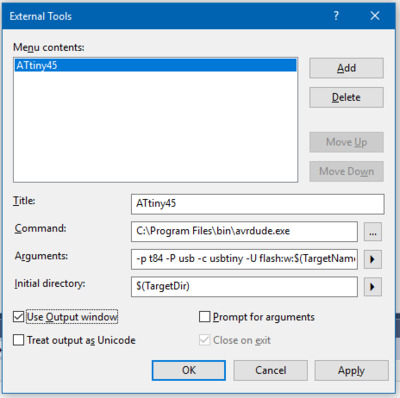
You must first define and setup your programmer in the menu tools -> extenal tools. After several tests and looking on forums and on the makefile, here is my final configuration. The command indicates the avrdude.exe file location in my laptop.
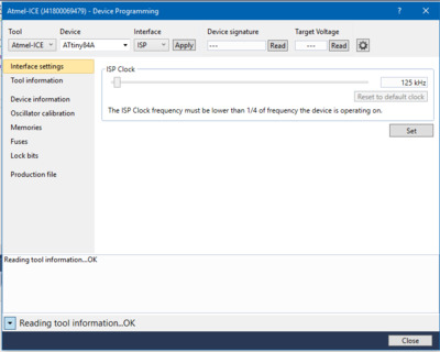
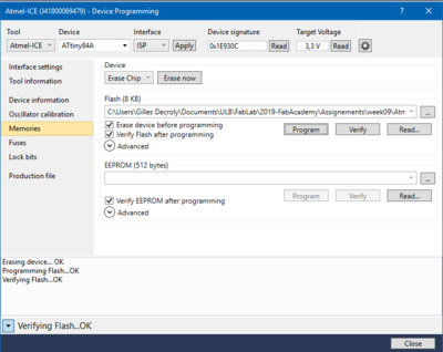
Then, just go in tools -> programming tool, and a nice interface appears. Select the newly defined programmer. To fuse the board, just use the button program in the fuses tab, and to flash it, use the program in the memory tab. Several other parameters can be setup from this window.
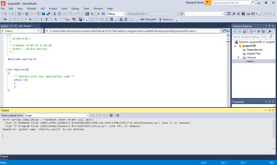
Problem: It does not work.. It could not find the USBtiny programmer… This is a similar problem that I experiences in week 5. Here is the error message: avrdude.exe: Error: Could not find USBtiny device (0x1781/0xc9f)
What I don’t understand is that the programmer is found in the peripheral. Anyway, I will try a backup solution with a commercial programmer.
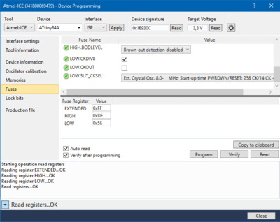
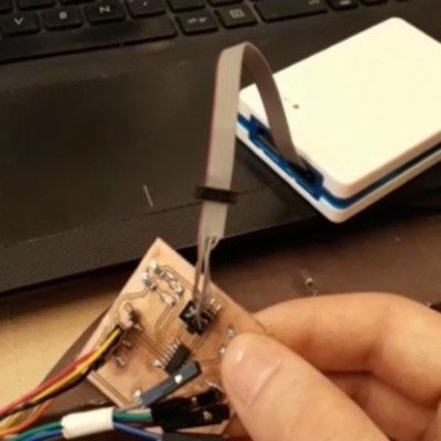
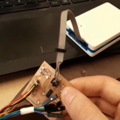
Uploading using Atmel-ICE
I am lucky enough to have a commercial Atmel ICE programmer. This time it is even more straightforward. The same programming interface can be used without having to define the tool. Be also carful in the pinout, that must be checked from the datasheet.
At the first time it works, but there seem to be a clock problem. After several checks (and increasing the delay between each toggle of the LED value to 10 seconds), I notice that the clocks (and consequently the LED) goes around 10 times too fast!
Solution 1: My first intuition is that this is related to the fuses settings in the programming interface of Atmel. However, my fuse is correctly set to 0x5E (as in the working test on the linux machine, and as indicated in the datasheet). I also checked in section 19.2 of the datasheet: the high and extended fuses are on default values (good), this should be ok!
Conclusion: the problem doesn’t seem to be here.
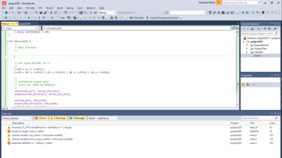
Solution 2: Reading the makefile, I notice that the frequency is a parameter given in the makefile and passed in arguments when programming the chip using avrdude on linux. As proposed in several forums, I then try to redefine F_CPU (the frequency of the CPU) to 20 Mhz, by adding #define F_CPU 20000000UL on first line of the code… And it works! (this is not very clear on the image, but the LED blinks!)
The final c code can be downloaded here
Good! I have now a way to program my boards using my fab ISP on linux, and another one with my windows 10 laptop! I’ll have other occasions to make funnier programs but I does not feel lost in the programming part!
Update week 14
In the following weeks, I also used the Arduino IDE, both with a programmer and with serial communication and a bootloader. Many choices for prgramming!
Step 3: group assignment
We used several workflows to get our board programmed, let’s compare them!
Languages:
c: we all programmed our microcontrollers in cassembler: Axel also tried assembler, just for fun!
programming in c seems to be clearly the easy way here. However, it still remain very general, and allows to keep a good control and what you want your chip to do!
Programming environment, compiler, and programmer:
Any text editor,avrdude, and afabISPon Linux: Gilles and Christophe used this solution. It requires a makefile to tell arvdude how to program the chip.Any text editor,WinAVR, and afabISPon Windows 7: Greta and Axel tested this solution, similar to the first on but on Windows 7.Arduino IDEand anArduinoon Windows: Greta and Amy tried tris solution.Atmel studioand afabISPon Windows:Gilles tried this solution, but did not succeed.Atmel studioand aAtmel commercial programmeron Windows: Greta, Amy and Gilles tried this.
Using avrdude is very efficient and was a good solution, but you need Linux. WinAVR is similar but only works on windows 7. If you want to program using windows (without becoming crazy), using commercial solutions will be required… It has the drawback to be commercial, but depending on the solution, you will have more possibilities in term of debugging and reading the chip than avrdude or winAVR!