Electronics design
Objectives of the week
- Group assignment
- Use the test equipment in your lab to observe the operation of a microcontroller circuit board
- Individual assignment
- redraw the echo hello-world board, add (at least) a button and LED (with current-limiting resistor), check the design rules, make it, and test it.
- extra credit: simulate its operation
I do not feel totally lost this week, but it will be a challenging one! Not the most creative on but I will learn many new tools... Let's do it!
What I did
- Discovered and used KiCAD
- Made my customized PCB and tested it
What I learned
- To keep calm
- To design PCBs
- To play with electronics components traces
If I had the time to go further...
- I would have programmed and tested my board with custom code
- I would have my programmer working
Files and resources
Step 1: group assignments
The minimum test equipment for a electronics lab consists generally in :
- regulated power supply
- low frequency generator
- oscilloscope
- logical analyzer
- multimeter
Resources available @FablabULB:
- HP 54602B oscilloscope, with HP 10071A 10:1 probes (attenuation ratio of 10:1: this means that the signal displayed on the screen is reduced by a factor 10)
- HAMEG Digital multimeter HM8011-3
As the lab is not completely equipped yet, we decided to go for simple measurements:
- Continuity check: with simple multimeter, we can check if there are shorts and no-contact on the nets (unpowered system).
- Diode check: with a simple multimeter, we can check if the diodes (Leds, Zener, signal, etc..) are polarized correctly (unpowered system)
- Voltage measurements: DC voltages at given points are easy to measure with a simple multimeter, AC voltages and time-varying signals are best measured with a oscilloscope…(powered system)
- Current measurements: more difficult to measure, as the loop where it flows needs to be opened....
We measure the signal on VCC pin: (either on the multimeter or the oscilloscope)
We measure the signal on the blinking led :
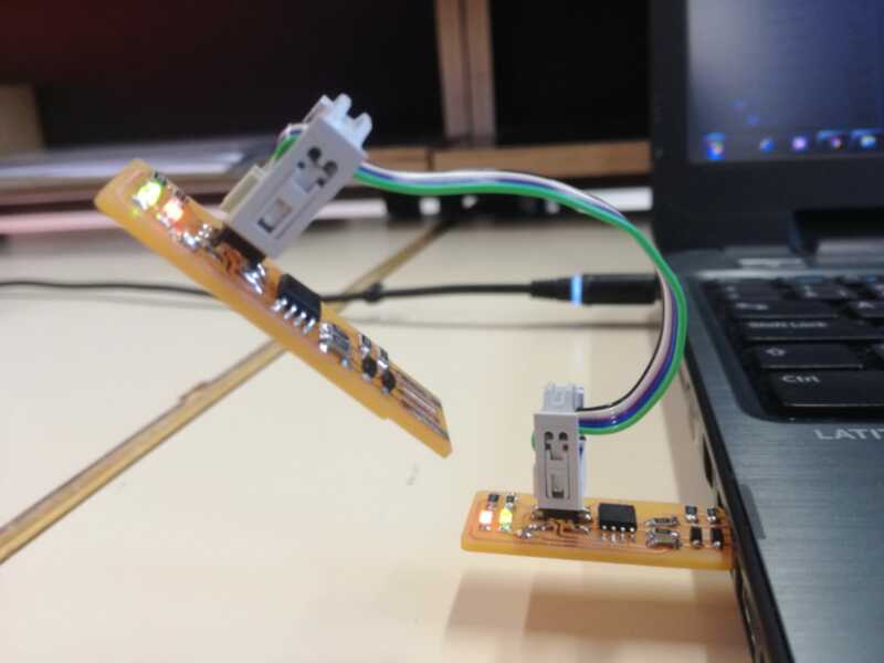 |
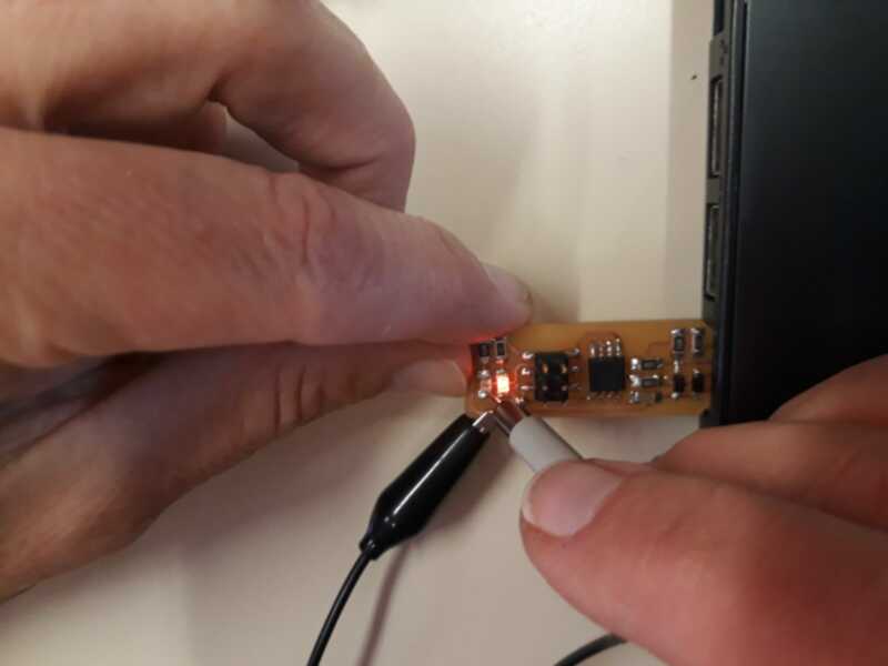 |
|---|---|
| programming | measuring |
To see the variations, we best use the oscilloscope:
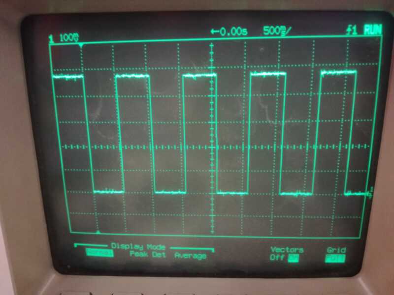
We recognize the 1sec period (scale is 500msec/square), and the attenuation factor of 10 (scale is 100mV/square)
Step 2: designing the board
Tools and design rules
I was hesitating between Eagle and KiCAD, I read this comparison. Since both seem very similar, I choose to use KiCAD, mainly because it is open-source and because of its 3D render tool. Neil’s tutorial will be useful to discover KiCAD.
Redrawing the board schematics
Here is the board to redraw:

I open KiCAD for the first time. I create new project and go the Schematics editor.
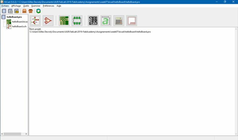
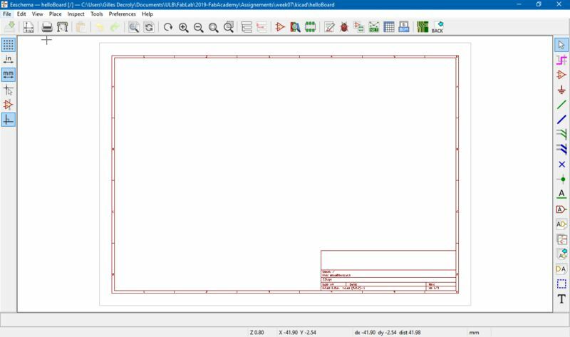
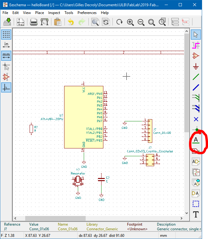
This is not very intuitive, but there are good keyboard shortcuts:
| key | action |
|---|---|
m |
move the component with the mouse (click to release) |
g |
grab the component + the connected wire with the mouse (click to release) |
r |
Rotate of 90° |
w |
place a wire |
a |
Insert a component |
e |
Component properties |
We can place components from libraries. We can search by categories or using keywords.
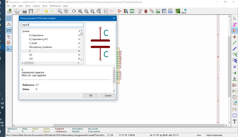
We have the ATMEL Tiny84A-SSU in the fab lab. I found it in the schematics library MCU_microchip_ATmega > ATtiny84-PU. It is the same chip that ATtiny44 with more memory. FOr the other components, I use basic resistor, resonator, pin headers and capacitor. I will manage the traces. I only learn when I am finished that there s a custom library for KiCAD containing all fab academy components.. Next step: placing the wires. I use dedicated elements for ground (GND) and the 5V power (VCC). It avoids to use too much wires. It is also possible to use labels. Be carefull to place them at the extremity of the wires. Two wires with the same label are electrically connected.
Customizing the hello-world board
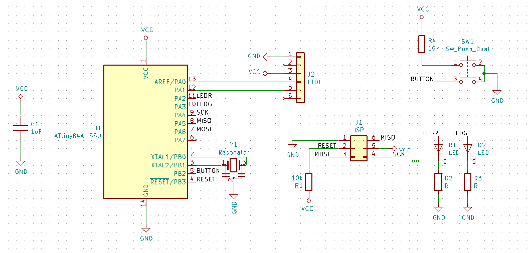
I will add 2 LEDs and a push button, just as proposed by Neil. We have this button in the lab. I don’t find the correct symbol, so I use another one with 4 pins, and I manually “correct” the connections, to be sure not to forget it. I check the datasheet to know where to connect my LED and button. The B pins are bidirectional, i.e. can be put as input or output. I will use the pin PB2 as input for my button. They also have integrated pull-up resistor, but I also add an other pull-up resistor externally to explicit and demonstrate how it works. I allows to ensure the voltage to remain at 5V as long as the button is not pushed. The pins A are also bidirectional. I will use the pins PA2 and PA3 for the LEDs. I also assign values and annotations to my components.
This how my final schematics looks like (after many iterations with the PCB layout).
Drawing the PCB
Once you have the schematics, just follow the process:
Of course this will never be as linear, but it is always possible to correct something (a trace, connections in the schematics, …) and update the PCB.
Associate the footprints
First, I need to assign a footprint to the generic components. Here a the component I will use.
- ATtiny84A-SSU
- Resonator 20 MHz
- R1/R2 - 10k
- R2/R3 - 150
- C1 - 1uF
- Red LED
- Green LED
- Connector ISP
- Connector FTDI
- Push button
This tuto shows how to do it. An important thing is to filter components when checking in the libraries. I check for the packages in the datasheet. Most components (resistors, LEDS, …) are 1206 (3216 metric). Good tools of KiCAD are the footprint view and the 3D view of the components!
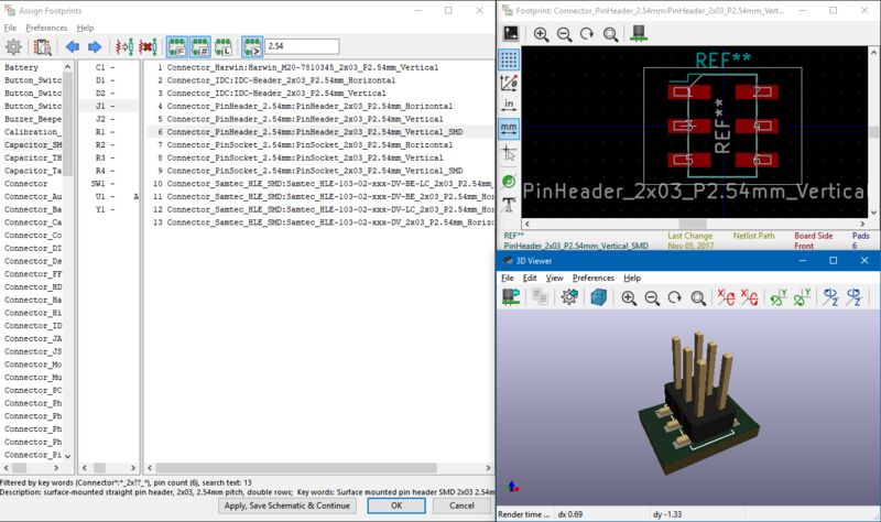
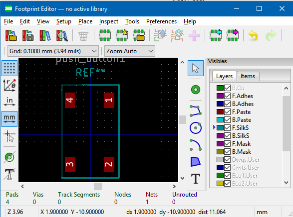
I also have to create my custom footprint for the push button, since it is not in the basic libraries. Here is a tuto on how to do it. I use first the values of the datasheet, but I’ll have to adapt this later… Finally, here is a tuto on how to save the new footprint.
Generate the netlist
Simply click the buttons and save it in your folder.
Make the layout
I open a NewPCB window, and open the netlist. The components footprints will appear in the window, with indications on the connections to trace.
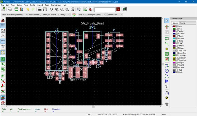
The same shortcuts than in the schematics view can be used. Note that you can update your schematics and then PCB by using the Tools menu.
Be careful on pin numbering! Especially in my case, the button pin numbering is custom. The design rules must be defined before to trace the connections. They can be set in the Setup -> design rules menu. They are based on the results of week 5:
| Track width | Clearance |
|---|---|
| 0.4 mm | 0.4 mm |
The rest is fun and making the connections.. pretty intuitive! I use only one Layer. As a last thing, I also add a ground plane. To do so, you must use the fillet zone tool.
Before milling the PCB, as a first test: I print a svg file on paper and place components.
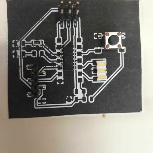
some adjustment are required:
- Button traces too large
- FTDI header too big for the Traces
- Wrong packaging for the ATtiny44The traces for the resonator are too spaced.
- the 1206 SMD component traces are good.. ouf!
I will also increase the space with the ground plane to avoid shortcuts.
I go back in the footprint editor and make my custom traces. I also got confused by ATtiny84 and ATtiny84A that we have.
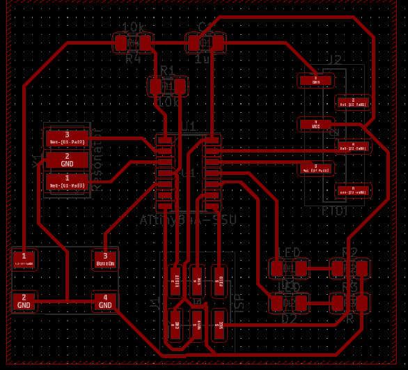
Here is the final PCB layout I obtain after all the tests and iterations:
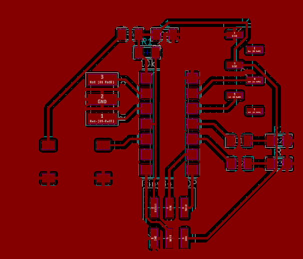
The source files can be downloaded here
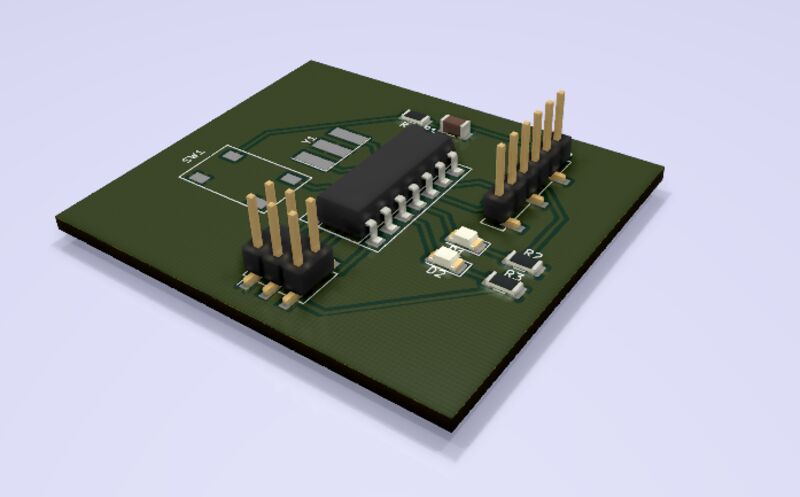
Rendering the board in 3D
Rendering the board is really straightforward with View -> 3D viewer :
Step 3: making the board
Milling the PCB
After several tries, I followed this tuto to export the PCB in gerber format. I used the Bantam milling machine as in week05. This is the result of the first try:
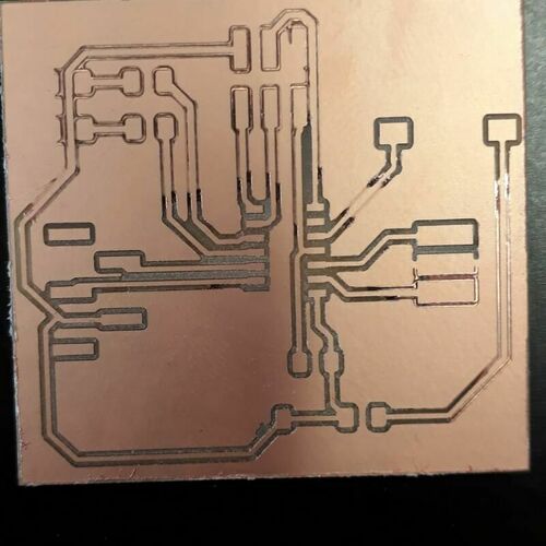
Problem: the traces are not correctly cut. The PCB was not perfectly flat and some engraving are not complete…
Solution: Increase the cut depth from 0.15 to 0.2 mm. But the milling times becomes very long (about 2 hours), so we create a new tool settings with a deeper cut, in the File-> tool library menu. This allows to go from 2 hours to 45 minutes!
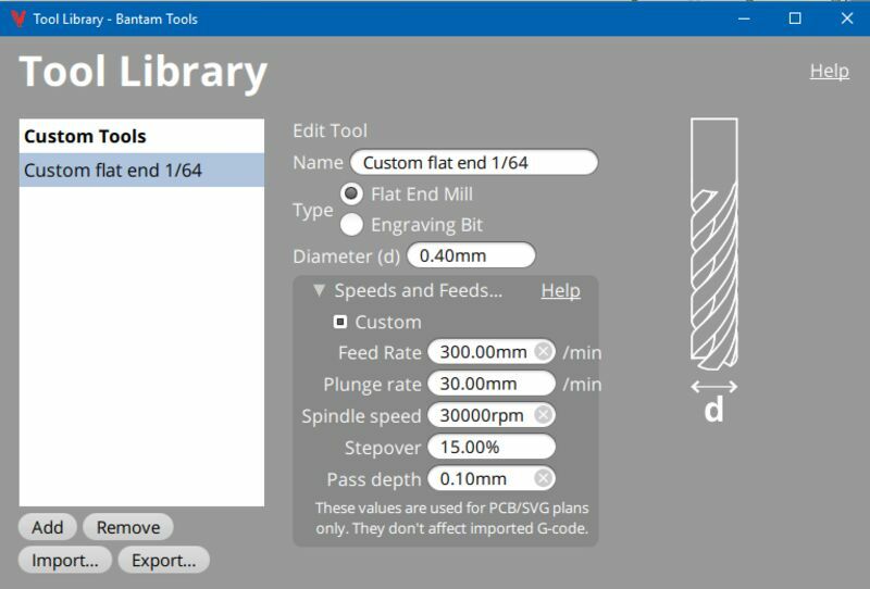
Here are the milling parameter used for the custom tool. Note that the speed and the pass depth can easily be increased to make it even faster.
| Parameter | Value |
|---|---|
| Feed rate | 300 mm/min |
| Plunge rate | 30 mm/min |
| Spindle speed | 30000 rpm |
| Stepover | 15% |
| pass depth | 0.1 mm |
The second try is better!
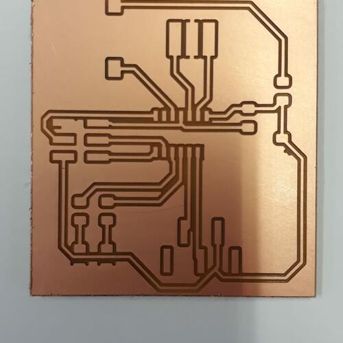
I also test the board, making sure there is no shortcut with the ground.
Welding the components
I used the same materials and methods than in week 5.
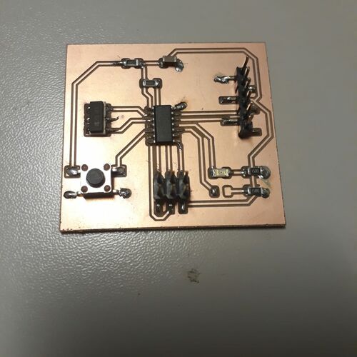
Step 4: Testing the board
Let’s test the board! To do this, I connect my programmer to the Linux machine and to my board using the ISP connector. I also need to power my board and to make it able to communicate with the Linux machine, so I connect them with the FTDI connector.
To use Neil’s Hello world testing program, I need a folder with the 3 following files: hello.ftdi.44.echo.c, hello.ftdi.44.echo.c.make, and term.py (for python terminal used for the FTDI communication).
Failed try - using my programmer
For the first try, I use the programmer that I made in week 5.
$ make -f hello.ftdi.44.echo.c.make
make: Warning: File 'hello.ftdi.44.echo.c.make' has modification time 35473 s in the future
avr-gcc -mmcu=attiny44 -Wall -Os -DF_CPU=20000000 -I./ -o hello.ftdi.44.echo.out hello.ftdi.44.echo.c
avr-objcopy -O ihex hello.ftdi.44.echo.out hello.ftdi.44.echo.c.hex;\
avr-size --mcu=attiny44 --format=avr hello.ftdi.44.echo.out
AVR Memory Usage
----------------
Device: attiny44

Program:     758 bytes (18.5% Full)
(.text + .data + .bootloader)

Data:         64 bytes (25.0% Full)
(.data + .bss + .noinit)
I have a warning that I already saw Clock skew detected. Your build may be incomplete.. Let’s continue anyway and see what happens!
$ sudo make -f hello.ftdi.44.echo.c.make program-usbtiny-fuses
make: Warning: File 'hello.ftdi.44.echo.c.make' has modification time 34111 s in the future
avr-gcc -mmcu=attiny44 -Wall -Os -DF_CPU=20000000 -I./ -o hello.ftdi.44.echo.out hello.ftdi.44.echo.c
avr-objcopy -O ihex hello.ftdi.44.echo.out hello.ftdi.44.echo.c.hex;\
avr-size --mcu=attiny44 --format=avr hello.ftdi.44.echo.out
AVR Memory Usage
----------------
Device: attiny44

Program:     758 bytes (18.5% Full)
(.text + .data + .bootloader)

Data:         64 bytes (25.0% Full)
(.data + .bss + .noinit)


avrdude -p t44 -P usb -c usbtiny -U lfuse:w:0x5E:m
avrdude: Error: Could not find USBtiny device (0x1781/0xc9f)

avrdude done.  Thank you.

hello.ftdi.44.echo.c.make:31: recipe for target 'program-usbtiny-fuses' failed
make: *** [program-usbtiny-fuses] Error 1
It didn’t work… I will need to correct the problem! In the meanwhile, let’s try with Adrien’s programmer.
Failed try - using Adrien’s programmer
$ sudo make -f hello.ftdi.44.echo.c.make program-usbtiny-fuses
make: Warning: File 'hello.ftdi.44.echo.c.make' has modification time 33782 s in the future
avr-gcc -mmcu=attiny44 -Wall -Os -DF_CPU=20000000 -I./ -o hello.ftdi.44.echo.out hello.ftdi.44.echo.c
avr-objcopy -O ihex hello.ftdi.44.echo.out hello.ftdi.44.echo.c.hex;\
avr-size --mcu=attiny44 --format=avr hello.ftdi.44.echo.out
AVR Memory Usage
----------------
Device: attiny44

Program:     758 bytes (18.5% Full)
(.text + .data + .bootloader)

Data:         64 bytes (25.0% Full)
(.data + .bss + .noinit)


avrdude -p t44 -P usb -c usbtiny -U lfuse:w:0x5E:m

avrdude: AVR device initialized and ready to accept instructions

Reading | ################################################## | 100% 0.01s

avrdude: Device signature = 0x1e930c (probably t84)
avrdude: Expected signature for ATtiny44 is 1E 92 07
         Double check chip, or use -F to override this check.

avrdude done.  Thank you.

hello.ftdi.44.echo.c.make:31: recipe for target 'program-usbtiny-fuses' failed
make: *** [program-usbtiny-fuses] Error 1
It already goes further than with my programmer, but I have a new fail. This time the indications are more clear: the make file expects an ATtiny44, and we used an ATtiny84.
Succeed try - using Adrien’s programmer and changing the make file
Let’s modify the hello.ftdi.44.echo.c.make file! ** Here is the new version of the file:
PROJECT=hello.ftdi.44.echo
SOURCES=$(PROJECT).c
MMCU=attiny84
F_CPU = 20000000

CFLAGS=-mmcu=$(MMCU) -Wall -Os -DF_CPU=$(F_CPU)

$(PROJECT).hex: $(PROJECT).out
    avr-objcopy -O ihex $(PROJECT).out $(PROJECT).c.hex;\
    avr-size --mcu=$(MMCU) --format=avr $(PROJECT).out

$(PROJECT).out: $(SOURCES)
    avr-gcc $(CFLAGS) -I./ -o $(PROJECT).out $(SOURCES)

program-bsd: $(PROJECT).hex
    avrdude -p t84 -c bsd -U flash:w:$(PROJECT).c.hex

program-dasa: $(PROJECT).hex
    avrdude -p t84 -P /dev/ttyUSB0 -c dasa -U flash:w:$(PROJECT).c.hex

program-avrisp2: $(PROJECT).hex
    avrdude -p t84 -P usb -c avrisp2 -U flash:w:$(PROJECT).c.hex

program-avrisp2-fuses: $(PROJECT).hex
    avrdude -p t84 -P usb -c avrisp2 -U lfuse:w:0x5E:m

program-usbtiny: $(PROJECT).hex
    avrdude -p t84 -P usb -c usbtiny -U flash:w:$(PROJECT).c.hex

program-usbtiny-fuses: $(PROJECT).hex
    avrdude -p t84 -P usb -c usbtiny -U lfuse:w:0x5E:m

program-dragon: $(PROJECT).hex
    avrdude -p t84 -P usb -c dragon_isp -U flash:w:$(PROJECT).c.hex

program-ice: $(PROJECT).hex
    avrdude -p t84 -P usb -c atmelice_isp -U flash:w:$(PROJECT).c.hex
And let’s start again with in the terminal:
2$ make -f hello.ftdi.44.echo.c.make
make: Warning: File 'hello.ftdi.44.echo.c' has modification time 33433 s in the future
avr-gcc -mmcu=attiny84 -Wall -Os -DF_CPU=20000000 -I./ -o hello.ftdi.44.echo.out hello.ftdi.44.echo.c
avr-objcopy -O ihex hello.ftdi.44.echo.out hello.ftdi.44.echo.c.hex;\
avr-size --mcu=attiny84 --format=avr hello.ftdi.44.echo.out
AVR Memory Usage
----------------
Device: attiny84

Program:     758 bytes (9.3% Full)
(.text + .data + .bootloader)

Data:         64 bytes (12.5% Full)
(.data + .bss + .noinit)


make: warning:  Clock skew detected.  Your build may be incomplete.
$ sudo make -f hello.ftdi.44.echo.c.make program-usbtiny-fuses
make: Warning: File 'hello.ftdi.44.echo.c' has modification time 33397 s in the future
avr-gcc -mmcu=attiny84 -Wall -Os -DF_CPU=20000000 -I./ -o hello.ftdi.44.echo.out hello.ftdi.44.echo.c
avr-objcopy -O ihex hello.ftdi.44.echo.out hello.ftdi.44.echo.c.hex;\
avr-size --mcu=attiny84 --format=avr hello.ftdi.44.echo.out
AVR Memory Usage
----------------
Device: attiny84
Program: 758 bytes (9.3% Full)
(.text + .data + .bootloader)
Data: 64 bytes (12.5% Full)
(.data + .bss + .noinit)
avrdude -p t84 -P usb -c usbtiny -U lfuse:w:0x5E:m
avrdude: AVR device initialized and ready to accept instructions
Reading | ################################################## | 100% 0.01s
avrdude: Device signature = 0x1e930c (probably t84)
avrdude: reading input file "0x5E"
avrdude: writing lfuse (1 bytes):
Writing | ################################################## | 100% 0.02s
avrdude: 1 bytes of lfuse written
avrdude: verifying lfuse memory against 0x5E:
avrdude: load data lfuse data from input file 0x5E:
avrdude: input file 0x5E contains 1 bytes
avrdude: reading on-chip lfuse data:
Reading | ################################################## | 100% 0.00s
avrdude: verifying ...
avrdude: 1 bytes of lfuse verified
avrdude: safemode: Fuses OK (E:FF, H:DF, L:5E)
avrdude done. Thank you.
make: warning: Clock skew detected. Your build may be incomplete.$ sudo make -f hello.ftdi.44.echo.c.make program-usbtiny
make: Warning: File 'hello.ftdi.44.echo.c' has modification time 33331 s in the future
avr-gcc -mmcu=attiny84 -Wall -Os -DF_CPU=20000000 -I./ -o hello.ftdi.44.echo.out hello.ftdi.44.echo.c
avr-objcopy -O ihex hello.ftdi.44.echo.out hello.ftdi.44.echo.c.hex;\
avr-size --mcu=attiny84 --format=avr hello.ftdi.44.echo.out
AVR Memory Usage
----------------
Device: attiny84
Program: 758 bytes (9.3% Full)
(.text + .data + .bootloader)
Data: 64 bytes (12.5% Full)
(.data + .bss + .noinit)
avrdude -p t84 -P usb -c usbtiny -U flash:w:hello.ftdi.44.echo.c.hex
avrdude: AVR device initialized and ready to accept instructions
Reading | ################################################## | 100% 0.01s
avrdude: Device signature = 0x1e930c (probably t84)
avrdude: NOTE: "flash" memory has been specified, an erase cycle will be performed
To disable this feature, specify the -D option.
avrdude: erasing chip
avrdude: reading input file "hello.ftdi.44.echo.c.hex"
avrdude: input file hello.ftdi.44.echo.c.hex auto detected as Intel Hex
avrdude: writing flash (758 bytes):
Writing | ################################################## | 100% 0.42s
avrdude: 758 bytes of flash written
avrdude: verifying flash memory against hello.ftdi.44.echo.c.hex:
avrdude: load data flash data from input file hello.ftdi.44.echo.c.hex:
avrdude: input file hello.ftdi.44.echo.c.hex auto detected as Intel Hex
avrdude: input file hello.ftdi.44.echo.c.hex contains 758 bytes
avrdude: reading on-chip flash data:
Reading | ################################################## | 100% 0.61s
avrdude: verifying ...
avrdude: 758 bytes of flash verified
avrdude: safemode: Fuses OK (E:FF, H:DF, L:5E)
avrdude done. Thank you.
make: warning: Clock skew detected. Your build may be incomplete.It seems to have worked! Let’s open the terminal with the command:
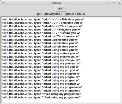
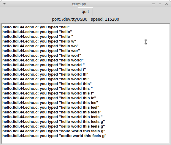
$ python term.py /dev/ttyUSB0 115200Tadaa! Here is the result: it is working!
Udpate week 9 - Suceeded try with my programmer!
I wanted to do the rest of the fab academy with a working programmer! So I debugged it an had finally my programmer working during week 9! The problem? A bad connection between the headers of my board and the FTDI cable… After the troubleshooting described in week 5, I finally was able to program my hello world board with my USBtiny programmer!
