Networking and communications
Objectives of the week
- Individual assignment
- Design, build, and connect wired or wireless node(s) with network or bus addresses
- Group assignment
- Send a message between two projects
This week is interesting! I have almost no knowledge in networking and communications. I will try to use this week's assignment to add a LCD display to my final project!
What I did
- Programmed my Satshakit as an Arduino
- Tested I²C communication betwen 2 Satshakits
- Communicated with an LCD using I²C
What I learned
- How does I²C works!
If I had the time to go further...
- I would have tested more communication protocols
- I would have been further in the understanding of how to communicate with the LCD in I²C
Files and resources
Step 1: Finding some inspiration
As often, I begin my week by checking Denis’ documentation to find some inspiration.
I have not a lot of experience in networking and communication, so I would like to learn I²C, which seems accessible, not using too much pins, and a good example of communication protocol. As Denis, I anticipated and made a satshakit board in week 11, that I will use for this week.
I also want this week assignment to be useful for my final project, so my objective for this week is to communicate with a LCD display. After searching a lot through the internet and changing many times of mind about what I’ll do this week, here are the main possibilities that I identified:
- Make a second board with a ATMega microcontroller based on Neil’s LCD program [http://academy.cba.mit.edu/classes/output_devices/index.html], as made by this other student, but it does not seems to be the most elegant and seems to me like bringing in an elephant to kill a mouse.
- Use a RGB LCD shield that I already have in my lab. It can be interfaced through I²C thanks to this I²C to serial expander, but its libraries only work for arduino, and I am not sure to be able to have it work…
- Use another interfacing chip, as documented in this tutorial. I have here two choices:
- Even making the LCD-interfacing chip PCB myself
- Even by a PCB kit using this interfacing chip
Step 2: Understanding and testing I²C between 2 chips
First, some words about I²C. I2C is a serial bi-directionnel communication protocol using only two wires. In the AVR world, due to patent restriction, it is called TWI. In this protocol, a master communicates with a slave. The two wires are for the data (SDA) and for the clock (SCL). Basically, the master commands all the communication (sets the clock, initiate and terminates the communication). Multiple slaves can be used.
In my case, I will use my satshakit board made in week 11 as master, and a second Satshakit as slave.
First, let’s use my satshakit as Arduino
In the previous electronics weeks and for my final project, I used the avr-gcc toolchain or Atmel studio to program my boards. Moving forward, I found many Arduino only compatible libraries, and seeing the code complexity increase, I decided to use the Arduino IDE (that can be use both on my Windows laptop or on a Linux machine!). I have there two solutions: either use the Arduino IDE and all the libraries and still program my board using a programmer, even burn a bootloader on the ATmega328P and use a simple serial communication to program it.
First try (failed): Arduino IDE + fabISP programmer
I want to upload an empty sketch, just to test the toolchain.
In the arduino IDE, I have first to set the board and programmer in the tools menu. I set the board as lilypad arduino and the processor to atmega328p. As programmer, I set USBtinyIS. Finally, in the sketch menu, I choose upload using programmer.
Unfortunately, it does not work. My computer does not find my FabISP. In the peripherals menu, it indicates fabISP, and not USBtiny¨ as expected… After verification, it works perfeclty on Christoph’s laptop, which is the same then mine…
Second try (succeeded): Adruino IDE + Adruino as ISP
For this second try, I followed this tuto and Denis’ doc. The first step is to upload the example Arduino sketch ArduinoISP. Then, making sure twice of my connections, and setting Arduino as ISP as programmer, I can try to upload my empty sketch.

It works!
Third try (succeeded): Arduino IDE + bootloader
If I want to use the Arduino IDE, let’s do it the simple way!
To upload the bootloader and be able to program my board with a simple serial communication, I have first to use the same setup than for the second try, and click on the burn bootloader button in the toole menu.


Fast and simple! Let’s test the programation. I use this time the example blink code.
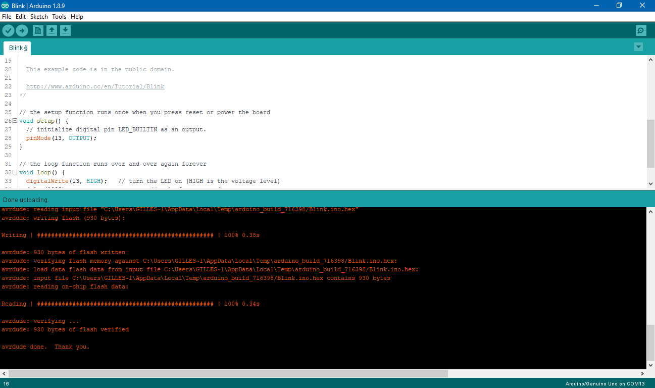
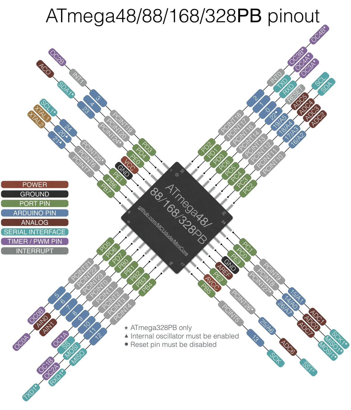
It works!! I have a new and simple way to program my board. But be careful! Arduino has it own numbering for the pinout of the ATMega328P:
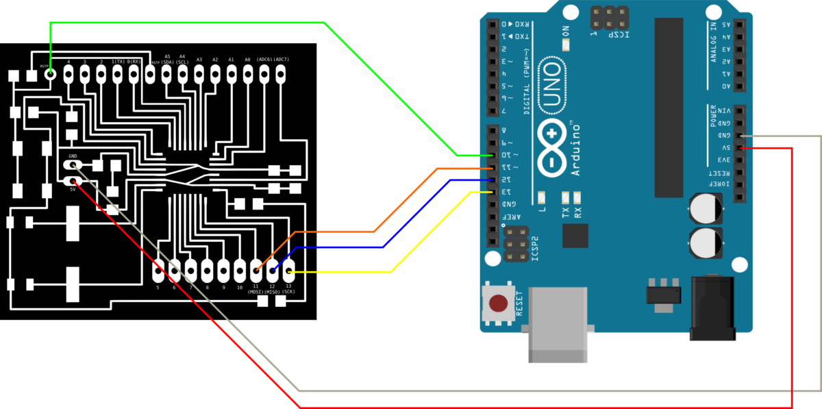
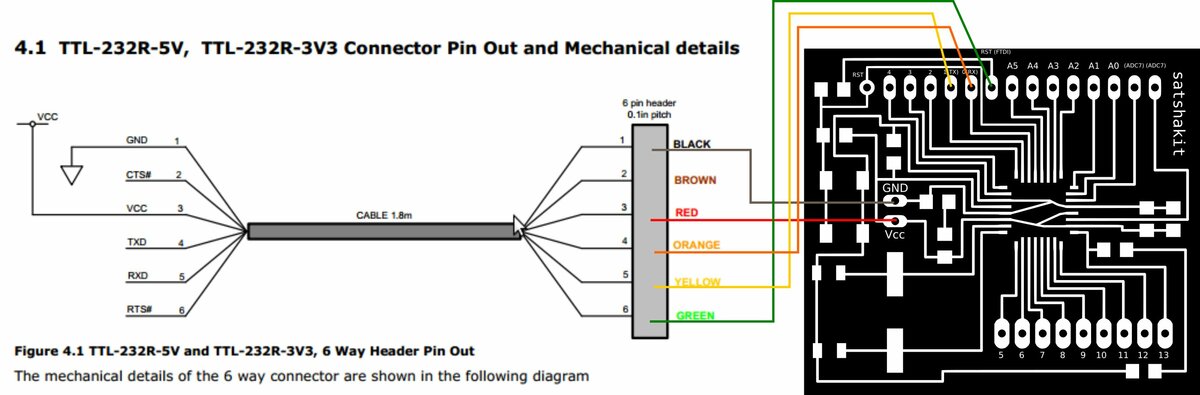
And here is the connection to the FTDI cable:
Let’s test the communication
To test the communication, I will use the board that I made in wek 11. Christophe made the same board, so we’ll do it together.
As Denis did, we followed this excellent Arduino tutorial. It uses the Wire library that includes ready to use functions.
To use I²C, we must define a master and a slave. Here is the code to upload to the aster board:
// Wire Master Writer
// by Nicholas Zambetti <http://www.zambetti.com>

// Demonstrates use of the Wire library
// Writes data to an I2C/TWI slave device
// Refer to the "Wire Slave Receiver" example for use with this

// Created 29 March 2006

// This example code is in the public domain.


#include <Wire.h>

void setup() {
  Wire.begin(); // join i2c bus (address optional for master)
}

byte x = 0;

void loop() {
  Wire.beginTransmission(8); // transmit to device #8
  Wire.write("x is ");        // sends five bytes
  Wire.write(x);              // sends one byte
  Wire.endTransmission();    // stop transmitting

  x++;
  delay(500);
}
And here is the board to upload to the slave board:
// Wire Slave Receiver
// by Nicholas Zambetti <http://www.zambetti.com>
// Demonstrates use of the Wire library
// Receives data as an I2C/TWI slave device
// Refer to the "Wire Master Writer" example for use with this
// Created 29 March 2006
// This example code is in the public domain.
#include <Wire.h>
void setup() {
Wire.begin(8); // join i2c bus with address #8
Wire.onReceive(receiveEvent); // register event
Serial.begin(9600); // start serial for output
}
void loop() {
delay(100);
}
// function that executes whenever data is received from master
// this function is registered as an event, see setup()
void receiveEvent(int howMany) {
while (1 < Wire.available()) { // loop through all but the last
char c = Wire.read(); // receive byte as a character
Serial.print(c); // print the character
}
int x = Wire.read(); // receive byte as an integer
Serial.println(x); // print the integer
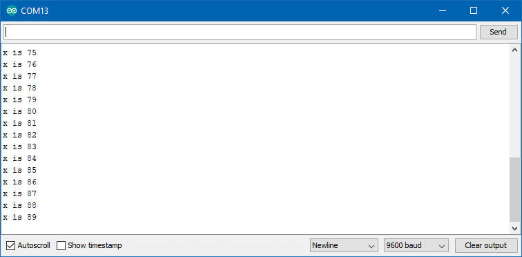
}The connections must also be adapted to the satshakit. On the ATMega328P (as for any microcontroller), the SCL and SDA pins are predefined: we have no choice here! The principle of the little test program is the following: the master board send data (basically a counter incremented each 500 ms) to the slave board, and the slave board use the serial communication with the laptop to print the data.
An important line in the code is the address line! The slave ha an address which is defined (here 8), and the master speaks to the slave number 8! We can also see that the master starts and ends each message. On the slave side, the board is setup to be ready to receive messages, and the function receiveEvents is predefined to understand and process those messages.
Here is the setup that we used:
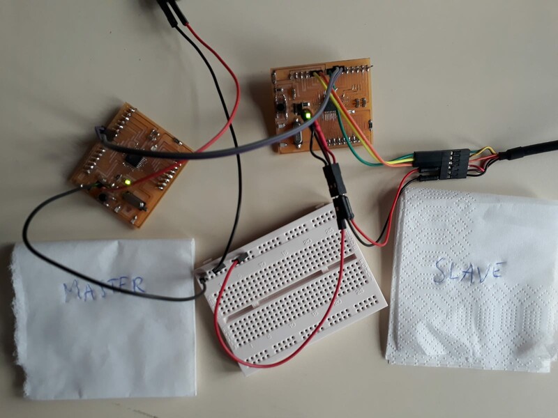
And it works!
Step 3: Using a LCD with I²C
I have a RGB LCD shield usused in may lab, so let’s use it as display! Here is an easy tutorial on how to use it. Basically, it includes a chip making an interface for the communication to the LCD. It recieves I²C messages from the board, and communicates in serial on 7 pins with the LCD!
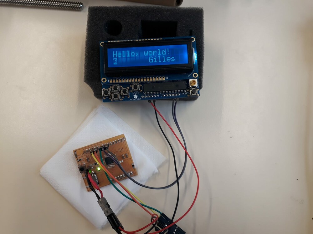
Fortunately, this shield comes with a library, that can be found on the tutorial page! The example code is very simple! It is however quite a black box concerning the I2C protocol. I modified it to write my name on the display:
/*********************

Example code for the Adafruit RGB Character LCD Shield and Library

This code displays text on the shield, and also reads the buttons on the keypad.
When a button is pressed, the backlight changes color.

**********************/

// include the library code:
#include <Wire.h>
#include <Adafruit_RGBLCDShield.h>
#include <utility/Adafruit_MCP23017.h>


// The shield uses the I2C SCL and SDA pins. On classic Arduinos
// this is Analog 4 and 5 so you can't use those for analogRead() anymore
// However, you can connect other I2C sensors to the I2C bus and share
// the I2C bus.
Adafruit_RGBLCDShield lcd = Adafruit_RGBLCDShield();

// These #defines make it easy to set the backlight color
#define RED 0x1
#define YELLOW 0x3
#define GREEN 0x2
#define TEAL 0x6
#define BLUE 0x4
#define VIOLET 0x5
#define WHITE 0x7

void setup() {
  // Debugging output
  Serial.begin(9600);
  // set up the LCD's number of columns and rows:
  lcd.begin(16, 2);

  // Print a message to the LCD. We track how long it takes since
  // this library has been optimized a bit and we're proud of it :)
  int time = millis();
  lcd.print("Hello, world!");
  lcd.setCursor(8,1);
  lcd.print("Gilles");
  time = millis() - time;
  Serial.print("Took "); Serial.print(time); Serial.println(" ms");
  lcd.setBacklight(WHITE);
}

uint8_t i=0;
void loop() {
  // set the cursor to column 0, line 1
  // (note: line 1 is the second row, since counting begins with 0):
  lcd.setCursor(0, 1);
  // print the number of seconds since reset:
  lcd.print(millis()/1000);

  uint8_t buttons = lcd.readButtons();

  if (buttons) {
    lcd.clear();
    lcd.setCursor(0,0);
    if (buttons & BUTTON_UP) {
      lcd.print("UP ");
      lcd.setBacklight(RED);
    }
    if (buttons & BUTTON_DOWN) {
      lcd.print("DOWN ");
      lcd.setBacklight(YELLOW);
    }
    if (buttons & BUTTON_LEFT) {
      lcd.print("LEFT ");
      lcd.setBacklight(GREEN);
    }
    if (buttons & BUTTON_RIGHT) {
      lcd.print("RIGHT ");
      lcd.setBacklight(TEAL);
    }
    if (buttons & BUTTON_SELECT) {
      lcd.print("SELECT ");
      lcd.setBacklight(VIOLET);
    }
  }
}
And tadaa: it works directly! As it can be read in the serial monitor, displaying Hello World took 72 ms, fast enough!
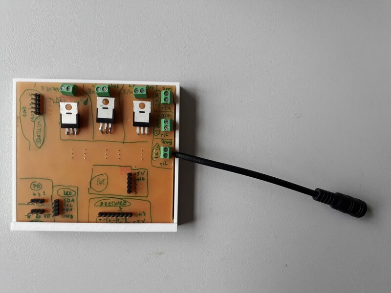
Update week 18: making my own board for the final project.
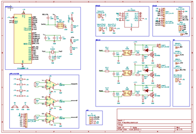
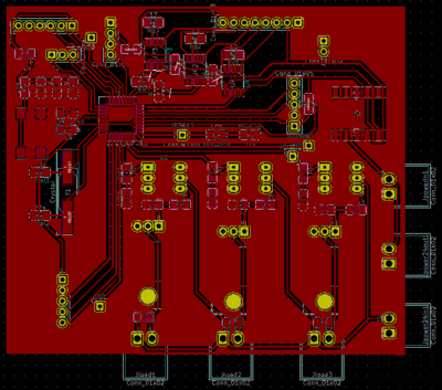
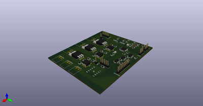
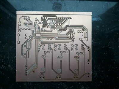
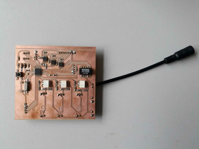
After some prototyping steps using my satshakit, I made my own board, including among other the outputs and inputs chains. Since I did not redesigned the satshakit, and this is mandatory for this week’s assignment, the integrated board will also count for this week assignment, since it communicates using I²C with an LCD, as I tested with the original I²C. This board is made of:
- The satshakit base (i.e. an ATMega328P with a 16Mhz crystal)
- The inputs (acquisition chain for pressure sensor, connections to the switches and potentiometers)
- The outputs (PWM driver, connections to the LCD)
- A power management system described below
- Interface and prgramming connections: (SPI and FTDI)
(you can click on the schematics and pcb layout images to show the pdf)
This is fully described in the final project’s page
Step 4: group assignment
Work in progress..