Moulding and casting
Objectives of the week
- Group assignment
- Review the safety data sheets for each of your moulding and casting materials, then make and compare test casts with each of them
- Individual assignment
- Design a 3D mould around the stock and tooling that you'll be using, mill it, and use it to cast parts
I do a lot of moulding for my research, but I use quite complex processes, using 3D printed moulds and centrifugation. For this week, I would like to test simple moulding processes and make some soft robots.
What I did
- Soft tube robots demonstrators
- Compared different types of silicones and moulds
- Used the vinylcutter
What I learned
- That milled mould can give excellent results... bot not for my demonstrators
- That vinylcutter is an underestimated tool
If I had the time to go further...
- I would have made more demonstrator, with no leakage!
- I would improve my documentation to share more easily the demonstrators
Files and resources
Step 1: group assignment
Long documentation for the group assignment this week, which can be found here, on the group site.
Step 2: planning my moulding
For my research in soft robotics, I make a lot of moulding, but using quite complex processes (centrifugation, multi-part mould, inserts, …). My objective for this week was then to make a frugal and simple tubular soft robot demonstrator, using the fab lab’s tools. Benjamin Gorissen made a very simple and beautiful soft actuator at small scale, that I found very inspiring. The Soft Robotics toolkit is another great initiative, gathering a lot of resources and project on a single platform.
After a little bit of brainstorming, I decided myself for this week. My goal is to make the simplest tubular soft robot demonstrator using the fab lab’s equipment. The principle I want to demonstrate has been studied a lot by Connolly.

The principle is the following. Using a perfectly symmetric silicone body having an internal channel filled with pressurized air, and an asymmetric reinforcement (with thread in Connolly’s paper), it is possible to guide the deformation of the silicone body when the pressure is increased. I will mould the silicone body, which is simply a tube, and I will use the vinyl cutter for the reinforcement.
Step 3: making the mould
Designing the moulds
For this, part, I take inspiration from Benjamin Gorissen’s method, making it even simpler. We don’t need a perfect precision, and we are working at larger scale. I want a simple tube closed at one extremity. To compare, I will design 2 mould: one to be milled (the dimensions are limited by the diameter and length of the mill), and one to be 3D printed (the quality is expected to be lower). I make arrays of the moulds, that are just negative of the tube, and are open at the top. Here it the mould to be milled:


And here is the mould to be printed (I add a little wedge at the top to avoid the silicone to flow apart):


| Length (mm) | Outer diameter (mm) | Inner diameter (mm) | Wall thickness (mm) | |
|---|---|---|---|---|
| Milled mould | 35 | 16 | 10 | 3 |
| Printed mould | 55 | 16 | 8 | 4 |
Milling the mould
To mill the mould, I used a similar process than developed in week 8. Using HSM works, I planning the milling in 2 parts: first a pocket to remove all the material at the top of each sample (so the silicone will close the tube), and then a contour for the deep tube itself. The thickness of the walls of the tube has been calibrated to be exactly the same as the mill diameter, otherwise I should have made a pocket or multiple contours.
I use wax for the mould material, because of its availability in the lab, and because it will give me a good finish. I used a 3 mm mill, that I had to change and calibrate first. Since the mill was especially long, we could not use the automatic height calibration that require to add a button between the stock and the mill. Christophe (that helped me during the whole milling process) showed me how to use a sheet of paper for the calibration: place a sheet below the mill, and lower the mill until you cannot move the paper sheet. Note the height, remove the sheet, and go 0.1 mm lower than with the sheet! Since the stock is the same size than my mould, I have to place it carefully! Christophe learned my another trick, which is to cut manually a very thin cut in the martyr, along the x axis of the machine. You can then simply fix the piece (here using double sided adhesive) along this line!


The milling of the was very easy for the machine, and give a good result! However, the inserts seem a little bit weak, and as I went deeper that the cutting length of the mill, I have some residues left be to contact of the body of the mill against the wax at the top of the mould (that can be still removed).
Printing the mould
As a backup solution, for the comparison, and to make longer moulds, I ilso made 3D printed moulds using the Prusa of the lab (week 6).

As expected, the finish is better with the milling machine, but 3D printing this geometry is more straightforward and avoid the limitations of the CNC (height, mill diameter, stock, …).
Step 4: moulding silicone
Now that I have the moulds, let’s use silicone! I will use two silicone with extreme (~900%) deformation capabilities and softness: Ecoflex 0030 and Ecoflex 0035 fast.
Safety requirements
Available here, those product are certified skin-safe! Those are “kind” product, not considered as hazardous substance, is not labelled by any pictogram (indicating special cares or point of attention).
The first one takes 4 hours to cure, wile the second one only 30 minutes, and has only 5 minutes pot life! The 35 fast allows then to have rapid results and validation of the process, but is difficult to use properly (degassing, etc.). Here is the complete moulding process (in italic, only made with Ecoflex 0030):
- Pour the two parts of silicone with a 1:1 ratio
- Mix the components
- Degas it using a vacuum pump
- Pour the silicone slowly in the mould
- If needed, degas again once the silicone is on the mould
- Wait for the silicone to cure
- Remove the silicone from the mould by pulling on it. It is possible thanks to the extreme deformation of the silicone. Using ethanol or isopropanol can ease the demoulding by making the silicone sliding.


Materials comparison
As expected, the Ecoflex 0030 gives better results, since it can be degassed and use not in a hurry. Contrarily, we can see bubbles in the Ecoflex 0035 fast, but it allows to have very quick samples!
Mould comparison
Still as expected, the wax gives smoother results. However, for this application, the 3D printing seems a betted solution. We don’t need the sample to be perfect, the sample are not limited in size and geometry, and the sample can be easily demoulded without breaking the mould… Indeed, I broke 5 of the 8 inserts while demoulding from the wax!

Step 5: cutting the reinforcement
The principle here to use and external reinforcement with stiffness asymmetry. When inflated, the soft tube will expand more in the less rigid directions. I design 4 different reinforcement, using parametric design FreeCad. Those designs are supposed to be wrapped around the tubes. This will make all sense in the last section of this week.
As dimensions’, I use a widht of 55 mm (OD= 16 mm –> circumference =16.pi = 50 mm; plus 5 mm for the overlap) Concerning the length, I use 60 mm (longer than every sample).

I can now use the vinylcutter to cut the reinforcement (week 4). After several tries, I faced 2 main problems:
- Nothing adhere with silicone (this is why there is an overlap), and the vinyl doesn’t adhere enough with itself on the overlap part. Solution: let’s use double-sided adhesive!

- Even with double-sided adhesive, the overlap is too small for the adhesive to adhere correctly with itself. Solution: increase the length of the overlap to 10 mm!

Here is the final process for the reinforcement:
- Put one side of the double-sided adhesive on a sheet of paper
- Cut it using the vinylcutter
- Extract the part that you need and remove the protection of the second side of the adhesive
- Wrap it around the tube, and it’s done!


Note that other types of adhesive, if strong enough, could be used!
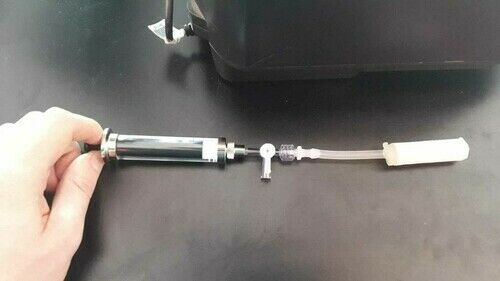
Step 6: assembling demonstrators

To test your sample, you still need to add a pressure line and a connection to a pressure source. For this you need a little bit of material:
- Ecoflex 0035 fast to be used a glu, to seal the connections
- A silicone tube of ~10 mm diameters
- A syringe pump with a luer lock output (to ensure no leakage)
- A lueur lock to tube connector, for example of this kind.
Then, simply assemble the components, using Ecoflex 0035 fast between the connection tube and the soft demonstrator.
Leakage: Leakage is a key challenge here! an even better solution would be to use real silicone glue (that has a better adherence with the connection tube) instead of Ecoflex 0035 fast.
Step 7: testing the demonstrators
As a reminder, here are the different kind of reinforcement:
Without reinforcement

Without reinforcement… Nothing funny happens!
Bending
The side of the tube where the paper is not cut cannot elongate… It bends!
Extension
The soft tube can only inflate in it axis, the paper ensure no radial expansion… It elongates!
Expansion
The cuts are this time along the length… It expands!
Twisting

cuts form an helix around the soft tube, we have twisting!
Conclusion
The demonstrators works better than expected!! Even if it was not that simple to design and test, the final process is extremely simple and straightforward using the fab lab’s equipment, and allows to demonstrate how small changes in a simple design allow to generate very different movements!