Applications and implications
Objectives of the week
- Individual assignment
- Propose and describe a final project masterpiece that integrates the range of units covered
This week will be the occasion to clarify the final project. I already described a lot the project in the project development page and in the previous weeks, but I will try to clarify it this week!
Context and description
- What will it do?
- Who's done what beforehand?
- Why would I do this?
What?
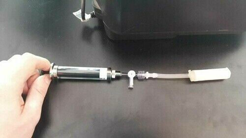
The aim of my project is to make a modular platform for the characterization of soft robots. Soft robots are made of compliant materials, and are actuated using the pressure of a fluid (here air). As an example:
And when inflated:
To come back to my final project, to aim is to provide a modular setup that can be use to characterize those kind of soft robots in term of motion, typically bending. This setup should be composed of 3 main parts:
- A pressure control system to actuate the soft robot
- A modular structure to fix the soft robot
- A tracking system to characterize the soft robot
- (And a soft robot)
Inspiration: the Soft Robotics Toolkit’s control board
The Soft Robotics toolkit is a great initiative, gathering a lot of resources and project related to soft robotics. Looking a little bit in detail in the toolkit, I found the Soft Robotics Toolkit control board, which describes a project very similar to mine!
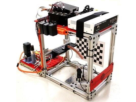
This will be a great source of inspiration for my final project. However, the control board project focus more on the pressure control part. I want to make an even more “frugal” and modular version of this characterization structure, and adapt it to my needs. As a vision for my final project, and depending to what it will lead to, a great achievement for my project would be to be integrated in the Soft Robotics Toolkit, as a complement of the control board.
Why?
Now that you have an overview of what I plan to do, let’s ask the important question: why? I have personally a lot of interest in soft robots. Those robots are typically actuated using a pressurized fluid that deforms the soft material and generate a movement. I study these soft robots for endoscopy and minimally invasive surgery. Thin, long, and actuated tube (catheters) can be used as navigation tools via the natural pathways, to reach remote locations of the body.

An example of a soft catheter I developed, and that needs to be characterized:

These catheters must be thin and able of complex movements, as tentacles. In order to assess their potential, they must be fully characterized. This the aim of this project: provide a modular platform for the characterization of soft robots. In particular, the aim here is to characterize the motion of the catheter, using typically the angles and curvature radius generated, and evaluating the workspace that can be reached by the catheter.
Other resources
I have identified several other resources that can be useful and/or related to the project.
- Soft Robotics Toolkit
- Interesting papers:
- Fab Academy final projects:
- Other stuffs
Conceptual design
Pressure control system
This is the core part of my project. Here are the main requirement for the pressure control system:
- 3 Channels with independent control
- To possibility to control air pressure with a precision of 0.05 bar at least, between 0 and 2 bar.
- An interface with a computer with a feedback on the pressure
Here is a diagram of the designed system:
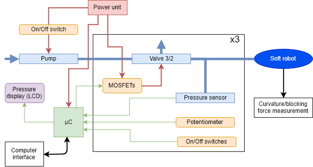
The blue parts are related to the pressure, and the yellow ones to the interface. The microcontroller would be connected to a computer to control the board using an user interface. The pressure value display is optional here (it would allow standalone operation, i.e. without connection to a computer).
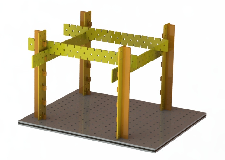
Modular structure
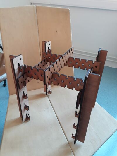
This part is more simple, and is mostly related to the use of fabrication processes learned during the fab academy. The aim here is to provide a modular and low-cost structure, that could be adapted for multiple types of measurement (video 3D tracking, force measurement, …). Usually, those kind of structure are mode using aluminium profiles, but the extruded profiles cannot be made (of course) in a fab lab. I replaced the profiles by 3 types of pieces, 2 vertical and 1 horizontal, that can be laser cut or milled. This is not a “clean” design, but this is supposed to be as modular as possible, i.e. it should be possible to fix the soft robots and sensors for the characterizations in as many ways as possible. I also re-designed the “home-made” optical board inspired by Denis, my instructor, that I developed a little bit in week 3. Here is the designed structure:
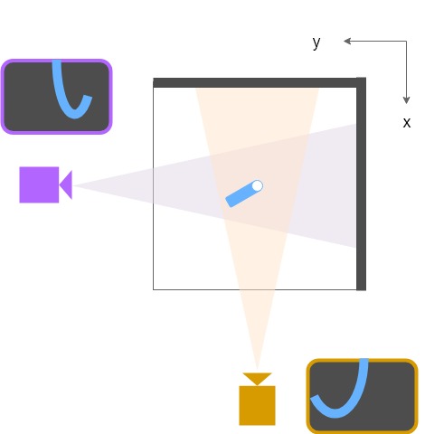
Tracking system
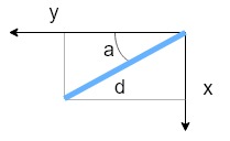
As first characterization method, I’d like to implement a 3D tracking system using only one (or two) camera. This third part is a little bit out of the scope of the fab academy, since more related to programming and image processing. Of course, this part will continue after the fab academy, since I will need it to characterize my soft robots! Here is the setup I imagine for the tracking. I want to be able to know the position in my soft robot in the 3D space, and among others recover its curvature. For this, I make the following big approximation: the soft robot can be considered as a line. Based on 2 perpendiculars images, it is possible to compute the position of each point of my soft robot line: d2=x2+y2 and a=atan(x/y).
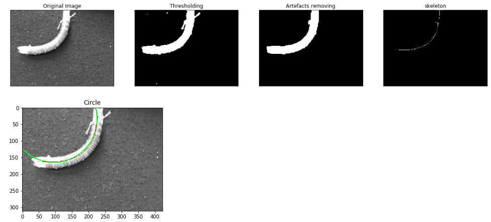
Concerning the image processing part to extract a line from the captured images, here is the planned workflow:
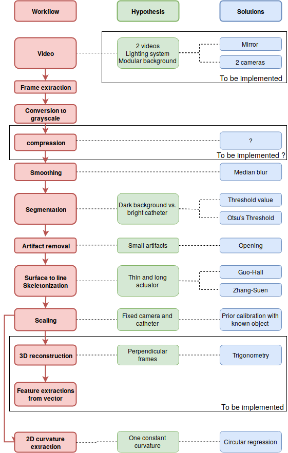
A real-time system would be advantageous, but this seems to be over ambitious, and it is not mandatory. Consequently, this third part is not very related to the two first ones, but give them a purpose!
The soft robots
This is not completely part of the project neither, but the fab academy will also help me with my soft robots.
Design, material, processes and fabrication
- What will I design?
- What materials and components will be used?
- Where will they come from?
- How much will they cost?
- What parts and systems will be made?
- What processes will be used?
Pressure control system
Design processes
- Electronics design
- CAD
- Programming
Fabrication processes
- Electronics production
- Laser cutting
Bill of materials
What has already been done
Week 11 and 12, respectively on inputs and outputs devices, are completely relevant for this part of the project, and the development of the board will be done for those weeks. As microcontroller board, I made my own Stashakit board.
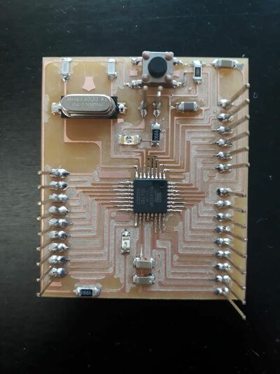
Well, at the moment I write those line, the weeks 11 and 12 are still in progress, so you can go directly check the documentation on those pages! Future weeks will also be used for this part, as the week on interfaces programming and communication.
Modular structure
Design processes
- CAD
Fabrication processes
- Laser cutting
- 3D printing
Bill of materials
What has already been done
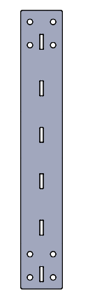
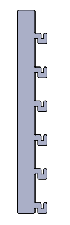
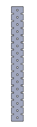
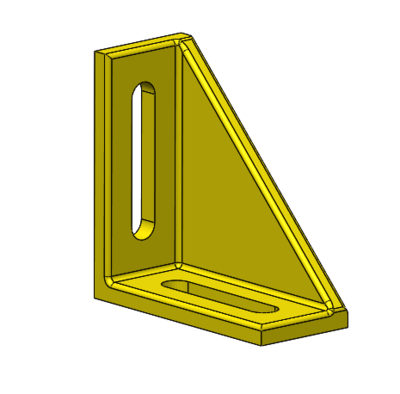
All the process has been documented in the project development page, but here is the designed structure. The 3 “simple” components:
And the structure assembled.
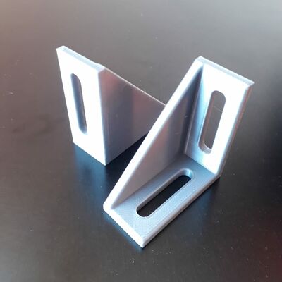
The home-made optical breadboard that I plan to use as support must still be done, or I could use optical breadboards I have in my lab. I also need fixations between the optical boards and the structure, that I 3D printed:
Tracking system
Design processes
- CAD
Fabrication processes
- 3D printing
Bill of materials
What has already been done
Concerning the hardware part, the way to fix and place the cameras, and to obtain the images must still be defined, but will most probably include 3D printing.
Concerning the software image processing part, I developed it in the project development page and in week 6. Here is an example of image that I currently can obtain :
The soft robot
Design processes
- CAD
- Simulation
Fabrication processes
- 3D printing
- CNC milling
- Moulding
- Vinyl cutting
What has already been done
As I said, the development of the soft robot I want to characterize is not part of the fab academy. However, I used the week on moulding to make some very simple demonstrators, illustrating similar working principles than my soft robots. It will also be possible to test my final project with them.
Validation and evaluation
- What questions need to be answered?
- How will it be evaluated?
My final project should answer the requirements that I described briefly on the top of this page, in the conceptual design part.
Several simple tests can be imagined to test my project:
- Connect the pressure output to another pressure sensor to validate the pressure control
- Test to actuate the demonstrators
- Test the 3D tracking system by filming a known shape
- And other test, using as many soft robots as you want!