3D Scanning and Printing
- Salem AlMarri
- Super FabLab UAE
- Last Reviewed on 26/2/2019
- Last Modified by Salem AlMarri
Introduction
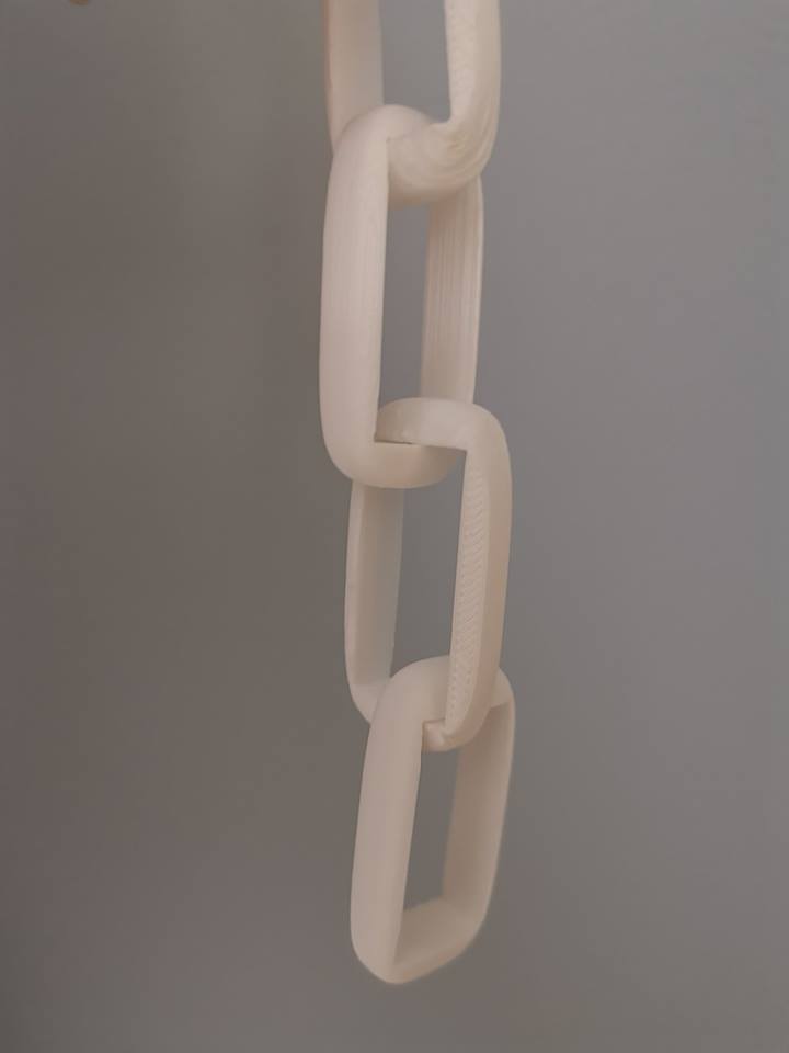
3D Printing is an additive manufacturing technique were the material is added layer by layer to form the 3D designed object. Fused Deposition Modeling (FDM) is the most common 3D Printing process were a material in a form of a spool is extruded using a stepper motor with a heated nozzle, layer by layer the 3D designed object is formed. The following designed and 3D printed object cannot be made subtractively the several rings which make up the components cannot be separated. As the additive manufacturing process begins, the rings are already printed in a way that makes it interconnected.
3D Design
In this week I learned how to use free form design from fusion360.
This basic design made inside the sculpt environment:
A sketch was drawn on one face of the design, and is then extruded to cut the body into the following object:
The same object is then replicated and rotated to form a chain:
3D Printing - Simplify3D
The additive manufacturing process of 3D printing is not possible without first slicing the CAD file in STL format into a GCODE consisting of layer by layer slices and tool paths, the file also include prespecified extruder and heated bed temperature. The slicer software used in this assignment is Simplify3D.
The default slicing option of the software has been used. Mainly, the type of material must be specified, PLA material. The infill percentage was set at 20%, which means that only 20% of design structure will be filled with PLA material. In the Layer tab, the layer height was set at 0.15 mm. A lower layer height would result in longer printing time but higher printing resolution. However, a low layer height might not be suitable in our case due to longer printing time. Although the printed component would only be 20% filled with material, the top and bottom layer are often printed solid with 3-4 solid layers.
After saving the object as STL to be imported to Simplify3D, the object is processed for printing with default settings:
It is not a good sign to have minimal contact between the object which would be printed and the printing surface:
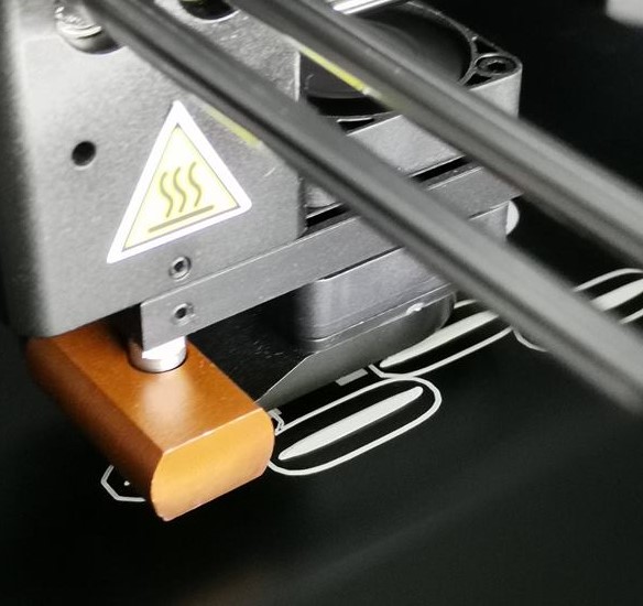
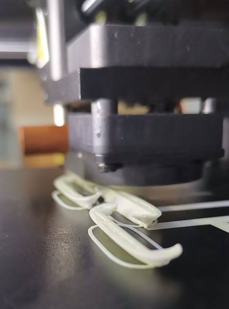
We can see signs of warping:
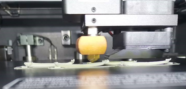
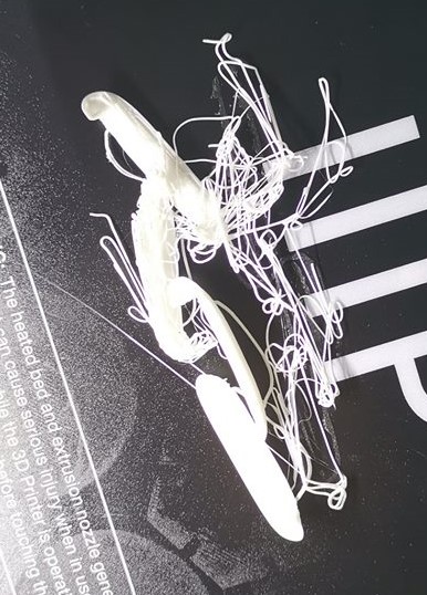
Failed print due to warping, the printed object layers from the bottom warped and there was even less contact with the build plate. In my case this caused my printed object to be displaced from its print position:
Generating support to add more contact with the build plate to prevent warping (default settings 45 degrees), not enough contact:
Generating support with 0 max overhang angle increases the number of support pillars:
Just to be on the safe side, the previous supports were added. In this step a raft is added as it is one way to prevent warping:
Raft support:
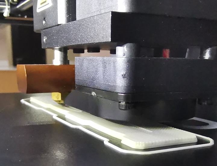
Support pillars and the object is being printed without signs of warping:
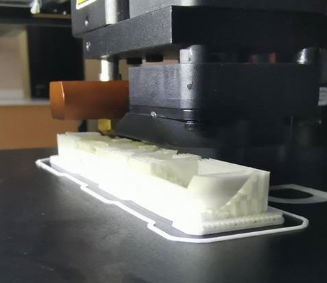
The printing process is completed, the object may now be removed and support material shall be separated:
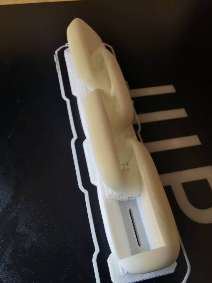
Removal of support material:
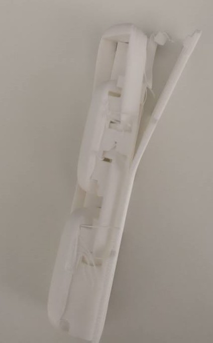
Final result:
3D Printing - Group Project
3D Scanning
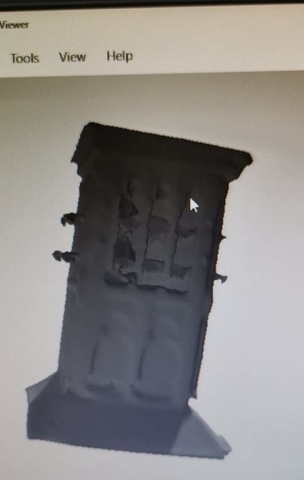
For this assignment, I am going to use the following device which is available in our fablab, Sense 3D Scanner. With a 3D scanner any real object can be scanned to become a digital 3D model. In this assignment I have scanned a Barjeel, which is a traditional wind tower used to cool down traditional houses in the Gulf region.

Loading the software, then the scanner must be pointed on the desired object which will be scanned:
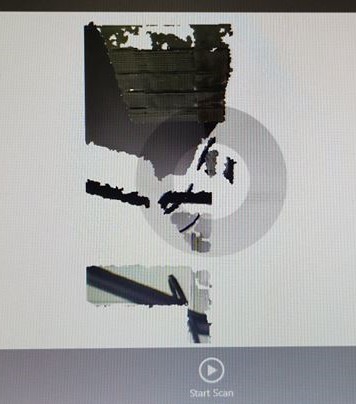
Pointing the scanner until the software recognizes the object of interest:
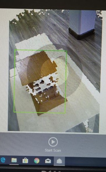
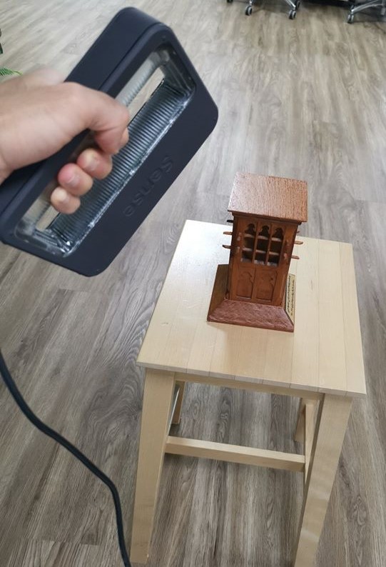
Starting the 3D scanning process, were the object is being constructed in real time into a digital 3D data / model:
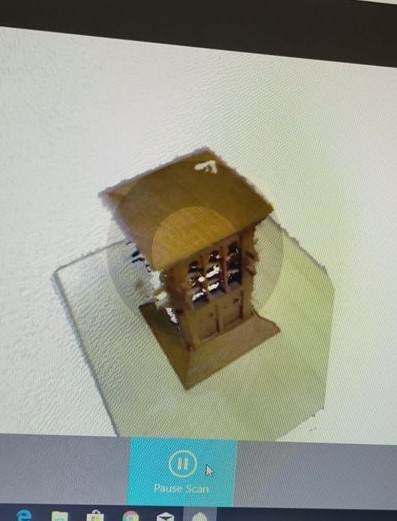
Results:
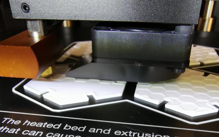
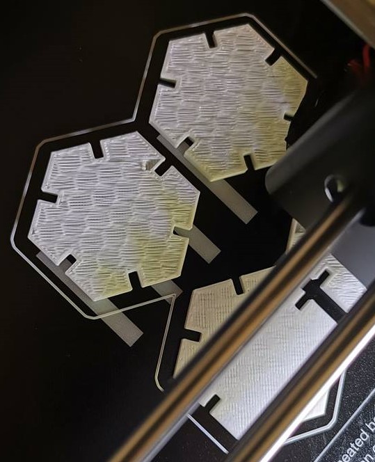
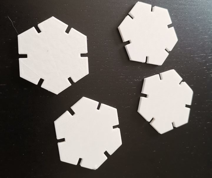
Printing Press Fit Kit from Week 4 - Extra
Assignment Files:
3DChainParametric Design Hexagon Kit