Input Devices
- Salem AlMarri
- Super FabLab UAE
- Last Reviewed on 03/4/2019
- Last Modified by Salem AlMarri
Introduction
In this week I have designed a PCB board influenced by satshakit-grbl. The board should be used for the coming week's assignment.
Schematic Design
The schematic design includes ATMEGA328P-AU, CH340G IC which would allow the use of a micro USB. In addition terminal pins would be included instead of the normal pinheads used on previous assignment. The board is designed in a way to be a potential master microcontroller for the final project, with an industrial grade feature, terminal pins. The micro USB would be used to allow easier programming, and establishment of serial communication with computers. The board makes almost full use of the ATMEGA328P-AU chip, as most of its pins are connected to terminal pins. Also additional VCC and GND pins will be added to allow input and output components to be directly powered and grounded with the board.
ATMEGA328P-AU:
As a start we need to look for the datasheet, ATMEGA328P-AU library and an ATMEGA based board design like Satshakit.
CH340G:
Is a USB to serial chip which would allow us to program our board through USB. As a start we need to look for the datasheet, CH340G library.


Board Design
In the board design we based most of the configuration of based on the Electronics Production assignment. Clearance was set to 17 mil, and routing width was 14. In addition a ground layer was added to minimize number of routes on the board based on this guide.

Fabrication
Export Pinlist of components: Previously we used to write down the components on a paper. From EAGLE we can export the pinlist which includes component name, value and orientation. Exporting the pinlist is more professional and convenient.


Time Of Flight Sensor - Input Device
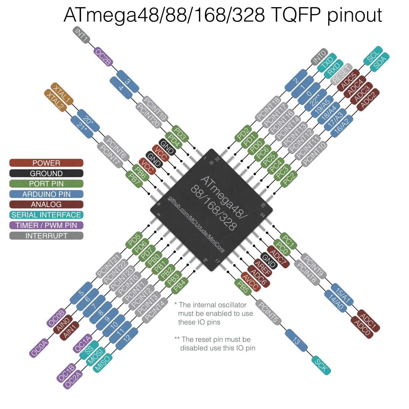
Time-of-Flight sensor, GY-53 VL53L0X (datasheet), is a high-performance proximity and ranging sensor, it faster and more advanced than an ultrasonic sensor. The sensor input was PWM, so we connected the PWM pin to a PWM compatible pin on the ATMEGA328P-AU.
To program through Arduino IDE we refer to the following schematic which include Arduino IDE pin names for ATEMGA328P-AU based boards.


Code
            byte PWM_PIN = 6;

            int pwm_value;

            void setup() {
              pinMode(PWM_PIN, INPUT);
              Serial.begin(115200);
            }

            void loop() {
              pwm_value = pulseIn(PWM_PIN, HIGH);
              pwm_value = (pwm_value)/10;
              Serial.println(pwm_value);
            }
Input Sensor - GIF
Moving the rectangular object backward and forward, the input value of distance can be seen on the serial monitor of Arduino's IDE in millimeter unit of distance.

Assignment Files:
Board (to make GND layer visible, press Ratsnest button in EAGLE)