- Salem AlMarri
- Super FabLab UAE
- Last Reviewed on 29/5/2019
- Last Modified by Salem AlMarri
Introduction
In this week, I was assigned to prepare the heart of the CNC machine. The heart of the CNC machine was GRBL, which is a free open-source software used to control motion of machines translated using any type of motors, in our case we have used a stepper motor to translate the motions from GCODE to real movement. The GRBL firmware is uploaded to an arduino controller set at the heart of many CNC machines such as laser cutters and 3D printers. The firmware requires a set of configuration to be suited for the specific type of CNC machine, requiring the configuration of several parameters such as the dimension, feed-rate, acceleration, etc. The firmware is also configured depending on the stepper motor used, type of belt, and pulley dimension.
GRBL
The GRBL version for our Kandoora Cutting Machine was GRBL 0.9i, which adds the support of a servo motor to be used as an actuator rather than a spindle. After downloading the file from github, the library must be added to Arduino, and then the config.h file of the GRBL library must be edited depending on operation nature of the CNC machine.
Homing Configuration: since that our CNC machine operates on 2 moving axis, and the actuation part is fixed, the homing configuration must specify x and y axis.
#define HOMING_CYCLE_0 (1 << X_AXIS)
#define HOMING_CYCLE_1 (1 << Y_AXIS)
Enable CoreXY Kinematics: The stepper motor and belt set up was positioned in a CoreXY format. This requires enabling the CoreXY kinematics for the CNC machine from the config.h file of the GRBL library.
#define COREXY
Configuring GRBL on Arduino Serial Port
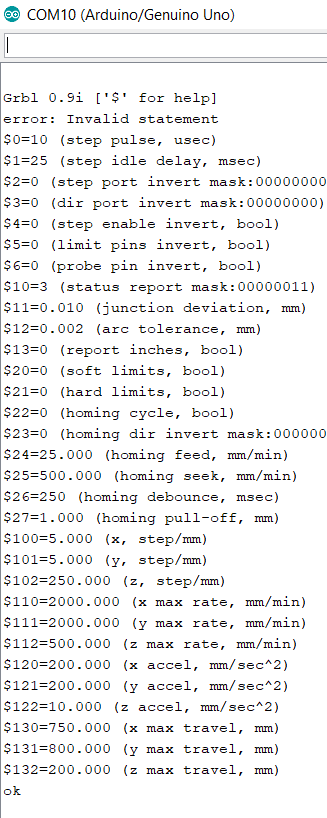
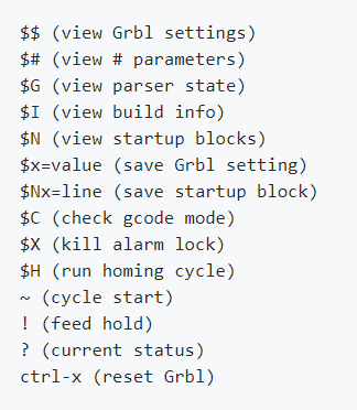
There are two configurations that take place for the CNC machine, one on the config.h file, and the other one takes place on Arduino's serial port after uploading the code to the Arduino board with instructions obtained from Configuration GRBL v0.9. After uploading the code obtained from the link to the controller, establishing a serial communication between Arduino's IDE and the controller, and writing '$' to the controller through the serial monitor, the following results are then written on the serial monitor as shown in the screenshots below.
Various parameters shown in the screenshot above must be edited such as step/mm, max travel distance, etc.
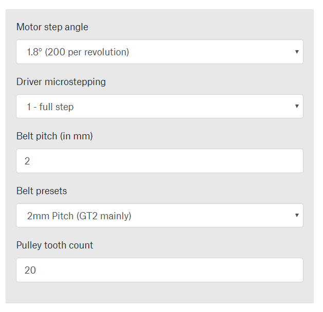
Step Per Millimeter Calculation
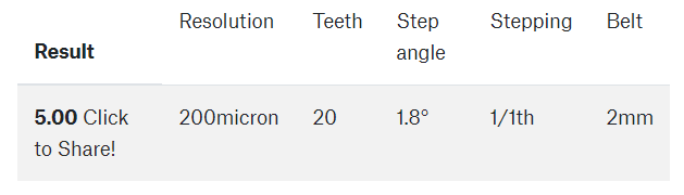
With a stepper motor driven system, it is important to calculate step per millimeter. In this website, a steps per millimeter calculator can be found. A full rotation means 360 degrees, with a typical motor a single step results in a 1.8 degree rotation, thus there are 200 steps per revolution. Driver microstepping has been set to 1, a full step. Note, a lower microstepping value means that motor's resolution has been increased but this also results in lower torque. Cutting in this case requires a higher torque, as a result the microstepping has been set to such value. The GT2 belt has a pitch of 2 mm, and the pulley mounted on the stepper motor has 20 teeth. With the above configuration, there are 5 steps per millimeter. Writing $101 = 5 to serial monitor configures the steps per millimeter.
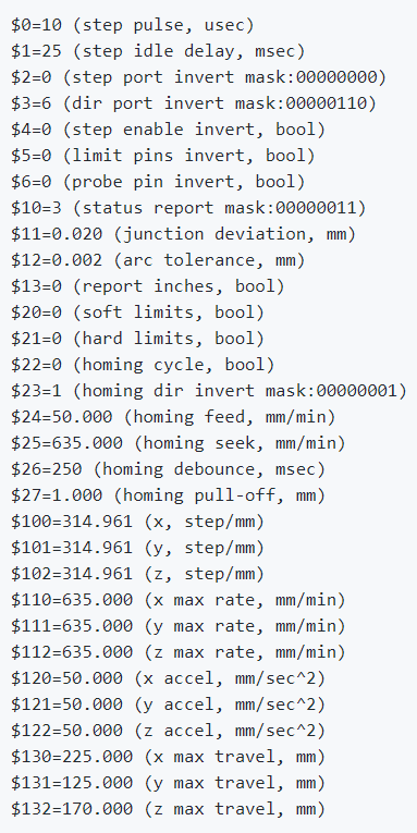
In the screenshot below, it can be seen that steps/mm parameter, acceleration parameter, and max travel parameter has been edited to suit the design of the CNC machine. From default value of 314.961 step/mm for each axis, the steps/mm for x and y parameter has been edited to 5 step/mm. The acceleration has been increased from 50 to 200. The max travel distance has been configured to 750mm in x-axis, 800mm in y-axis, and 200mm in z-axis.