Embedded Networking and Communications
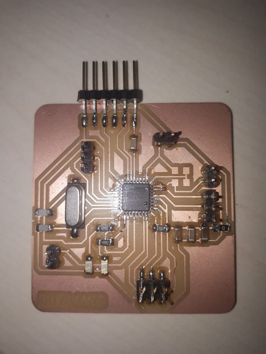
In this week we are assigned to design, build, and connect wired or wireless node(s) with network or bus addresses as an individual assignment. In this assignment I used I2C wired communication protocol
Communication Between two microcontrollers
I2C (Inter Integrated Circuit)
I2C (Inter Integrated Circuit) is serial bus interface connection protocol. It uses only two wires for communication, that two wires called as SDA (serial data) and SCL (serial clock). It is half duplex serial communication protocol and works with multi masters and multi slaves for short distance intra-board communication. Masters are the nodes that generate clock signal and initiate communication. Slaves are the nodes that recieve the clock and respond when addressed by masters.
Task Requirments
Task Procedure
Since it is not possible to use SDA and SCL pins of my board, I used to download TinyWire library which provides I2C support for ATtiny micro controllers and have only a Universal Serial Interface and copythe file and paste it in arduino libraries file. We are going to switch On/Off of the slave micro controllerLED by the command from the master microcontroller
Atmega 328/P (Master)

Since we are using Atmega 328P, the hardware support 7 bit address which equal 128 address and that means you can use 128 device from 0 to 127 on the I2C bus. Standard clock speed are 100 Khz and 10 Khz but the standard let you use clock speed from 0 to 100 Khz and the fast mode is 400 Khz and even higher speed 3.4 Mhz. After reading ATmega 328 P data sheet about 2 wire serial interface I found the following features :
The code
As we said previously that the Masters are the nodes that generate clock signal and initiate communication. We chose the SCL pin = A2 while the SCL port = Port C and SDA pin = 13 and SDA port = Port B.
ATtiny 44 (Slave)
Since We are going to use ATtiny 44 as a slave let's have a look on the USI ( Universal Serial Interface ) features:
