Week 6: 3D scanning & printing
Time is running so fast, this is already fifth week of the course. Finally, the same time, which is running so fast pushed us to work with 3D printers and scanner. There are plenty of 3D printers in FabLab Oulu. I discovered one interesting project led, planned and constructed by Mikko, who is building a machine from the scratch. It is quite impressive and wide topic as we could focus on every single part that Mikko is using/building. Nevertheless, it is time to move to the group assignments and personal work, which we did this week. Below as a teaser I'm presenting the most precise, Formlabs Form 2, which is used for high precision models. It is using laser to harden liquid material. Definitely I will work with it in the future.

Group assignment
Team once again: Gleb, Marjo, Perttu and me
Our main goal is to learn and understand the limitations of the 3D printing. Similarly to learning kerf. However, this time we are working in 3 dimensional space or three orthogonal planes. We have used test file given by our teaching assistant as we are not planning on inventing circle again. It is presented below:
We have to use three independent printers for our tests. Let me quickly introduce every single of one, which we used (I will use the specifications given by teaching assistant, as those are extremely handy in this matter):
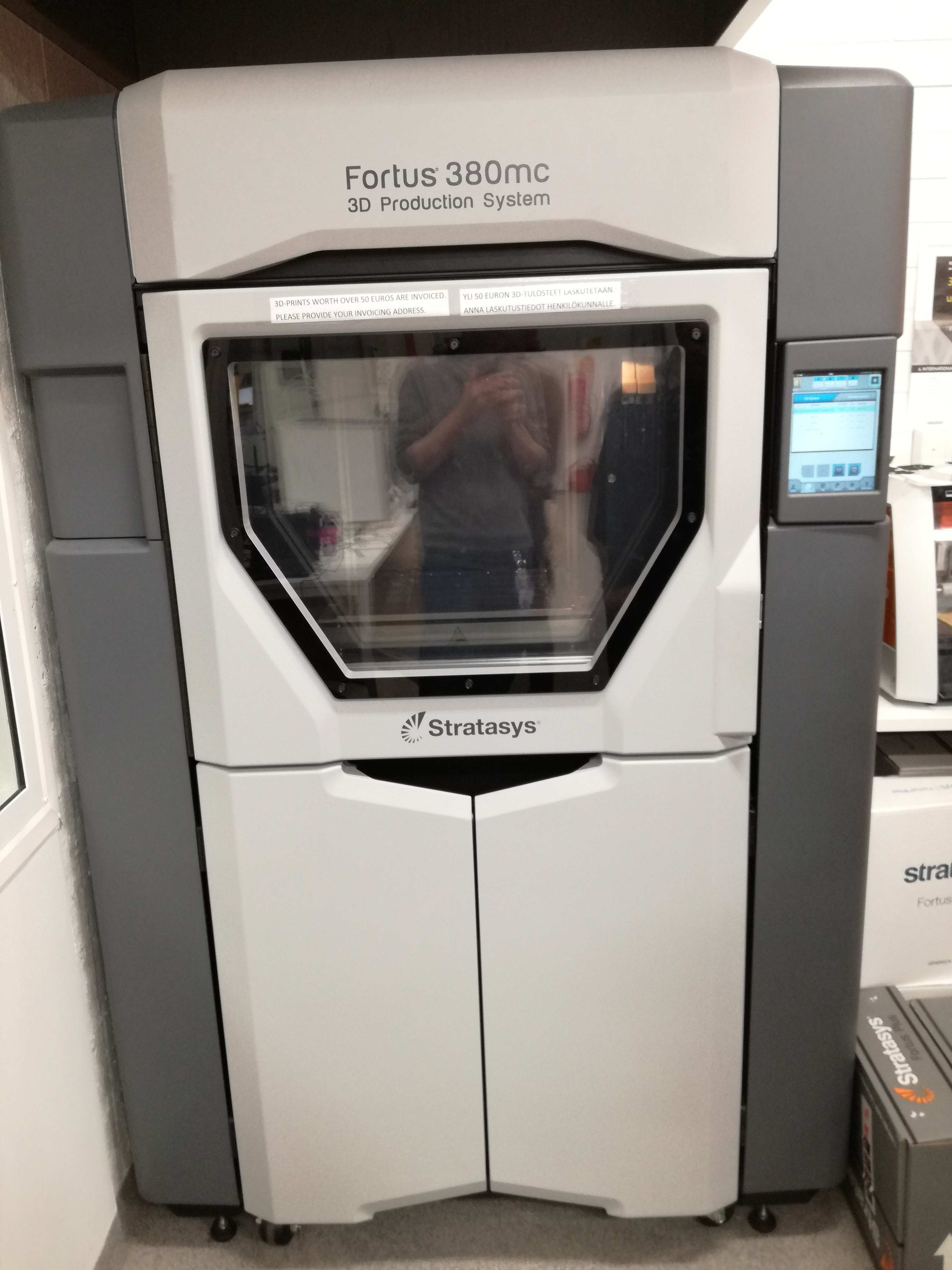
- Stratasys Fortus 380MC - the most expensive and biggest printer in our Lab
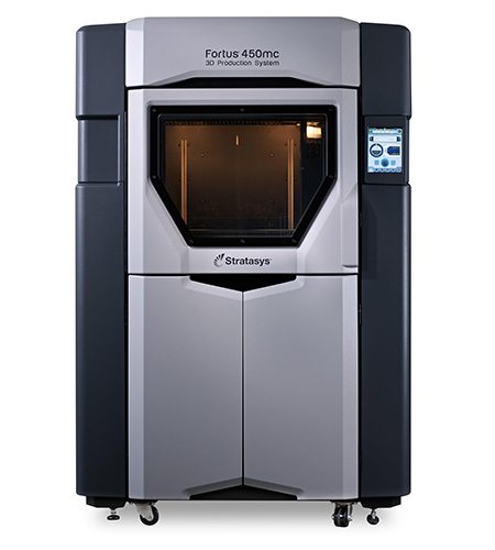
Technology: Fused Deposition Modeling (FDM), additive manufacturing process printing from bottom to top, layer-by-layer (each layer with each corresponding model material and support material)
Most common defect in FDM is warping: it happens when the extruded material cools during solidification, its dimensions decrease. Design considerations for preventing warping:
Solution: Avoiding large flat areas, thin protruding features and sharp corners
Specifications:
- Max build size: 355x305x305 mm
- Typical layer height in FDM: varies between 50 and 400 microns
- Material: ABS (Acrylonitrile butadiene styrene)
- Good strength
- Temperature resistance
- More susceptible to warping
- Software: Insight
- Support material: Yes,
Support materials are available in breakaway and soluble forms. They make it possible to create detailed geometries with overhangs and small, intricate openings. Breakaway support structures are manually removed and do not require the use of cleaning tanks. Soluble support dissolves in a detergent bath for hands-free productivity.
- Material: ABS (Acrylonitrile butadiene styrene)
- Put the gloves on while bring the object out of the 3D printer and while using spatula for removing the object from the sheet as well as for putting or removing the object from the tank containing sodium hydroxide, NaOH.
- Better to remove your glasses when you are adjusting the sheet on the surface of the 3D printer.
- At least 8 hours soaking in the tank.
- Leapfrog Creatr HS - well-known company, smallest size (comparing our choices)
Technology: Fused Deposition Modeling (FDM), additive manufacturing process printing from bottom to top, layer-by-layer (each layer with each corresponding model material and support material)
Most common defect in FDM is warping: it happens when the extruded material cools during solidification, its dimensions decrease. Design considerations for preventing warping:
Solution: Avoiding large flat areas, thin protruding features and sharp corners
Specifications:
- Max build size: 280x270x180 mm
- Typical layer height in FDM: varies between 20 and 350 microns
- Material: PLA (material) and PVA (support material)
- Software: Slic3R (require .g code files)
- Support material: Yes,
Support materials are available in breakaway and soluble forms. They make it possible to create detailed geometries with overhangs and small, intricate openings. Breakaway support structures are manually removed and do not require the use of cleaning tanks. Soluble support dissolves in a detergent bath for hands-free productivity.
- Material: PLA (Polylactic Acid)
- Same procedure as previously
- Raise3D Pro2 - elegance with good price and size

Technology: Fused Deposition Modeling (FDM), additive manufacturing process printing from bottom to top, layer-by-layer (each layer with each corresponding model material and support material) or Fused Filament Fabrication (FFF), printing process that uses a continuous filament of a thermoplastic material. Filament is fed from a large coil through a moving, heated printer extruder head, and is deposited on the growing work. The print head is moved under computer control to define the printed shape.
Most common defect in FDM is warping: it happens when the extruded material cools during solidification, its dimensions decrease. Design considerations for preventing warping:
Solution: Avoiding large flat areas, thin protruding features and sharp corners
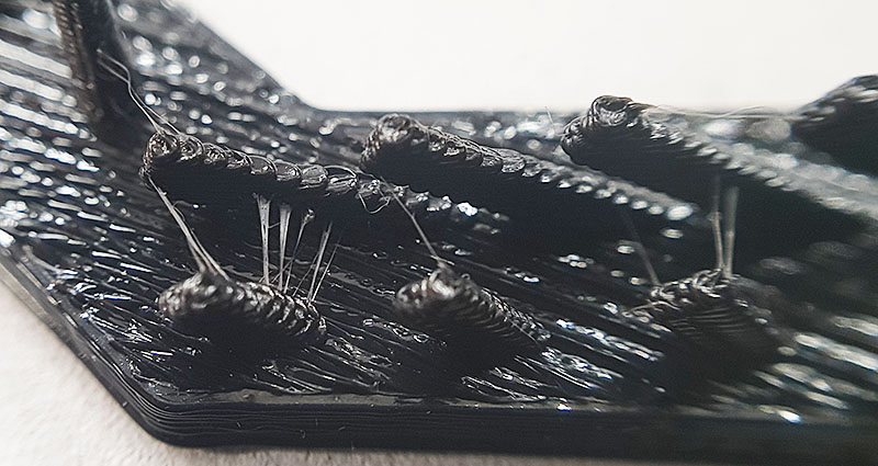
Most common defect in FFF is weakness of filaments: it happens when designed object has too thin walls/lines or nozzle is small Design considerations for preventing warping:
Solution: Avoiding thin outlines, walls and lines, use reasonable nozzle size and printing speed.
Specifications:
- Max build size: 305x305x300 mm
- Typical layer height in FDM: varies between 10 and 250 microns
- Material: PLA / ABS / HIPS / PC / TPU / TPE / PETG / ASA / PP / Glass Fiber Enforced / Carbon Fiber Enforced / Metal Particles Filled / Wood Filled.
- Software: Built-in
- Support material: Yes,
Support materials are available in breakaway and soluble forms. They make it possible to create detailed geometries with overhangs and small, intricate openings. Breakaway support structures are manually removed and do not require the use of cleaning tanks. Soluble support dissolves in a detergent bath for hands-free productivity.
- Material: ABS (Acrylonitrile butadiene styrene)
- Procedure similar to previous printers
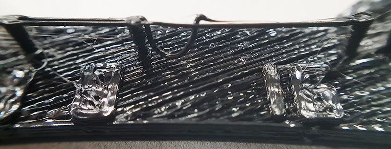
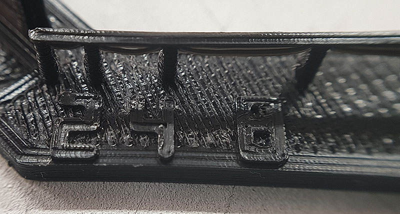
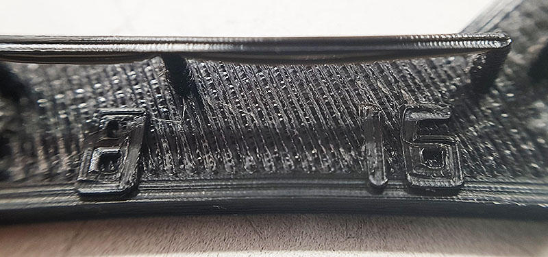
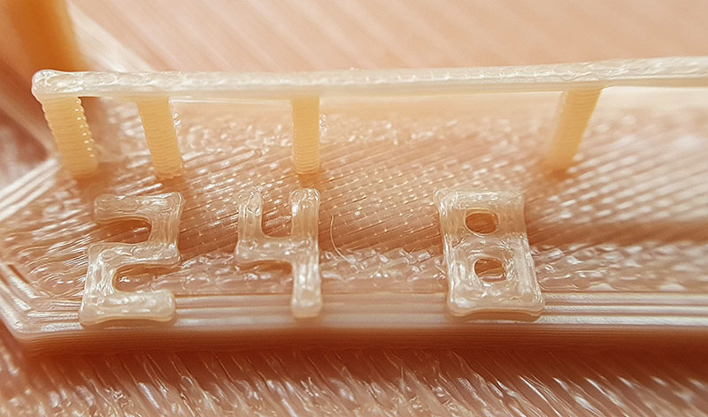
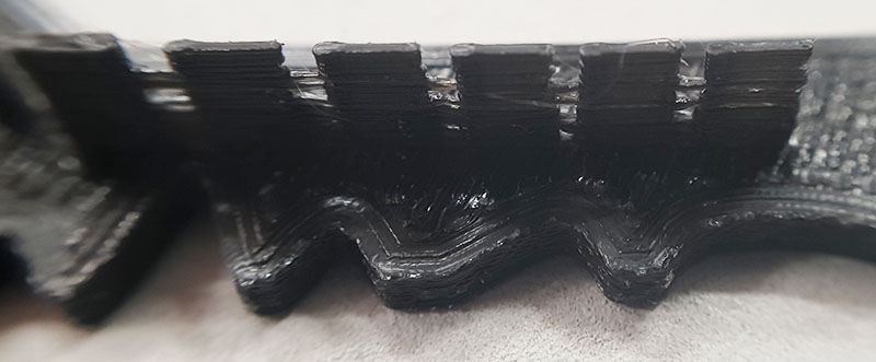
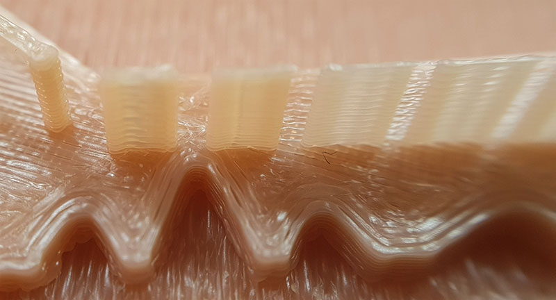
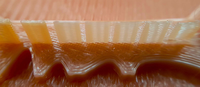
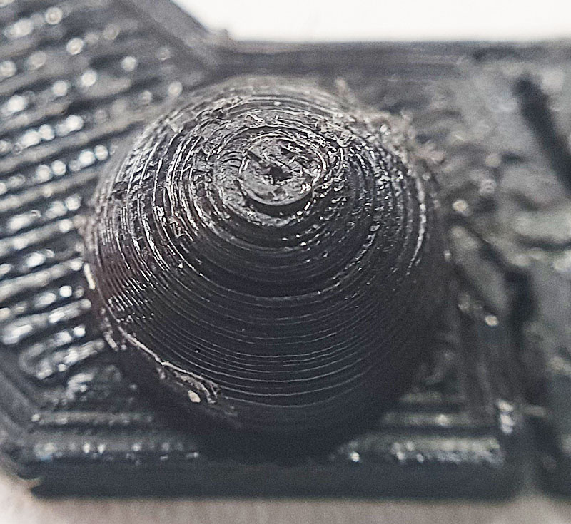
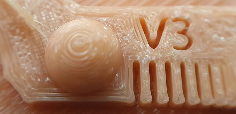
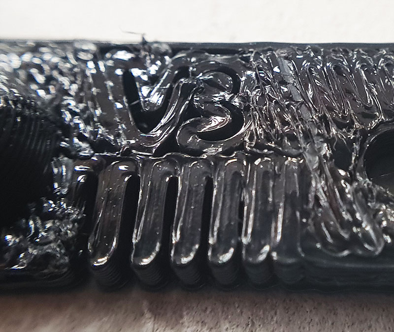
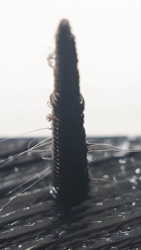
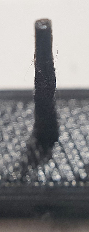
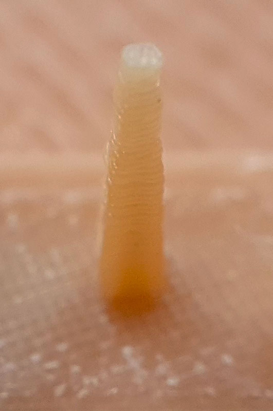
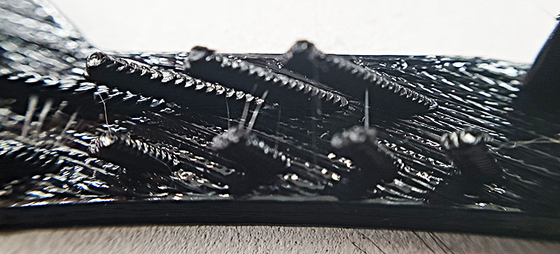
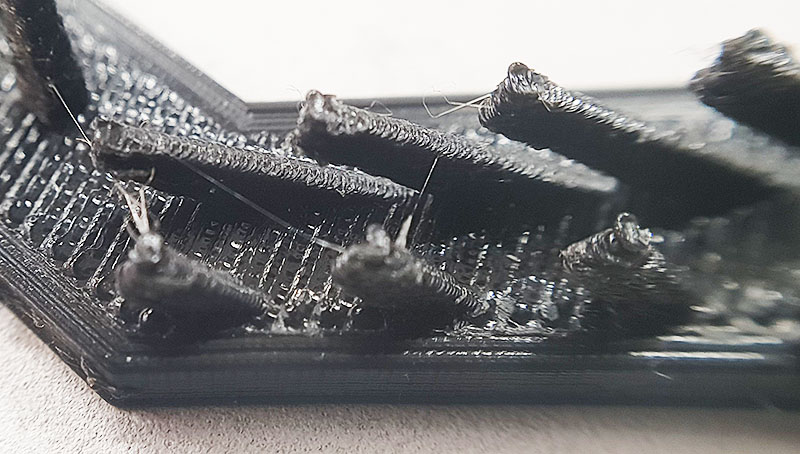
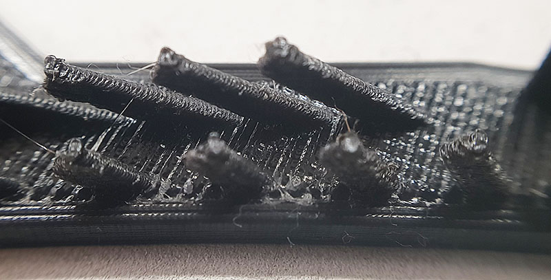
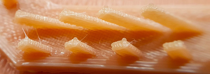
Testing the design rules
On our test sample we can define output of printing out several features such as:
  |
  |
  |
  |
  |
  |
 |
 |
 |
  |
  |
 |
 |
 |
 |
  |
  |
  |
 |
 |
 |
  |
  |
 |
Individual Assignment
3D printing
I really, really don't like to waste material, especially that printing is made with plastic. Because of that I decided that my assignment must be useful in some way. It was easier to stay than fabricate it, in addition we are supposed to show some skills in additive manufacturing.
Additive manufacturing is a process that adds successive layers of material to create an object, often referred to as 3D printing. Subtractive manufacturing, as the name suggests, is the opposite. Rather than adding layers, subtractive manufacturing involves removing sections of a material by machining or cutting it away. It can be carried out manually or, more commonly, by a process known as Computer Numerical Control (CNC) machining.
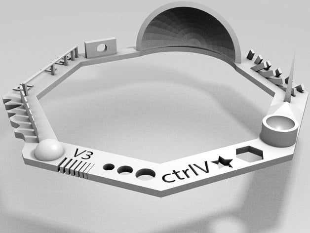
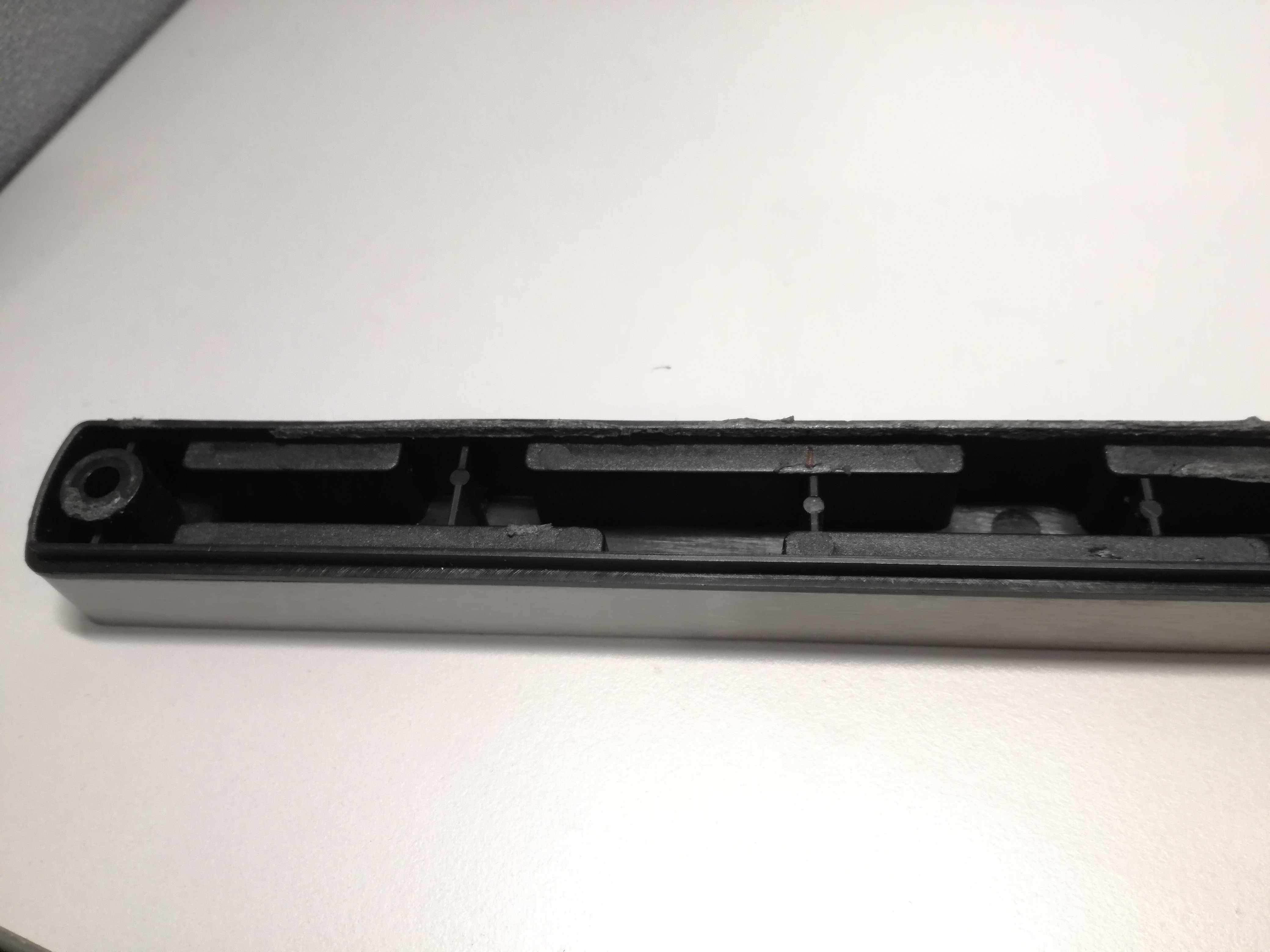
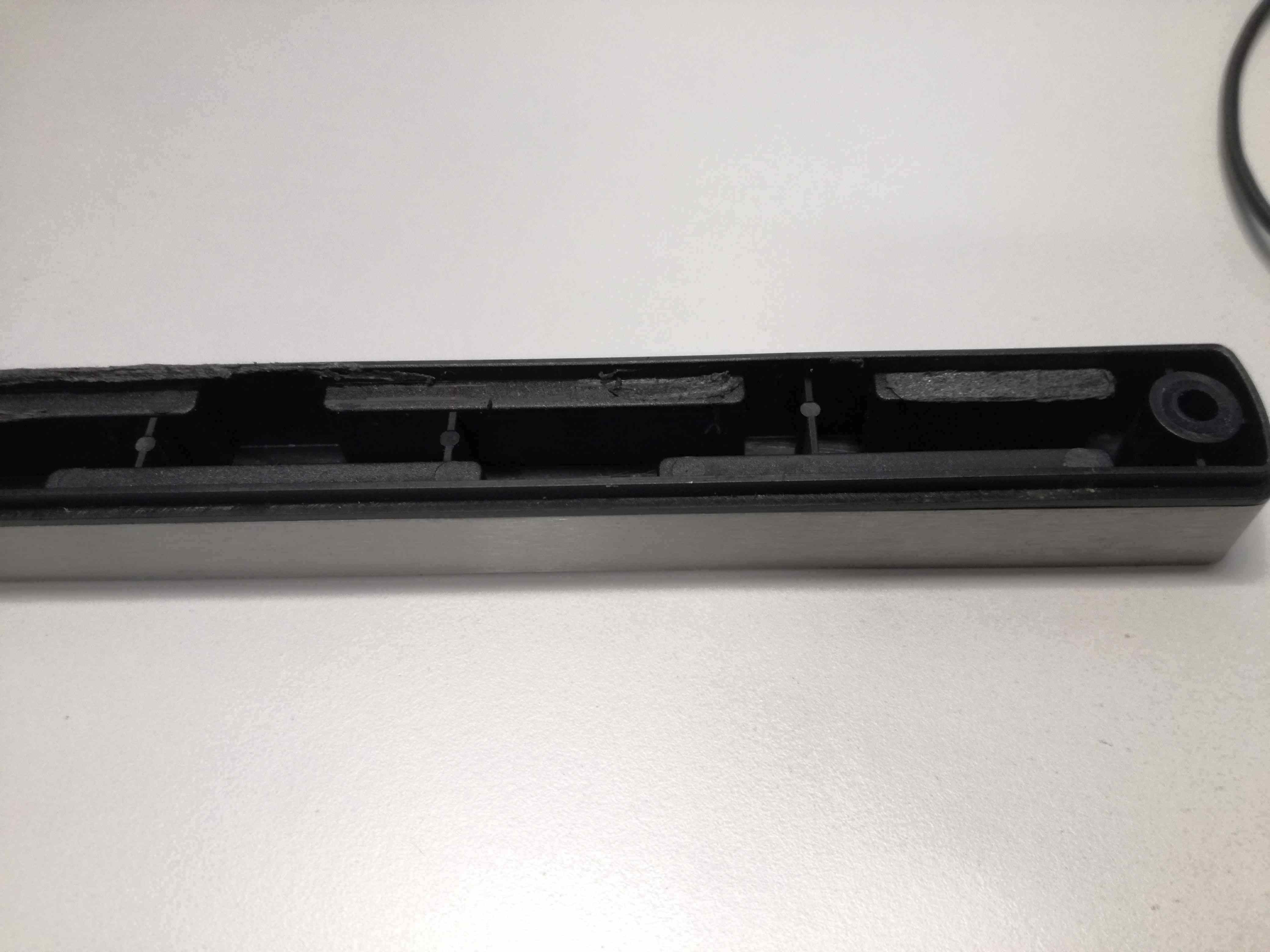
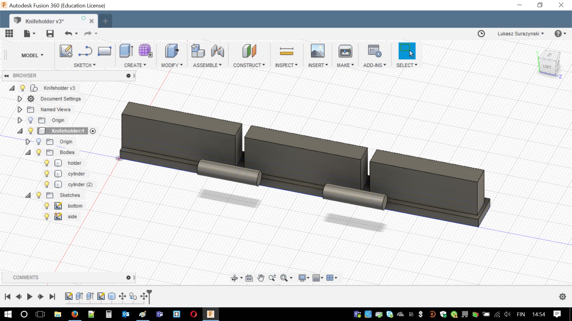
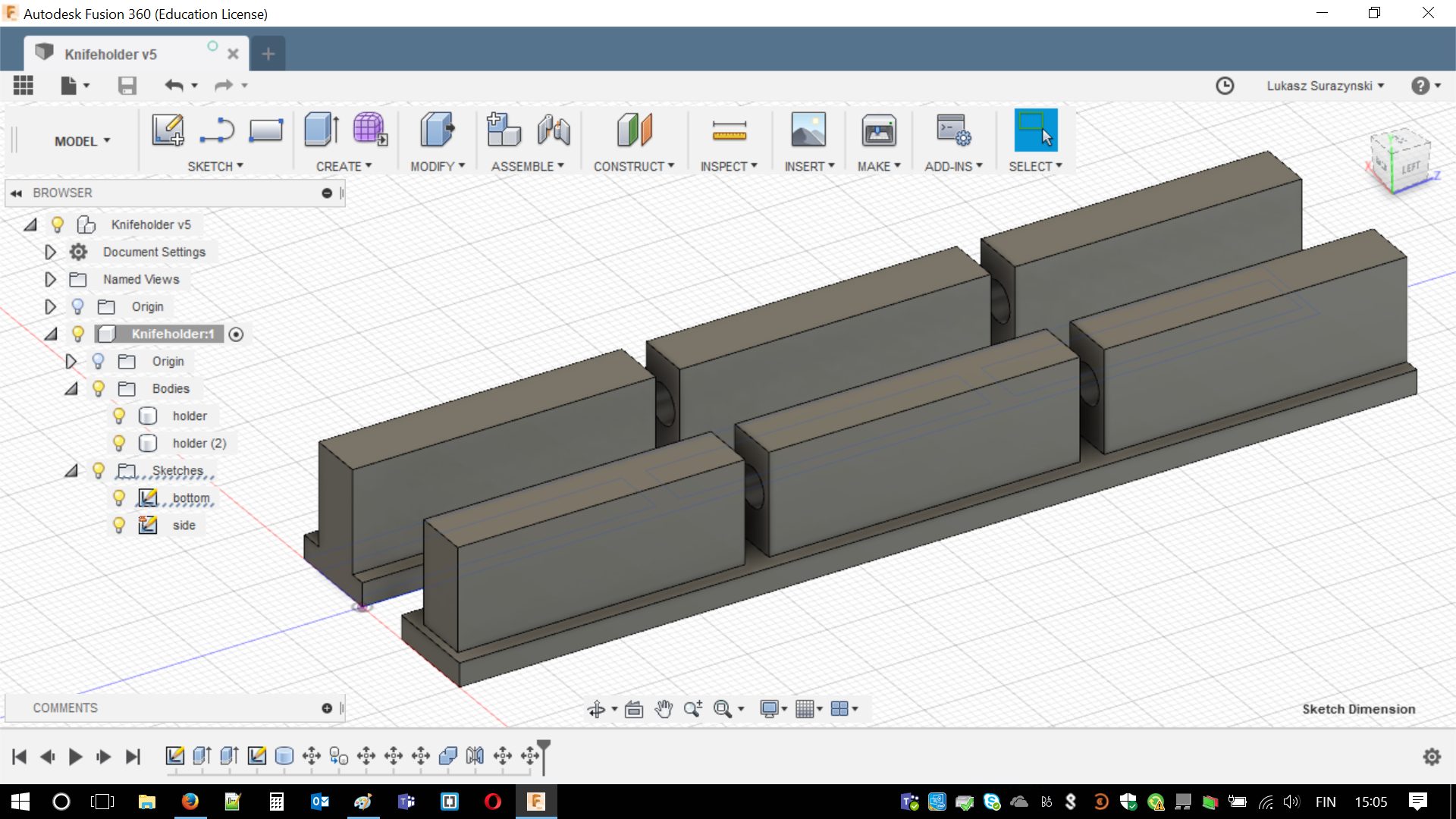
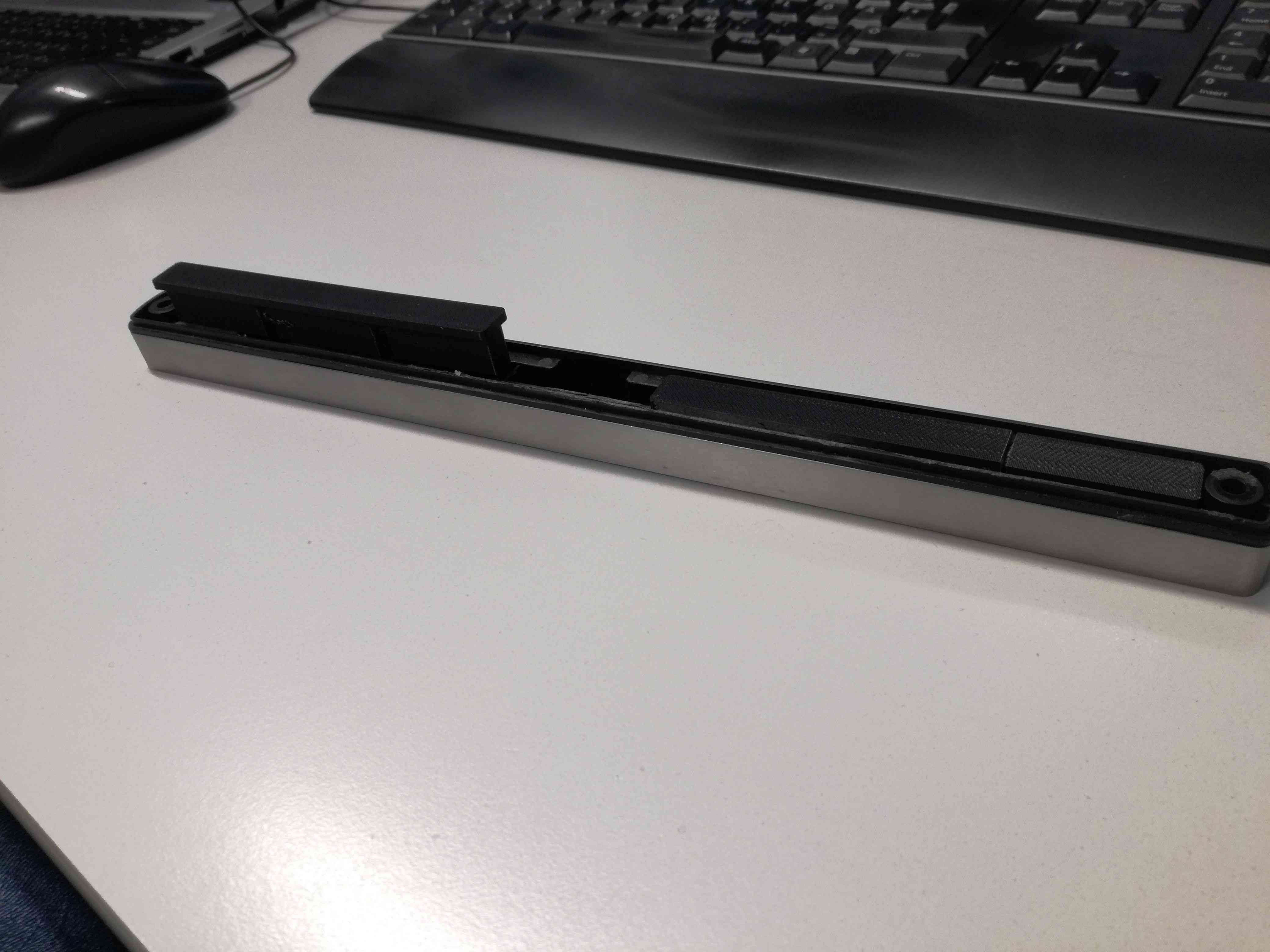
Alright! Theory is simple let's go to practice. I decided that I will design a part, which was needed for our "magnetic" / "majestic" knife holder. We didn't want to use screws with it, as it is placed on the side of a cupboard. In a result we decided to use double-sided tape. Unfortunately, there is huge gap on back-side. I had to fill it with something and then I could place it on the cupboard. I think couple photos would be helpful.
It is pretty long thing, our knife holder. I realized that it would require one long part. I wasn't sure if any of the printers is able to print something so long. I decided to print two pieces, as the knife holder is symmetrical (later I have to use mirror image on my design). I used Autodesk Fusion 360 in designing process and caliper. There are numerous tutorials on YouTube and a lot of answers on forums how to use software. List of tutorials I was using:
- Fusion for beginners
- Boolean operations in Fusion360
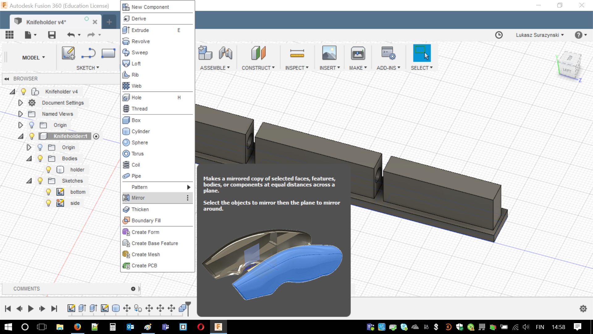
- Mirroring parts in Fusion360
- Rendering
- Animations
One of the drawbacks of Fusion360 is limited accesability. I can use it for free as long as I am a student. Most likely I would need to switch in the future. Trial version is here: Click
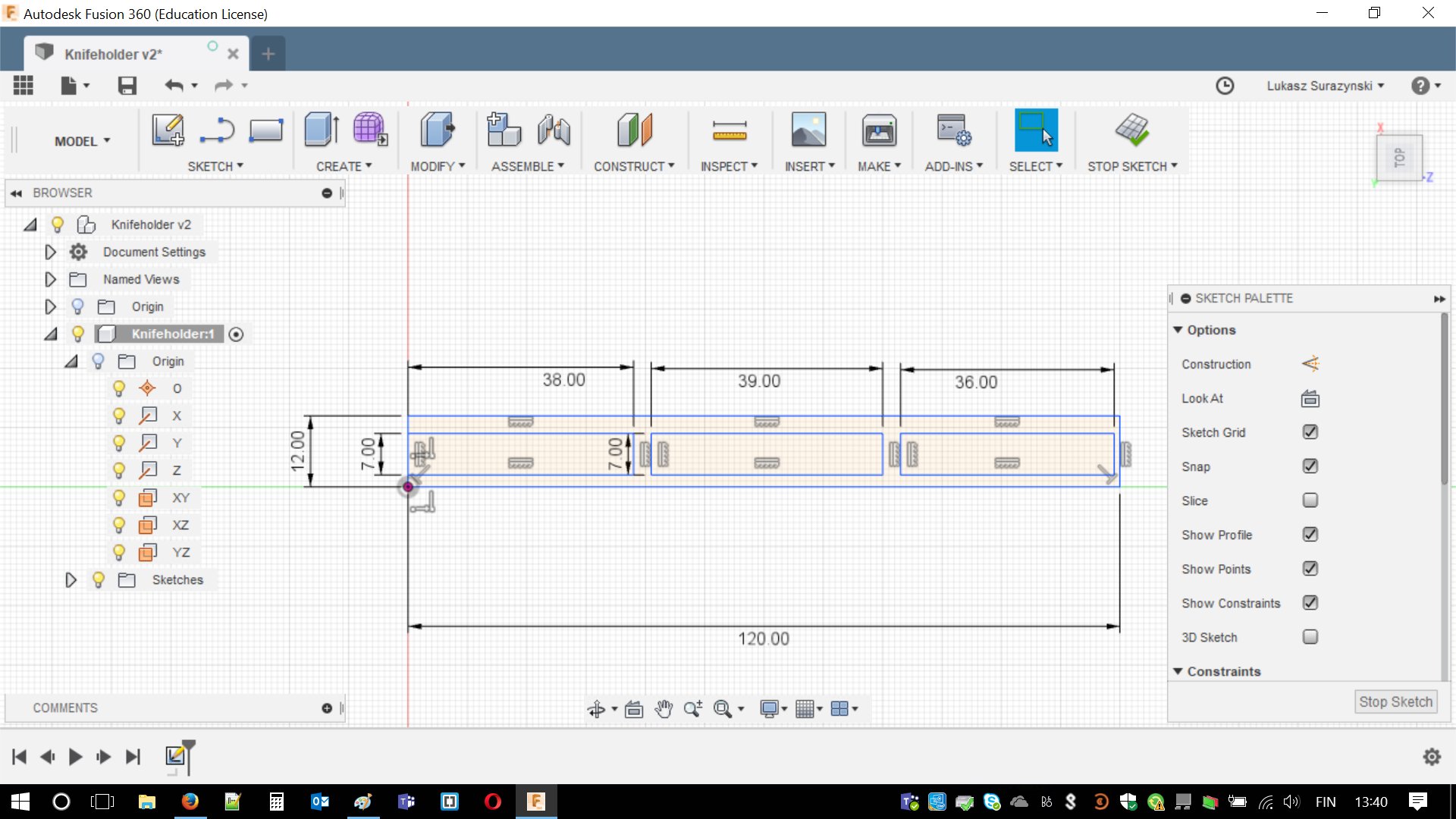
After creating sketch I realized something. Still, there is one problem. This piece can be made on CNC cutter, lathe or pretty anything. I have to complicate it a bit. For this purpose I created two cylinders and subtracted them from the remaining setup.
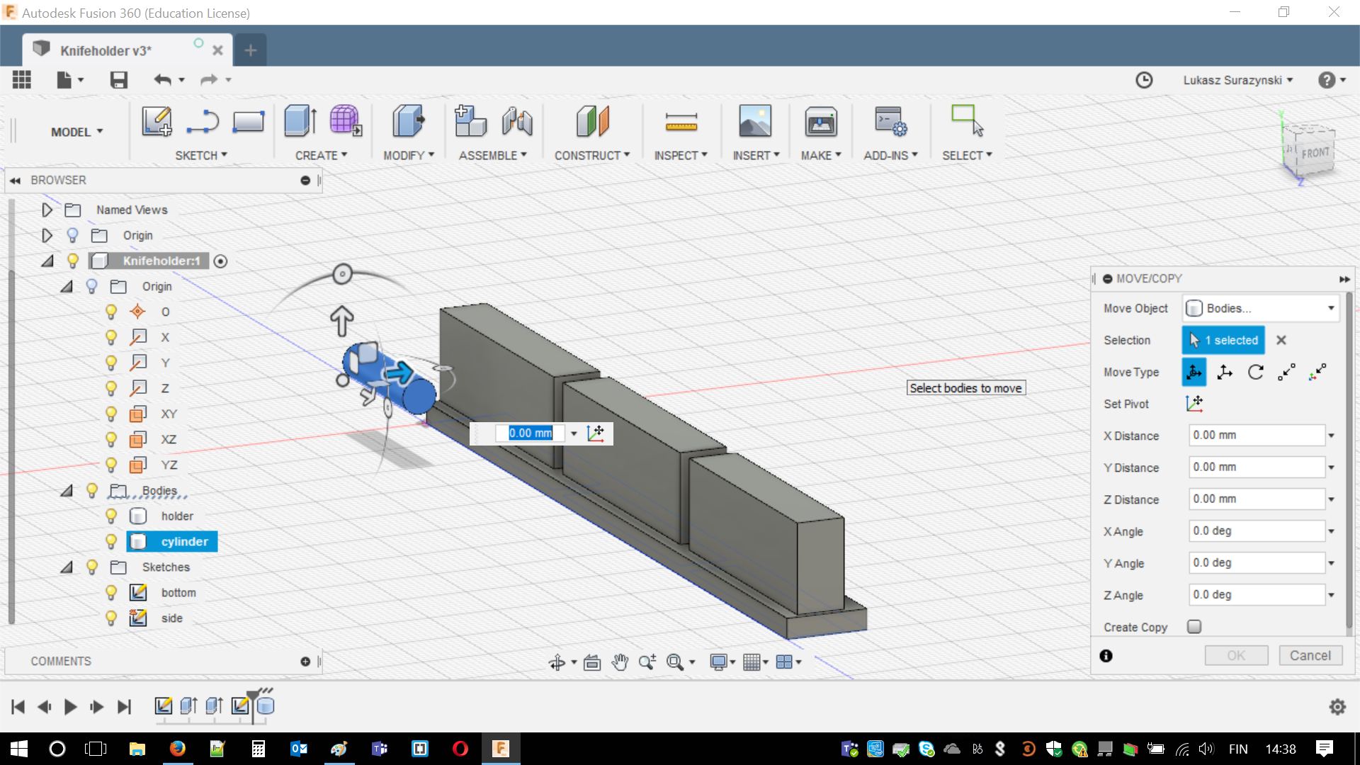
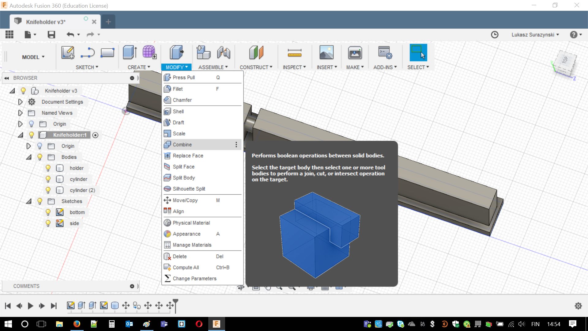
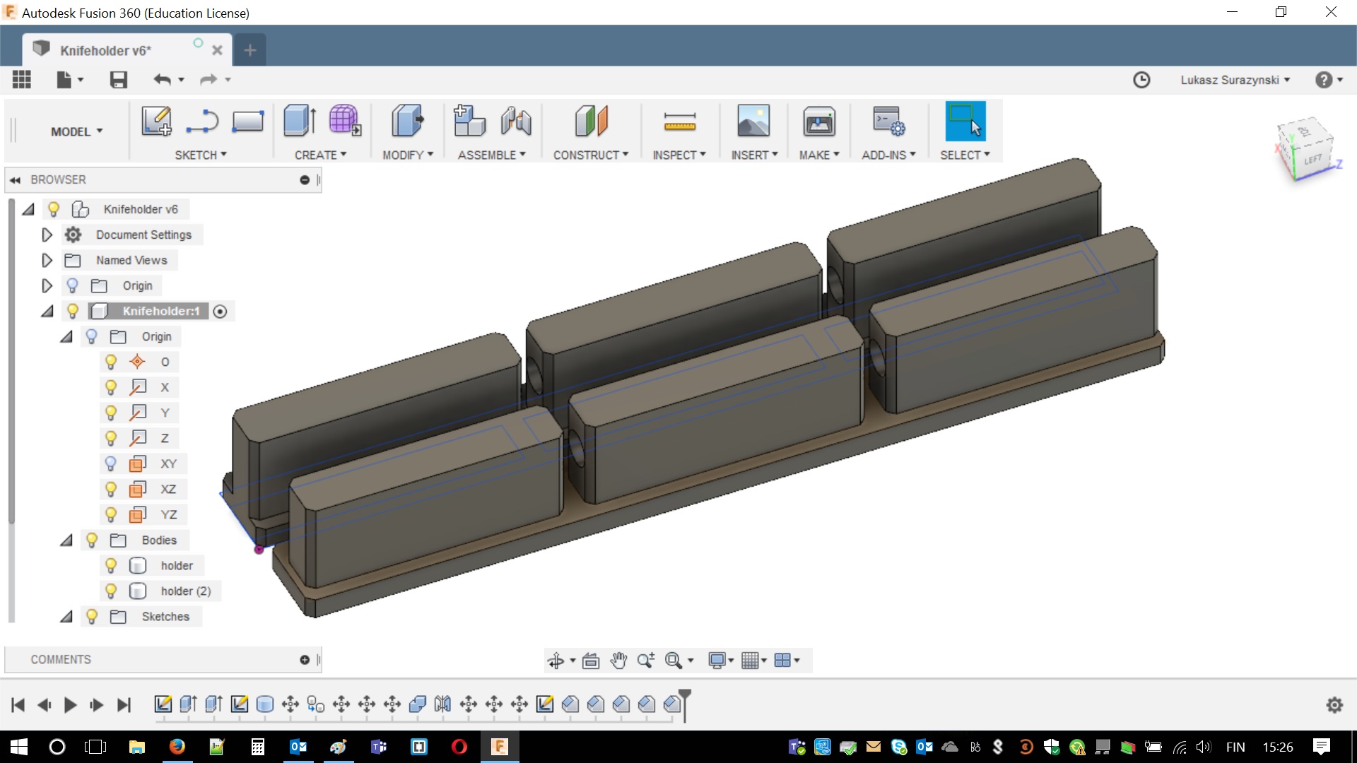
Now time for some science. I placed cylinders on their positions and using MODIFY > COMBINE then I simply subtracted them from relevant piece. That worked surprisingly well and it was fairly simple. Same with mirroring the body. Two screenshots explaining the process are below.
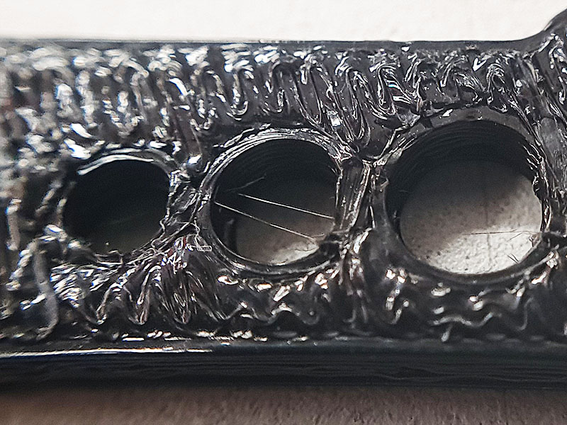
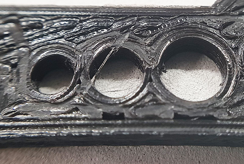
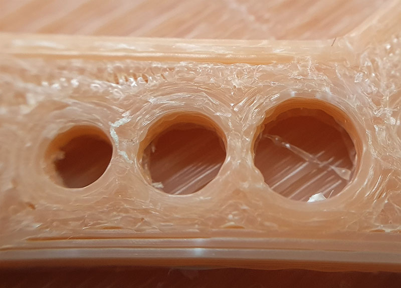
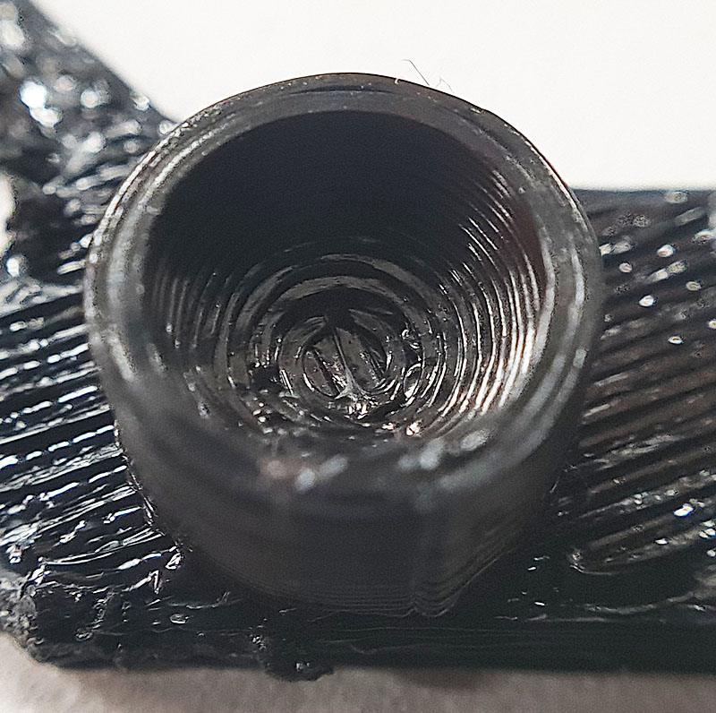
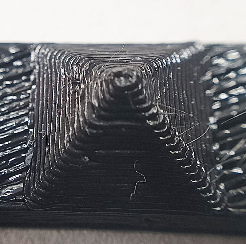
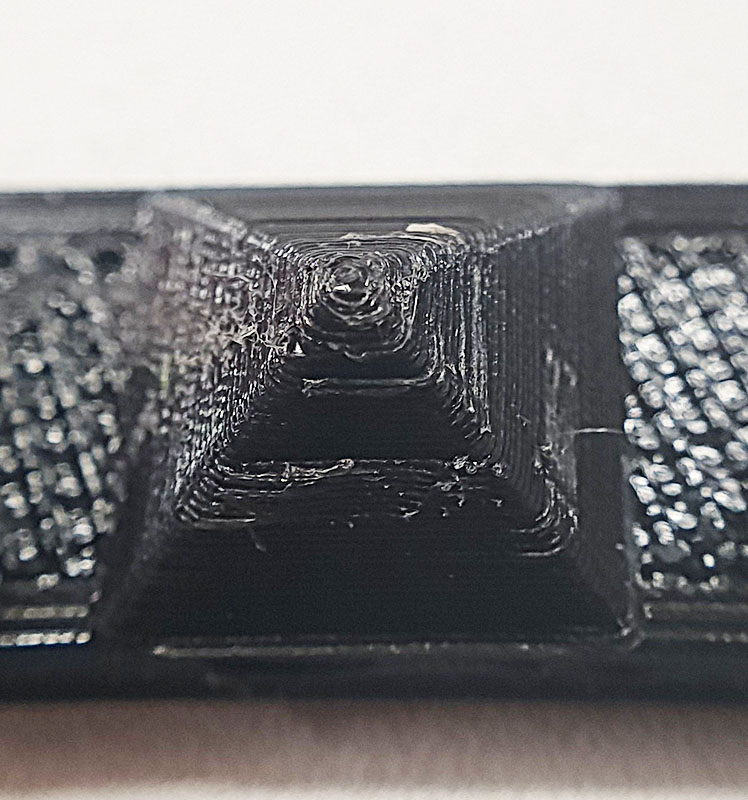
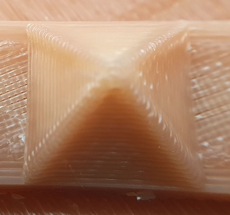
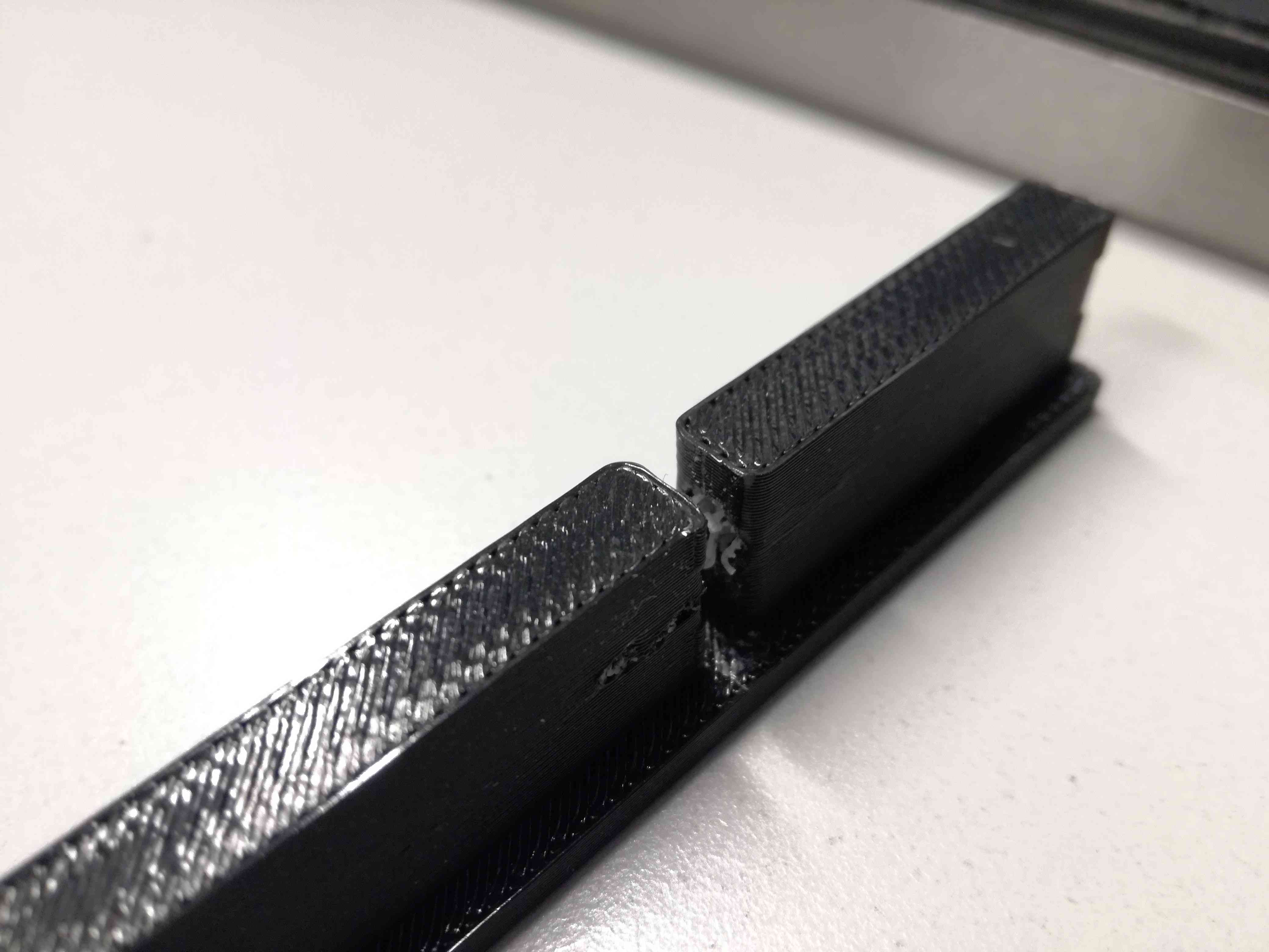
I placed holes in a way that no cutting machine can reach it. It is between two strong walls with gap of couple millimeters. Furthermore, holes are perpendicular to the horizontal plane. Drills are not bending and there are no access to use lathe. Can't touch this!
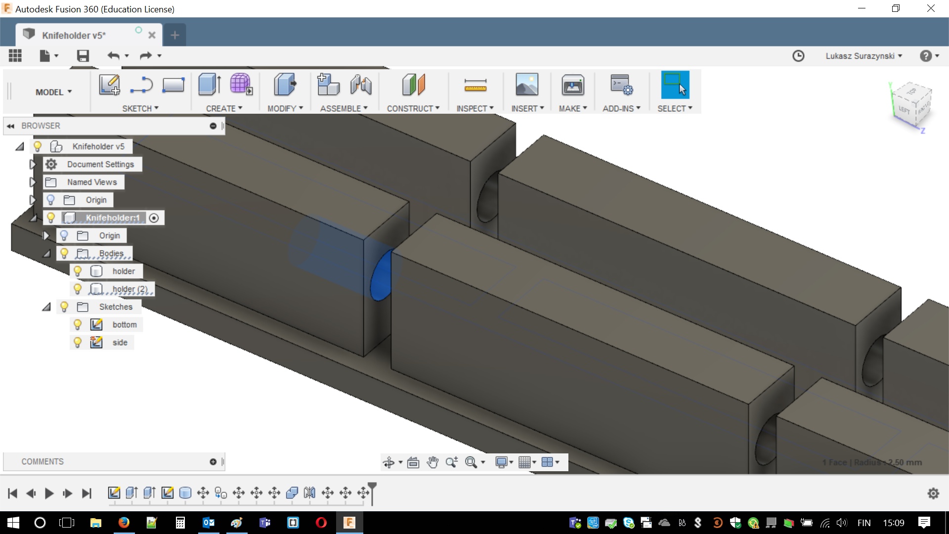
After checking all the numbers, somehow I felt incomplete. I was wondering for so long, why I cannot sleep at nights and food doesn't taste the same anymore. Then I realized that I did not create chamfer on the edges. (I could also prove that I'm cautious on lectures and listening hints! Right. Chamfers are under MODIFY > CHAMFER.
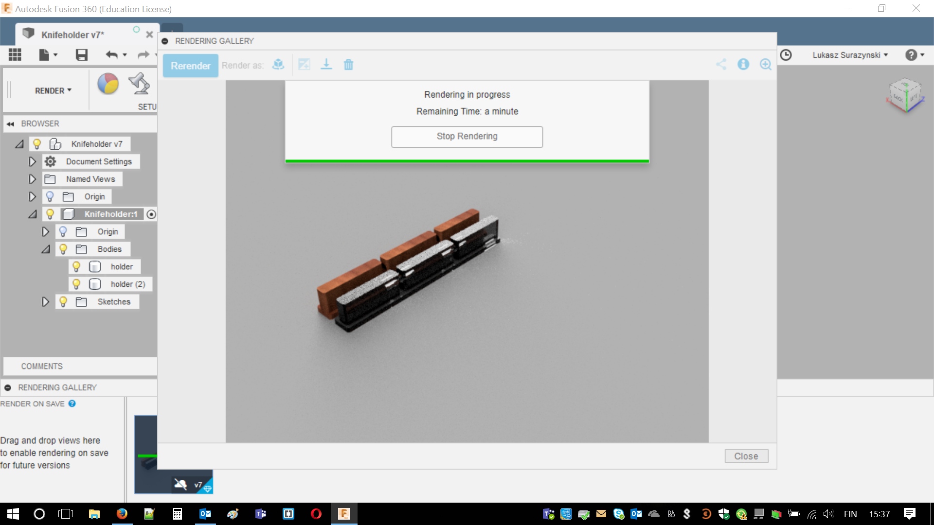
Finally, I could print it out and check if I did not make any mistakes in the design. However, I decided to burn some more electricity. Before exporting .STL I decided to play with my design a bit and rendered it just for fun. Wood and glass was my choices. First attempt took quite long as I chose really big amount of iterations. I believe at this moment I became a bit impatient so I canceled it and start rendering with less steps.
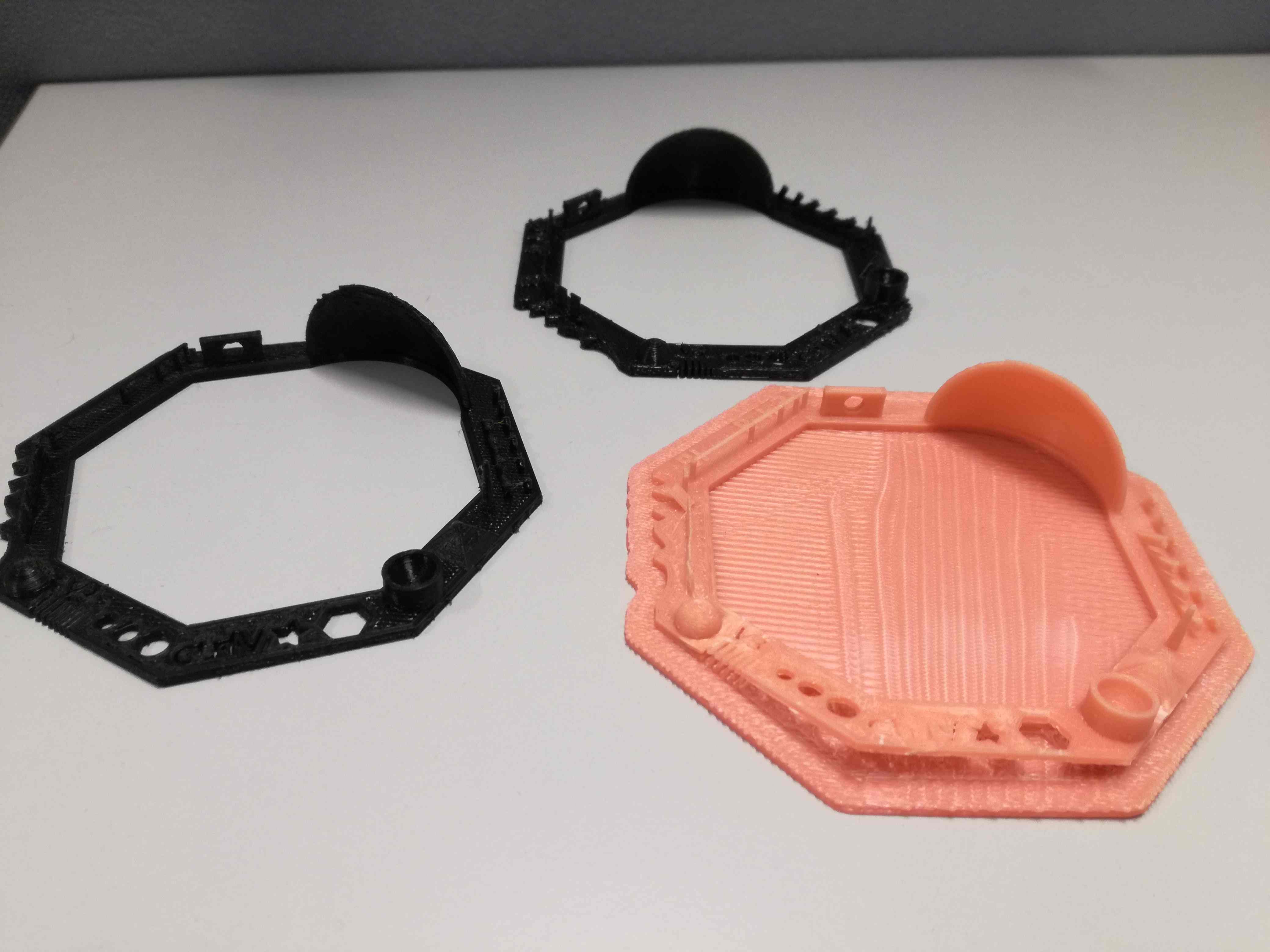
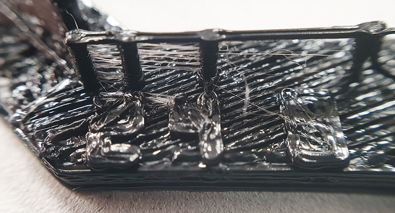
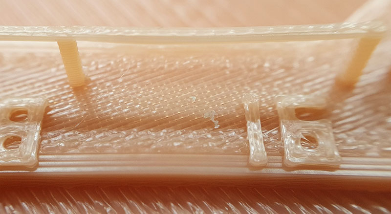
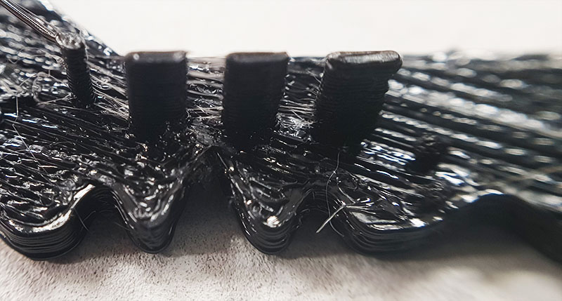
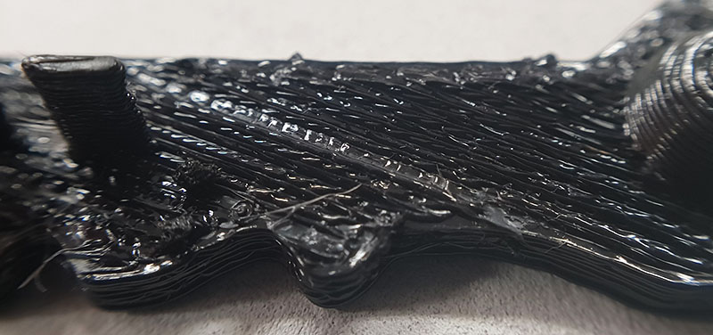
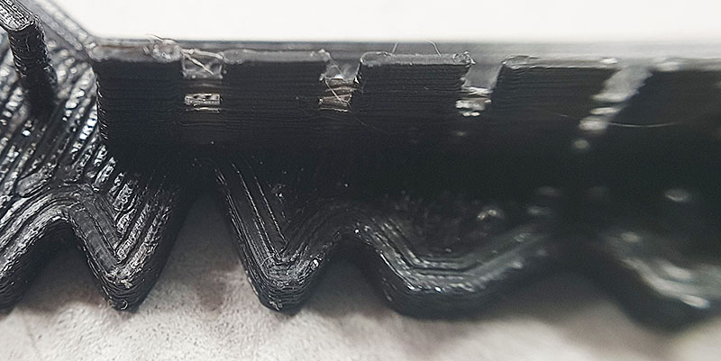
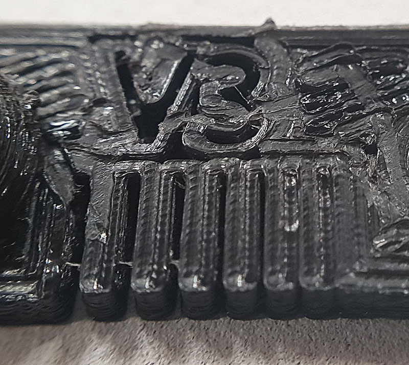
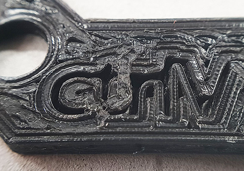
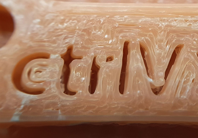
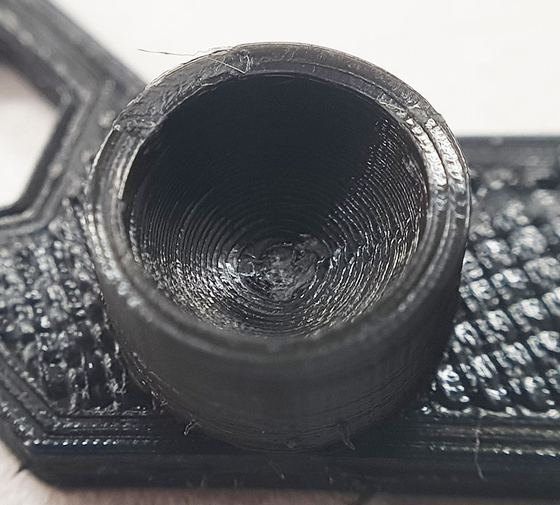
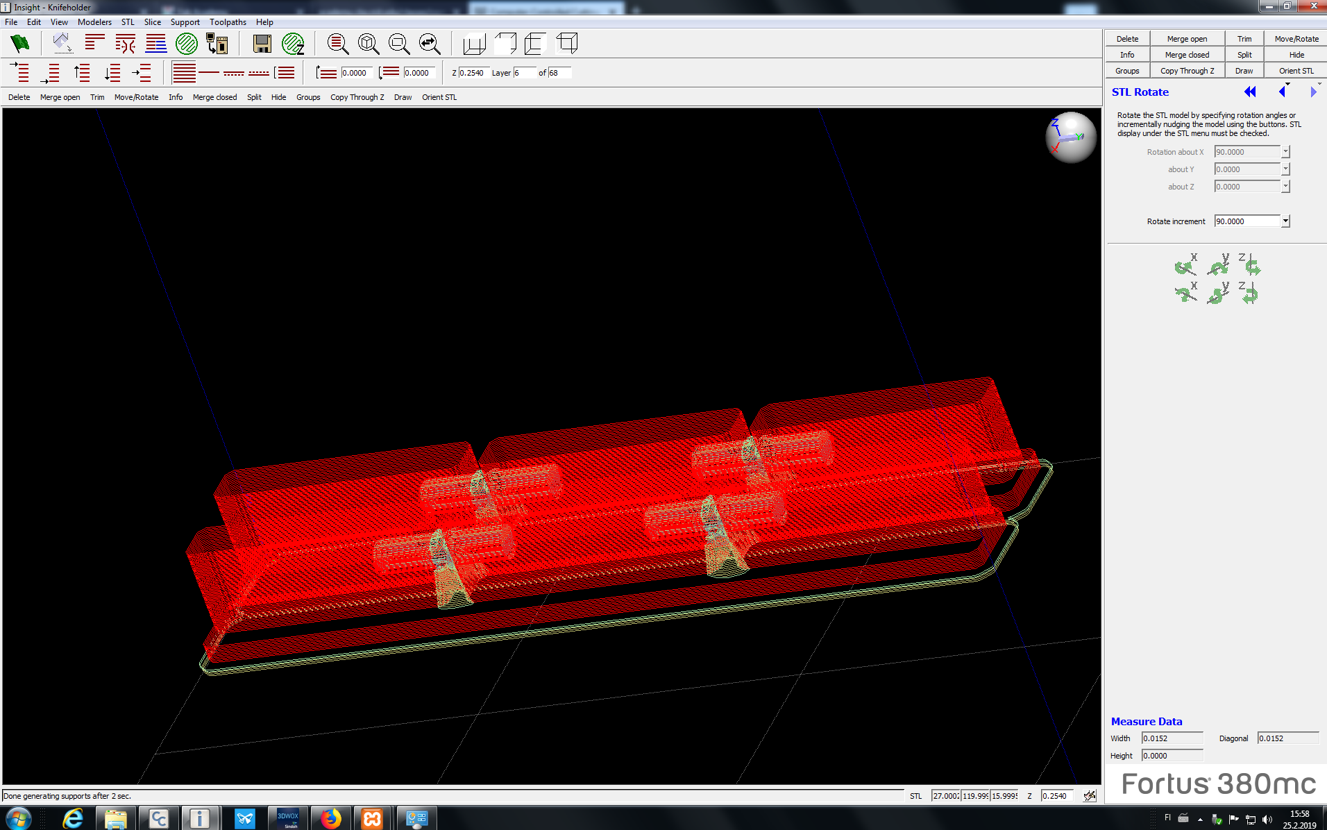
After observing results for a moment I decided to print it. Next step was just simply creating .STL format files and bring it to FabLab. Judging the results from group assignment I shouldn't choose Stratasys but it was unoccupied (and it is also very fast) so I used it for fabrication. I Prepared the file with the required software (Insight). It requires .STL files and allow various operations such as rotating. Most importantly it is adding required supports and exporting file to the printer. I "sliced" my holder with it. At this point I knew I would need support material... and at very same moment I knew I will never remove it from the inner-holes. Simply because I don't really have to. It makes whole piece stronger but it also indicated placement of the holes really nicely. Substrate material is black and supports are white.
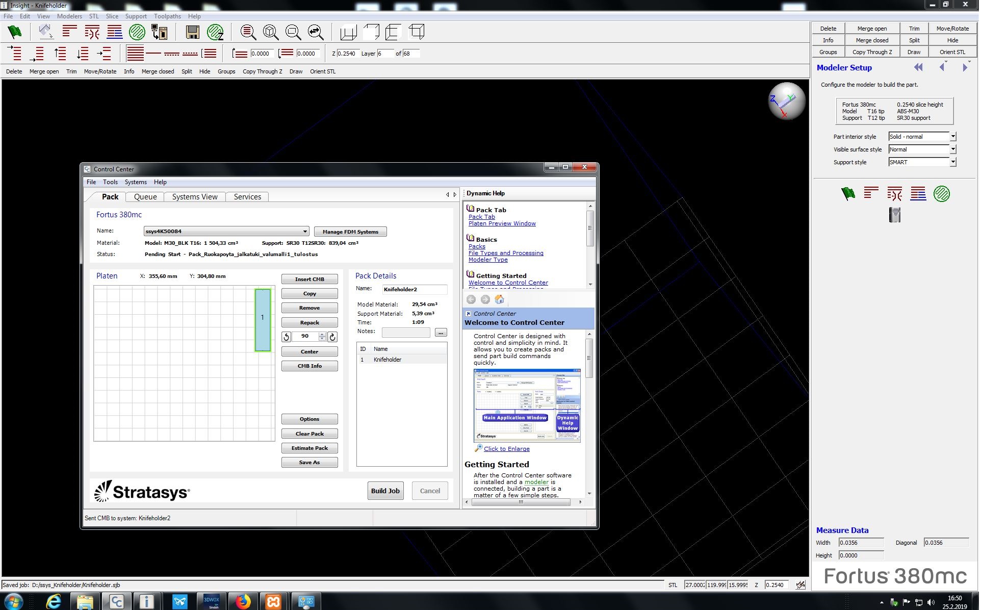
After setting everything with software, I followed below procedure:
- I found unused background sheet (piece of transparent plastic)
- Placed it inside chamber of secrets and preheated it
- Check if background sheet is placed correctly (metal pins)
- Chosen proper file using LCD screen on the right-side and pressed big Play button
Results
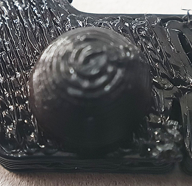
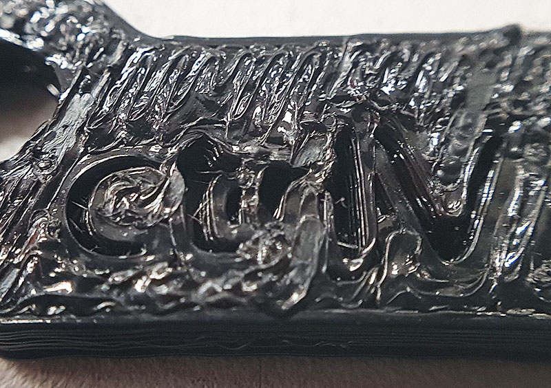
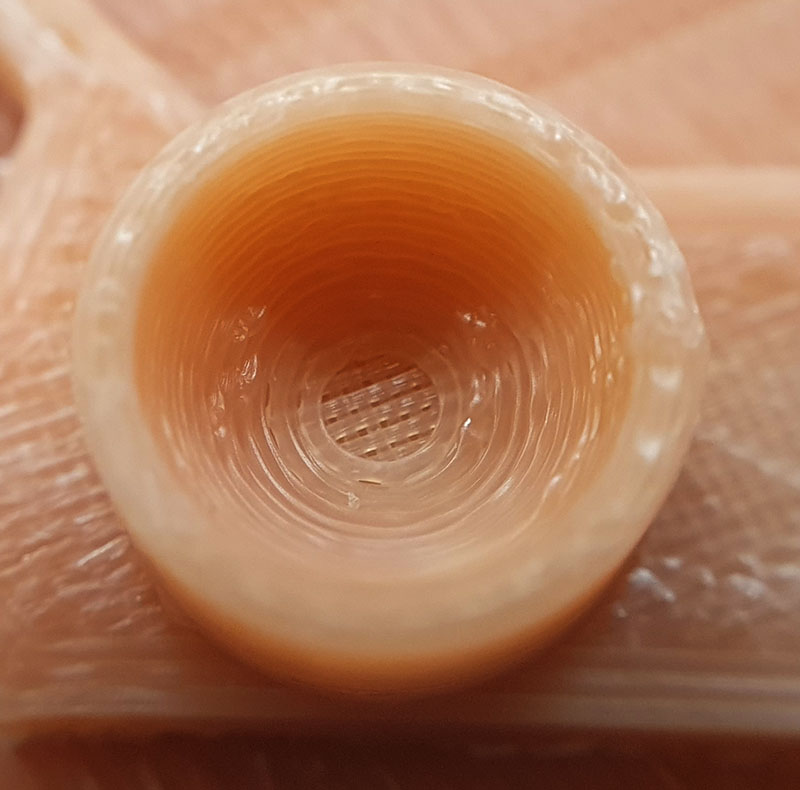
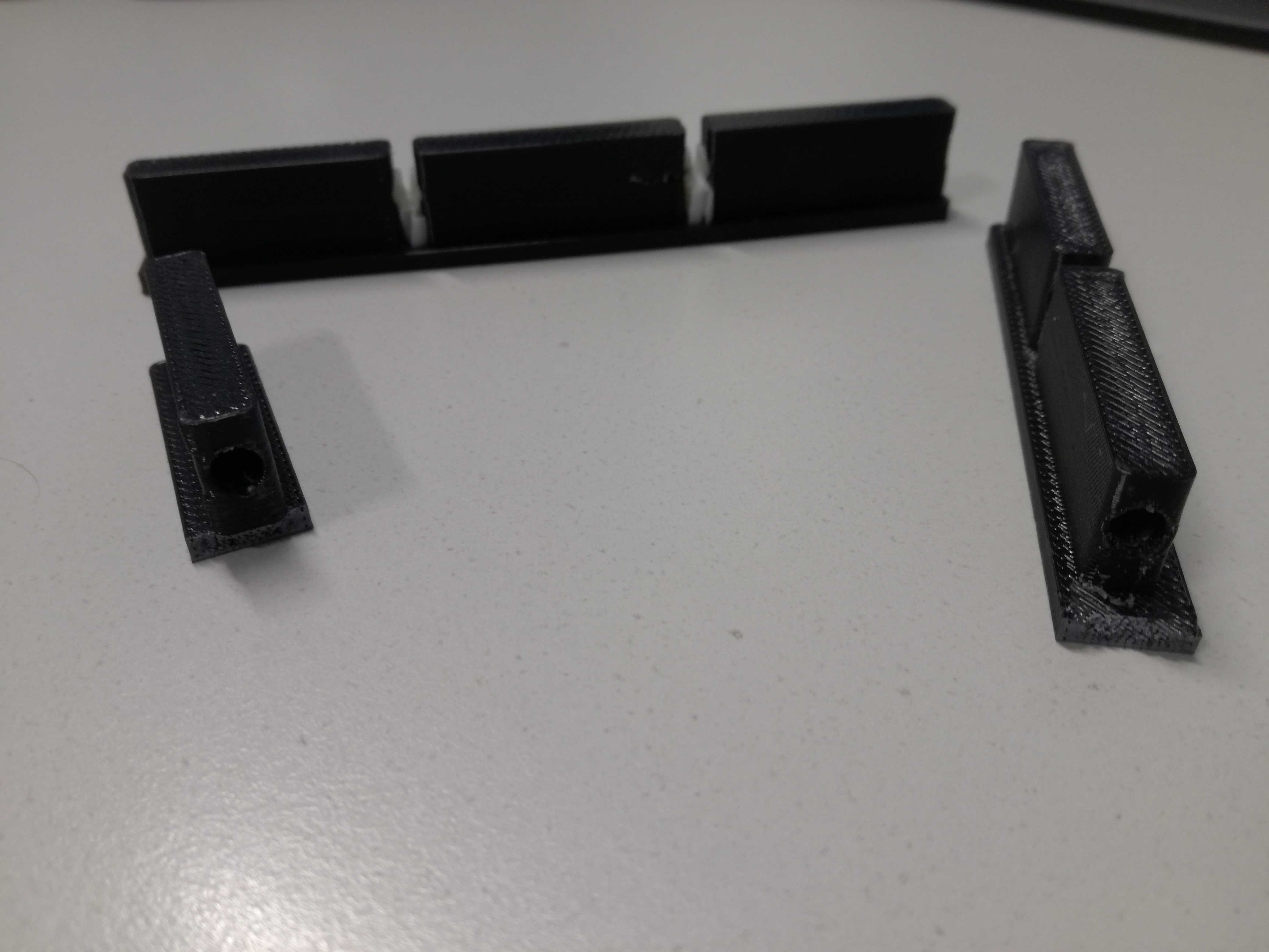
After I took my pieces from the printer I already knew they will fit. They did. I was quite happy as I spent quite some time on measuring my "majestic" knife holder with caliper. Moreover, all this plastic I shaped will have some purpose. After I tried how good they fit I unfortunately broke one piece, while trying to disconnect holder and filling part. It was not that bad as I could show they are really having unreachable horizontal drills. Following pictures are describing the results:
3D Scanning
For scanning purposes I used Sense 3D scanner. It is handhold scanner with its own software, which can be find there: Download:software. Device is able to capture 3D scans of an objects and transferring those into files readable by 3D printers. In other words you are able to print out things, which you scanned...
... and you are expecting that you can have two similar things, e.g. clone your friends (if you have any). Unfortunately it still cannot copy souls. Alright, sarcasm mode off.
In general there are minor and major issues. Details are usually missing, sometimes software is also confusing origin points and your scans are monster-like. Moreover, reality looks totally different than videos (just below), if you are capturing by hand you will never get results same as achieved on YouTube. Most likely you won't be even close. Because of all those factors I consider it more as a toy rather than real 3D scanning tool. Hopefully, they cannot afford assassins for such poor review.
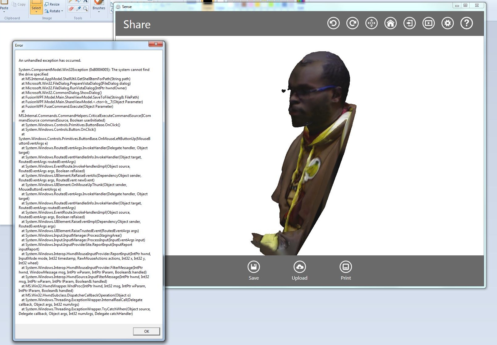
Here is the result from my personal scan. I followed procedure from above photo. My test "object" was Michael, fellow student. Unfortunately I cannot put any files as it was impossible to save it on the desktop. Error code is attached on the photo.
As I mentioned there were plenty of issues, while trying to scan the object. There is major influence of illumination, distance between object and scanner, steadiness of scanner, even rotation of the object, speed of scanning. All of those factors should be taken into account in order to get some decent result. Furthermore, object cannot be same color as background. Still small details of the object are lost, e.g. sandpaper and glass would look as same texture.
Probably biggest problem was issue with the scanner' software as I could not save files. In general I disliked the process. Hopefully, technology will be continuously developed and improved. Future generations of Fab Academy will have easier life.
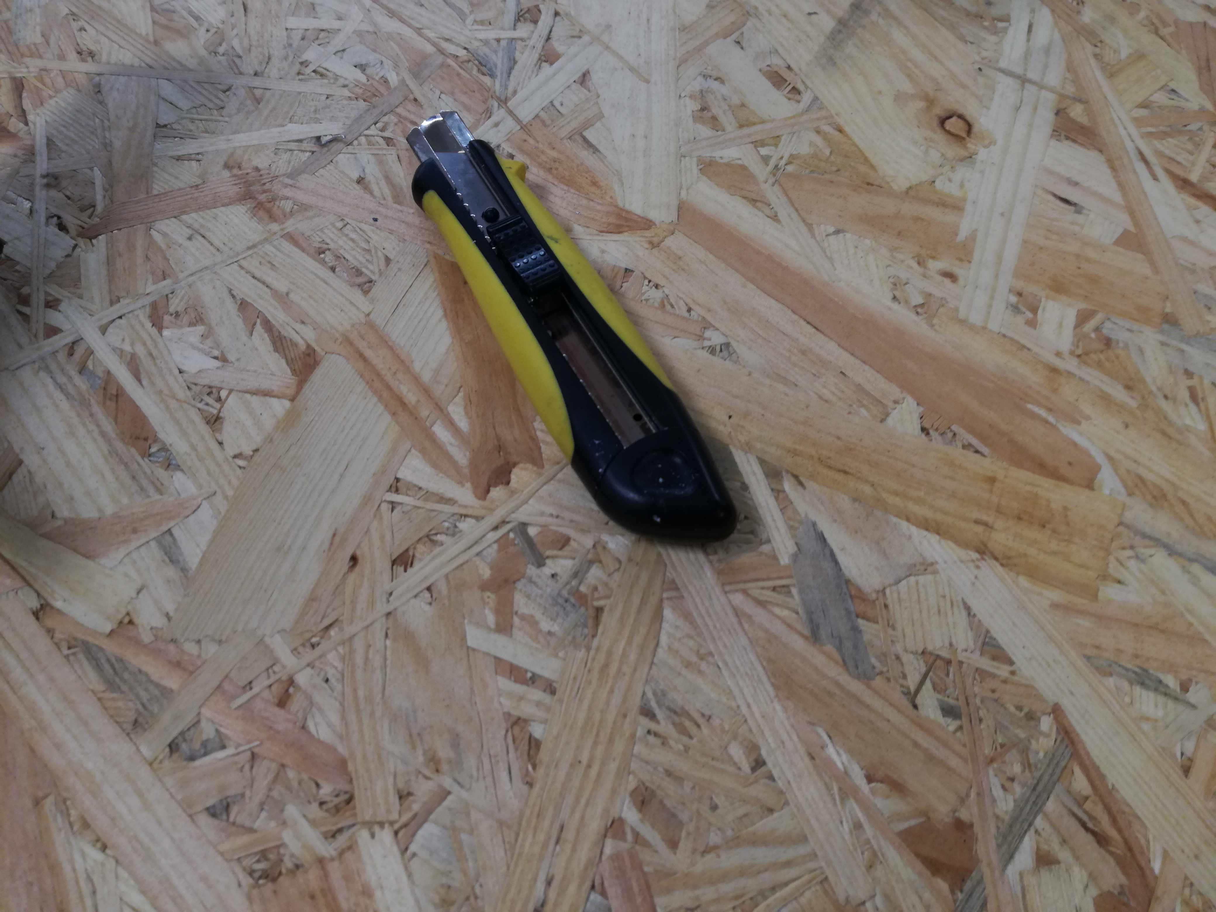
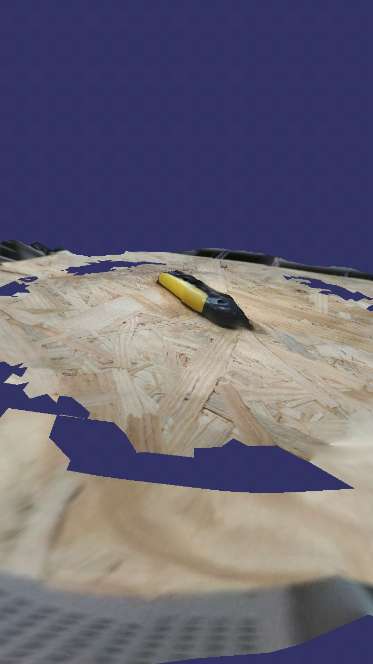
This is how I ended up with Scann3D. This is phone app, which allows to scan object and save files (in first three days of free trial). There was no time to loose since I need to save at least .STL that 3D printer may read. I took first thing, which I found - a paper knife.
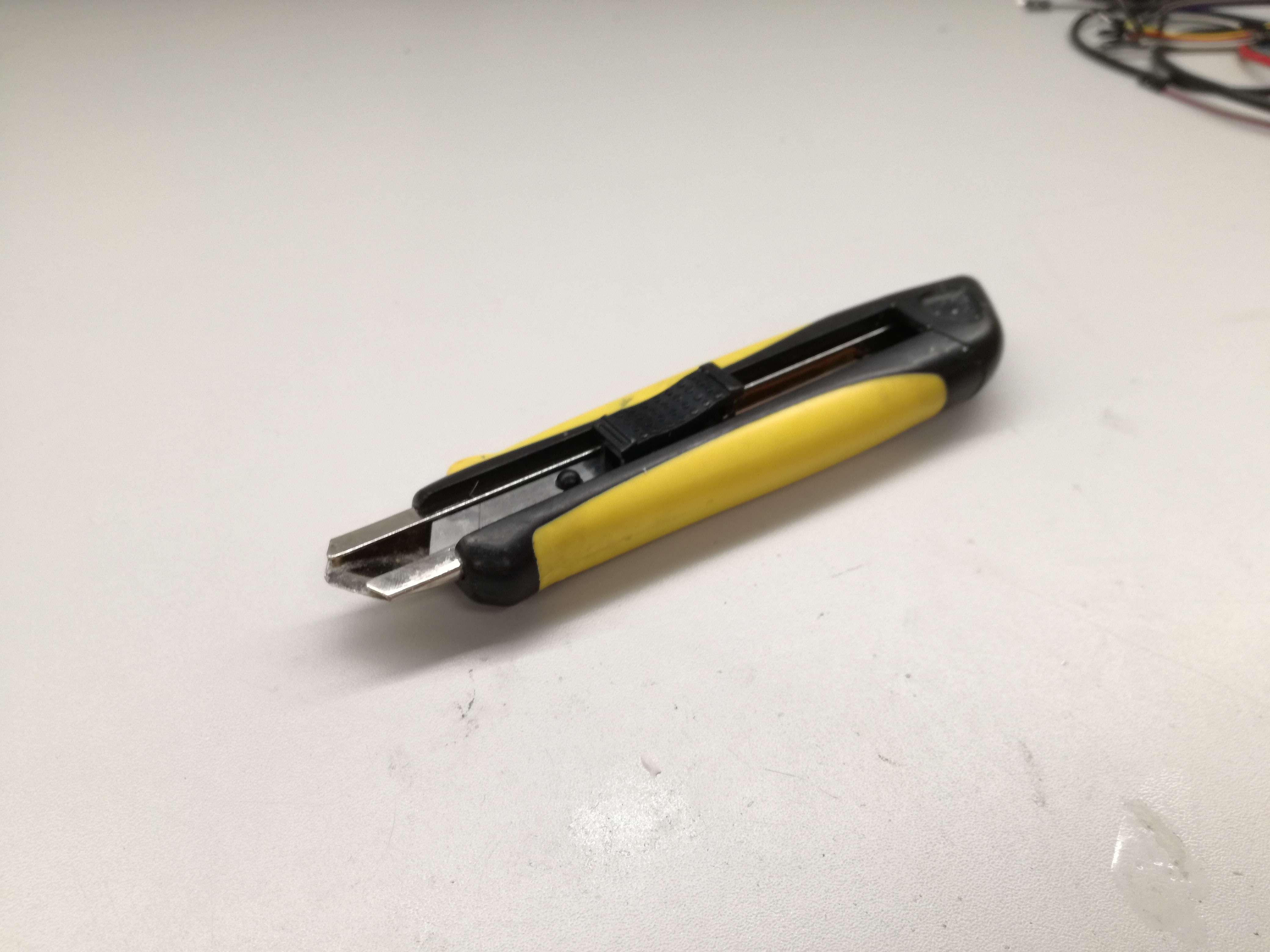
I simply placed it on the wooden table with easy access around. Fixed phone using some soldering handler and made 55 photos rotating the phone around. I had to pay attention to green/yellow/red dots, which were indicating tracked points. Green means good as usually. Motion has to be slow and even, whole object has to be on the screen. I had no issues with focus.
I guess I would not be able to stab anyone with my scan but still I'm happy with that after a little failure with previous device. Scanning was fairly simple, I only had to pay attention to small steps with phone. Ah, also stability. Rendering time took around 10 minutes.
Files:
Download: Knife holder filesDownload: Paper knife (3D scan)