Week 14: Networking and communications
I have to admit, I had fun with this week assignment. Firstly I was a bit frightened because I could not make my ATTiny "talking" trough serial interface. Serial communication was obvious choice as all my microcontrollers are already prepared to use this interface (using FTDI cable).
As introduction I will use old, good auntie Wikipedia: In telecommunication and data transmission, serial communication is the process of sending data one bit at a time, sequentially, over a communication channel or computer bus. This is in contrast to parallel communication, where several bits are sent as a whole, on a link with several parallel channels.
There are quite many others way to make devices "talking", Bluetooth, Zigbee, Wi-Fi, I2C, IRDA are other standards worthy to mention. I think I'm mentioning those just to show some respect to other solutions.

Group Assignment
Team: Handful of people
Four boards were used as separate nodes. Those were connected using serial port, where Jobin's Node (number 1) was used as Master/Receiver. There was Bluetooth mode attached to it. The code may be found on Jobin's page: CLICK. There were plenty of people with their boards, couple the chosen ones connected. We named the nodes as Jobin_Node1, Sahan_Node2, Mikael_ Node3 and Yasir_Node4. All the boards we programmed and connected in series, and controlled through Bluetooth application.
Target was to blink the LEDs on the boards when a button on the Bluetooth mobile application (Bluetooth Control Lamp) is pressed. The LED on each board lit up when the number corresponding to the number assigned to the node was pressed. Finally, the code was modified so that all the LEDs turned on and off at the same time.
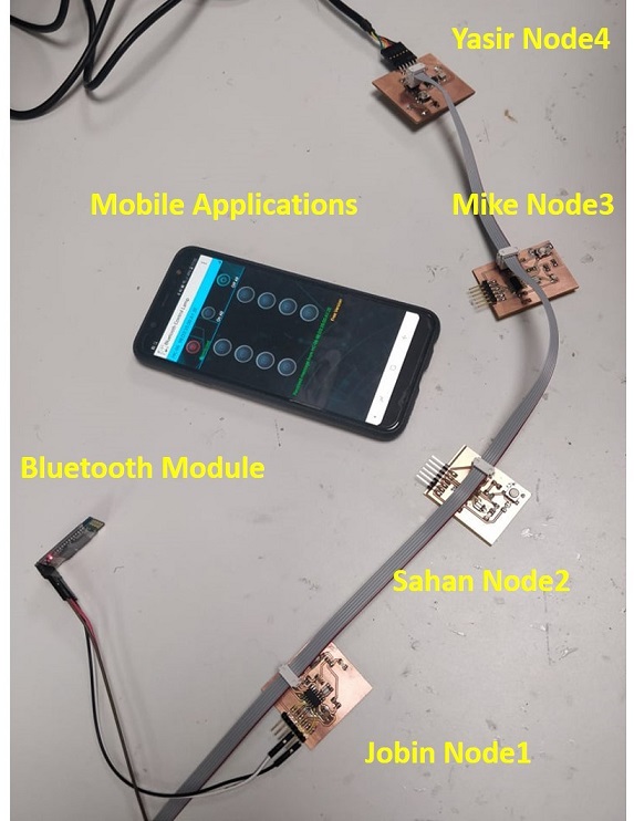
We have documented our connection by photo (above). There is also movie (below) presenting, how things works.
Individual Assignment
Concept
Let's move on. Instructions for this week are: design, build and connect wired or wireless node(s) with network or bus addresses. My way is to use previously made boards, namely Helloworld.pcb and TARSMotherboard.pcb and connect them using serial interface. As I tested before that two boards are working well, there shouldn't be any problems. but there were just one, so please check Troubleshooting section in the end of this web page. After one little issue was solved, there were no problems.
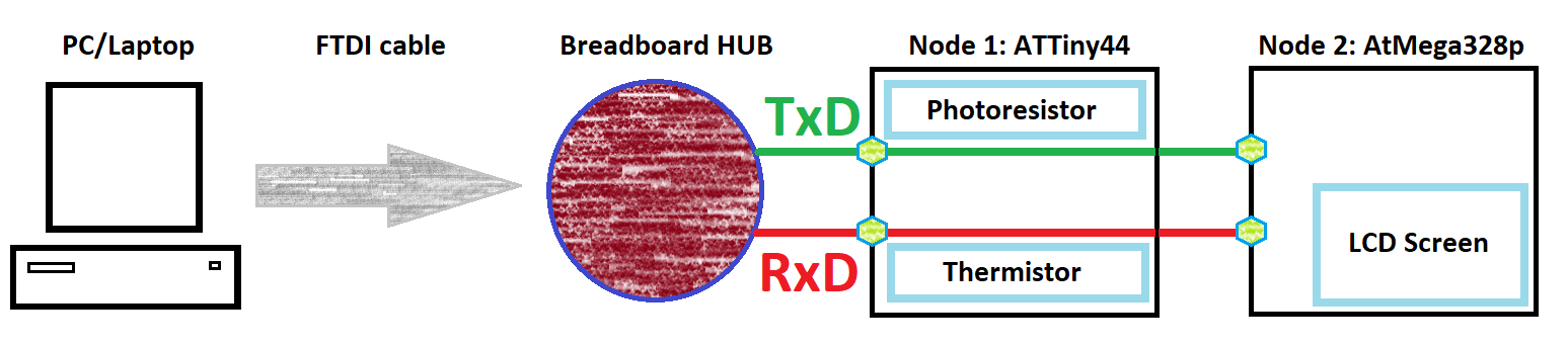
In general serial transmission requires just two wires/connections. TxD and RxD are marked in every single microcontroller's datasheets. Especially those, which has this serial transmission feature.. In my case I will use FTDI cable to create USB to Serial translation. PC/Laptop is Master and it is used to call two nodes based on ATTiny44 and ATMega328p. Node1 (ATTiny) is connected to photoresistor and thermistor, which were designed in Input devices week. On the other hand Node2 (ATMega328p) is connected with LCD screen, which was designed in Input devices week. It means I used both Input and Output devices and read/write values using serial communication. Idea of connection is presented below.
Prototyping
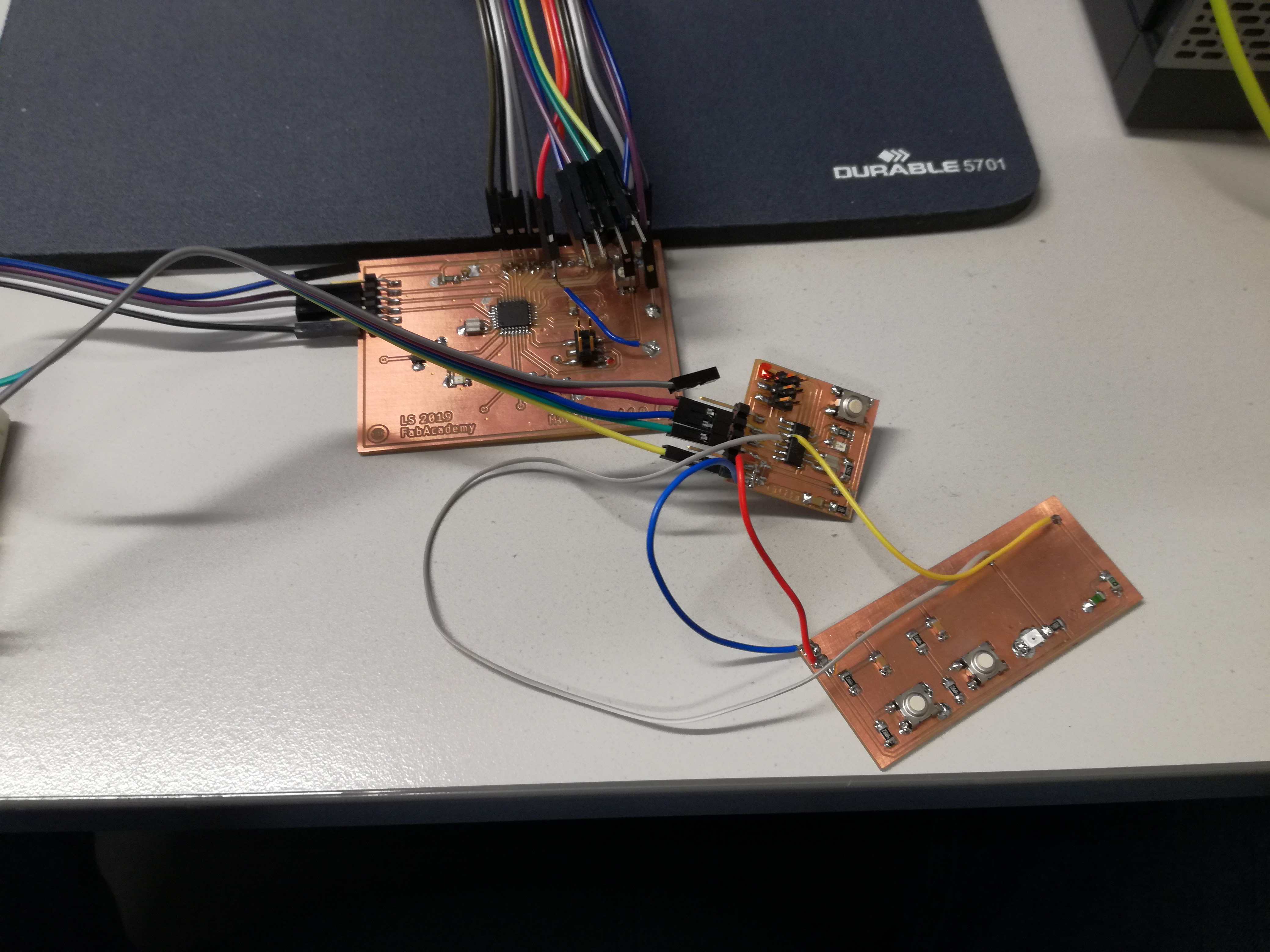
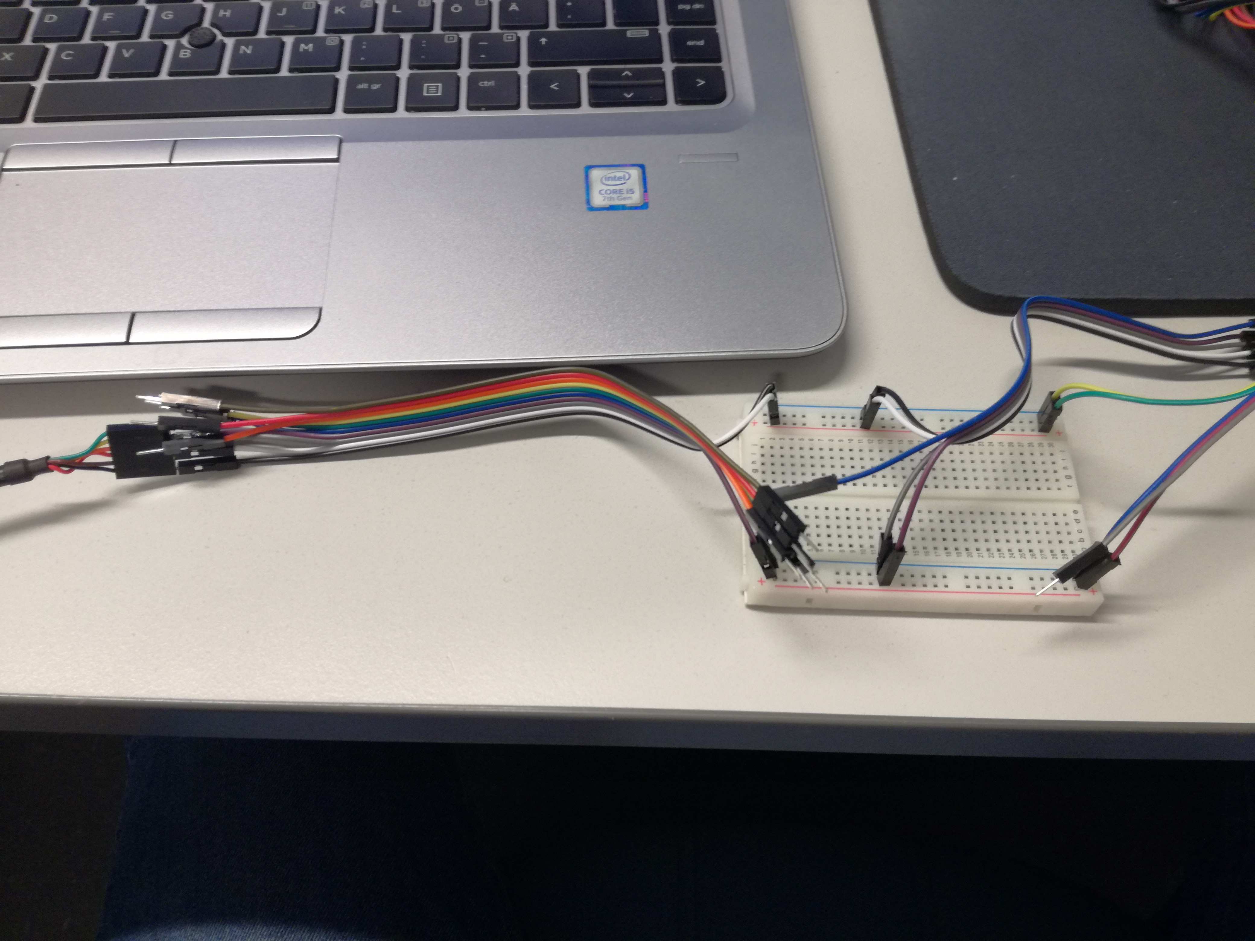
Now, I can present a little bit of wiring. As in all prototypes connections are a bit unsorted but those were triple checked before connecting power wires. No animals or integrated circuits were harmed during this week's assignment.
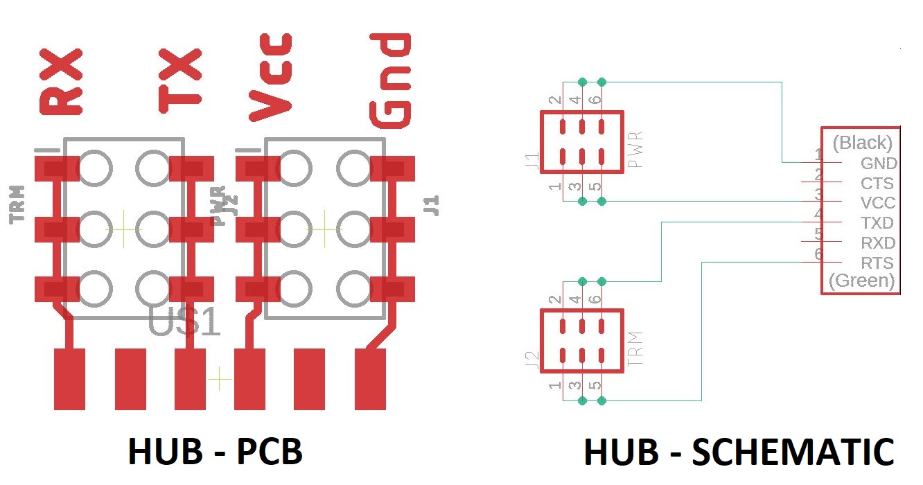
This is time to introduce a concept of HUB. As everything requires two lines in order to "talk". I had this idea to create some sort of a HUB, which would connect everything. I designed it in Eagle. PCB was ready to be milled and soldered. In the end, I realized that it is not needed. There was literally no point to waste materials for something, which will be used just once.
So I decided to use breadboard and couple wires. Exactly 2 x 4 flat cable connectors. There were plenty of those in our FabLab.
Programming
This time I was in a mood for experiments so I used CoolTerm, which may be downloaded from THIS LINK. It is a bit more convenient than built-in Arduino Serial Monitor and much more convenient than Putty, which is simple and has to be adjusted every time it is turned off. I recommend this to everyone. Actually, Gleb shown Coolterm to me. I'm grateful.
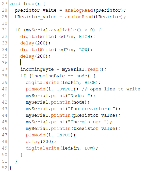
Next step was a little bit of programming. Arduino IDE was nice solution as it had library for both LCD screens and Serial communication. Firstly, ATTiny code. Node is constantly reading values of both photoresistor and thermistor. It is also waiting for incoming serial transmission. Every time Node 1 is called, it is responding with answering the call by giving node's name. Then Red LED is blinking and in the end values of both sensors are transmitted over serial interface. In the end node is ready for next call.
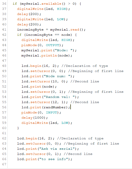
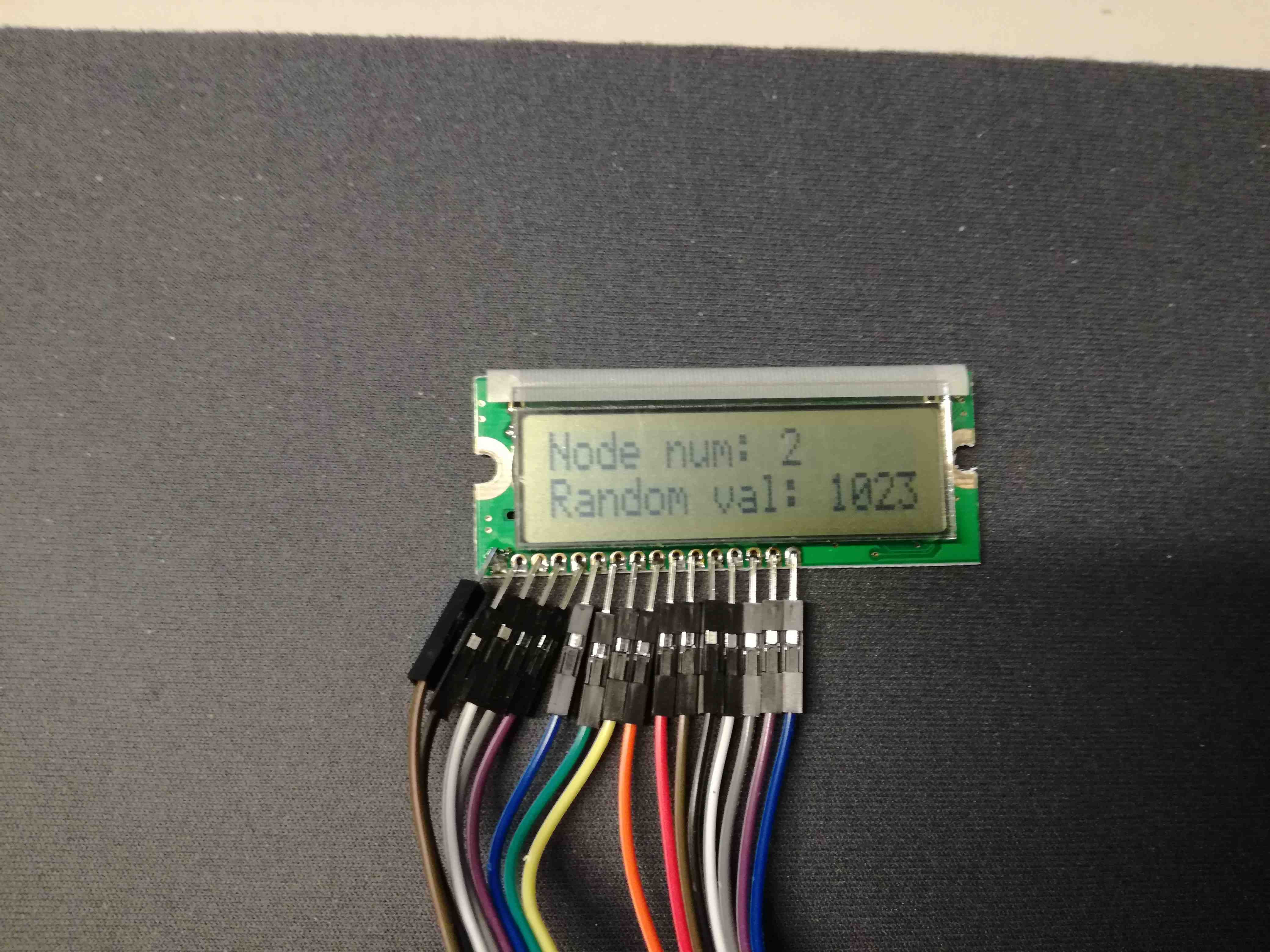
ATMega has a bit longer code. Nevertheless it is very similar. It also waits to be called. If this situation occurs then couple steps are done. Firstly it flash LED, then answers on the call by writing node's name. After that information about node status is presented on LCD along with some random value (generate by pseudo random generator). Then after couple seconds it return to waiting for another call.
Final result
Let's check how does it look in terminal. Once again I have to acknowledge CoolTerm for really simple and efficient design and usability.
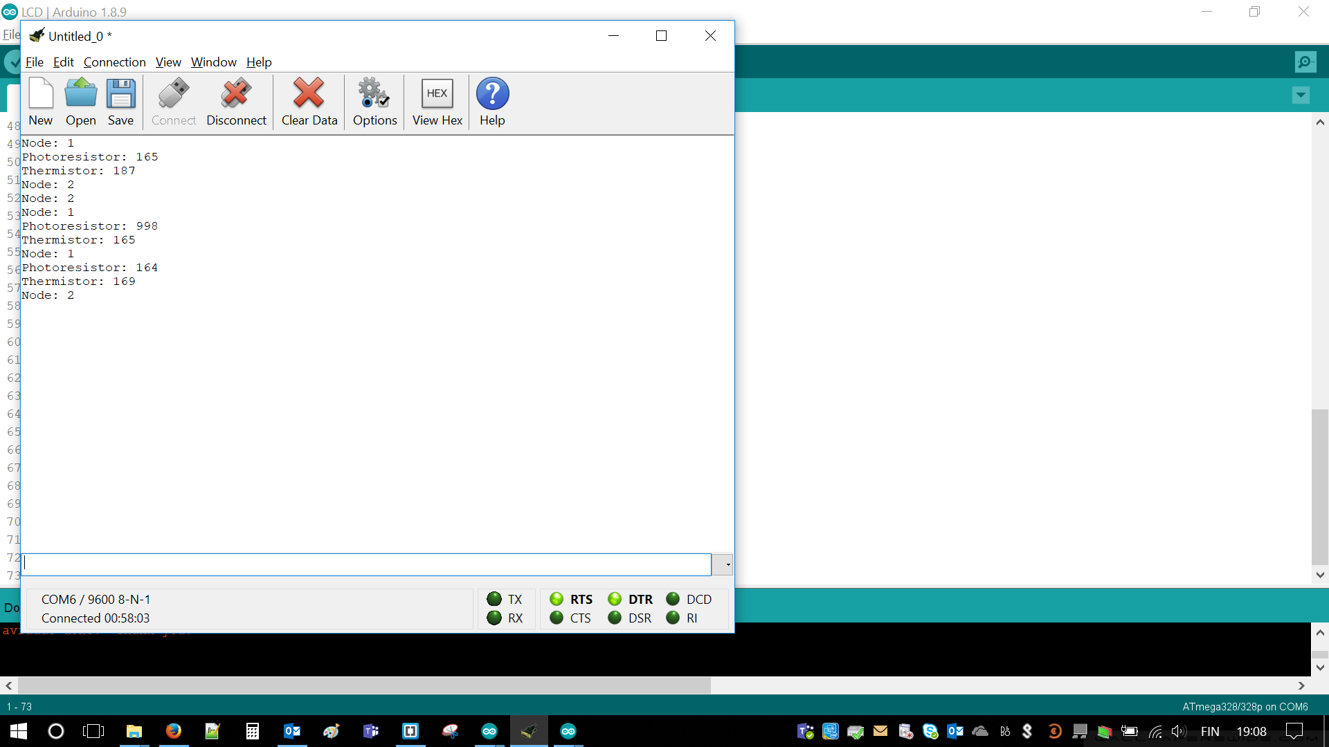
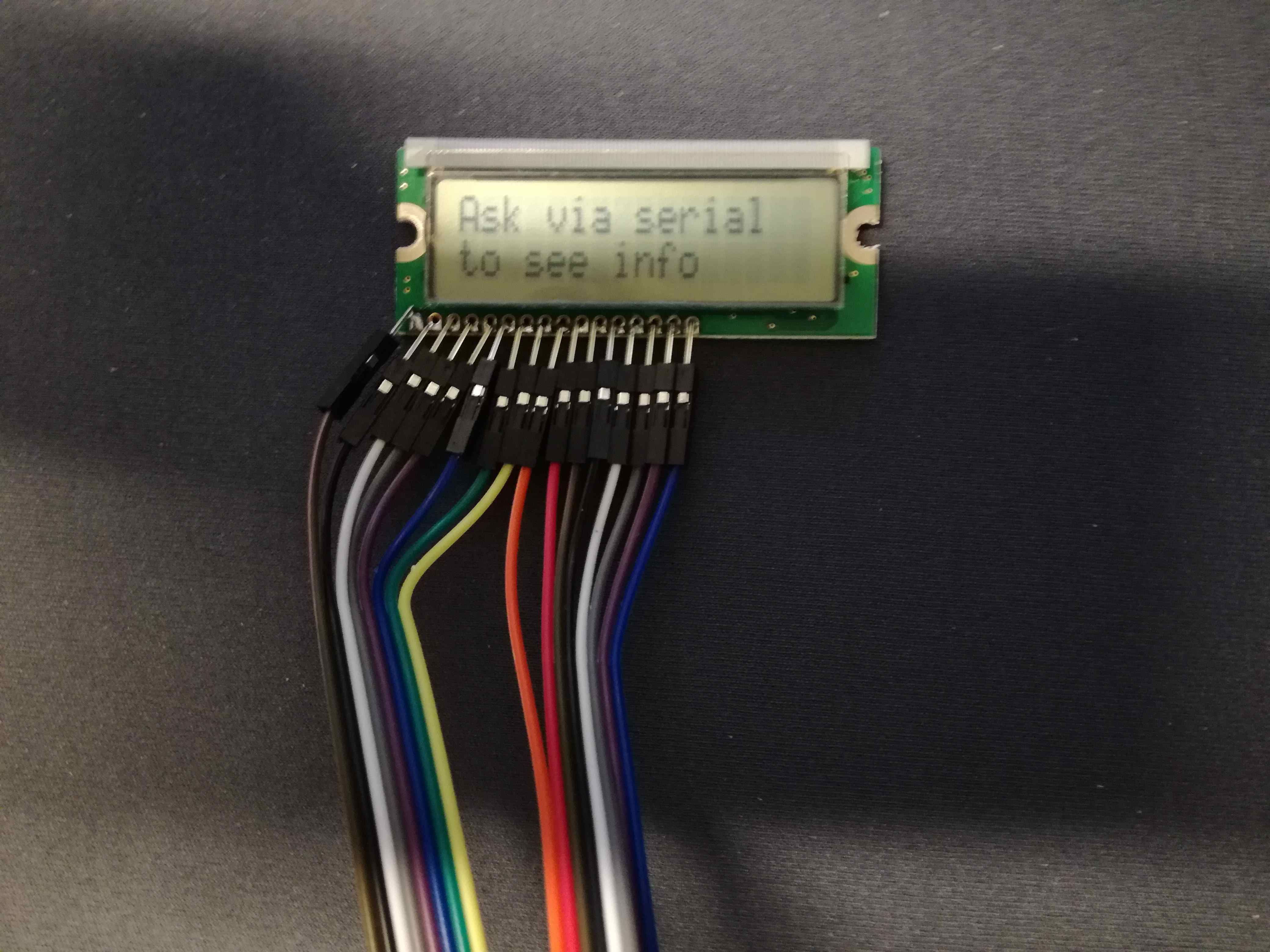
Upcoming two photos are visualizations how LCD screen responds for call.
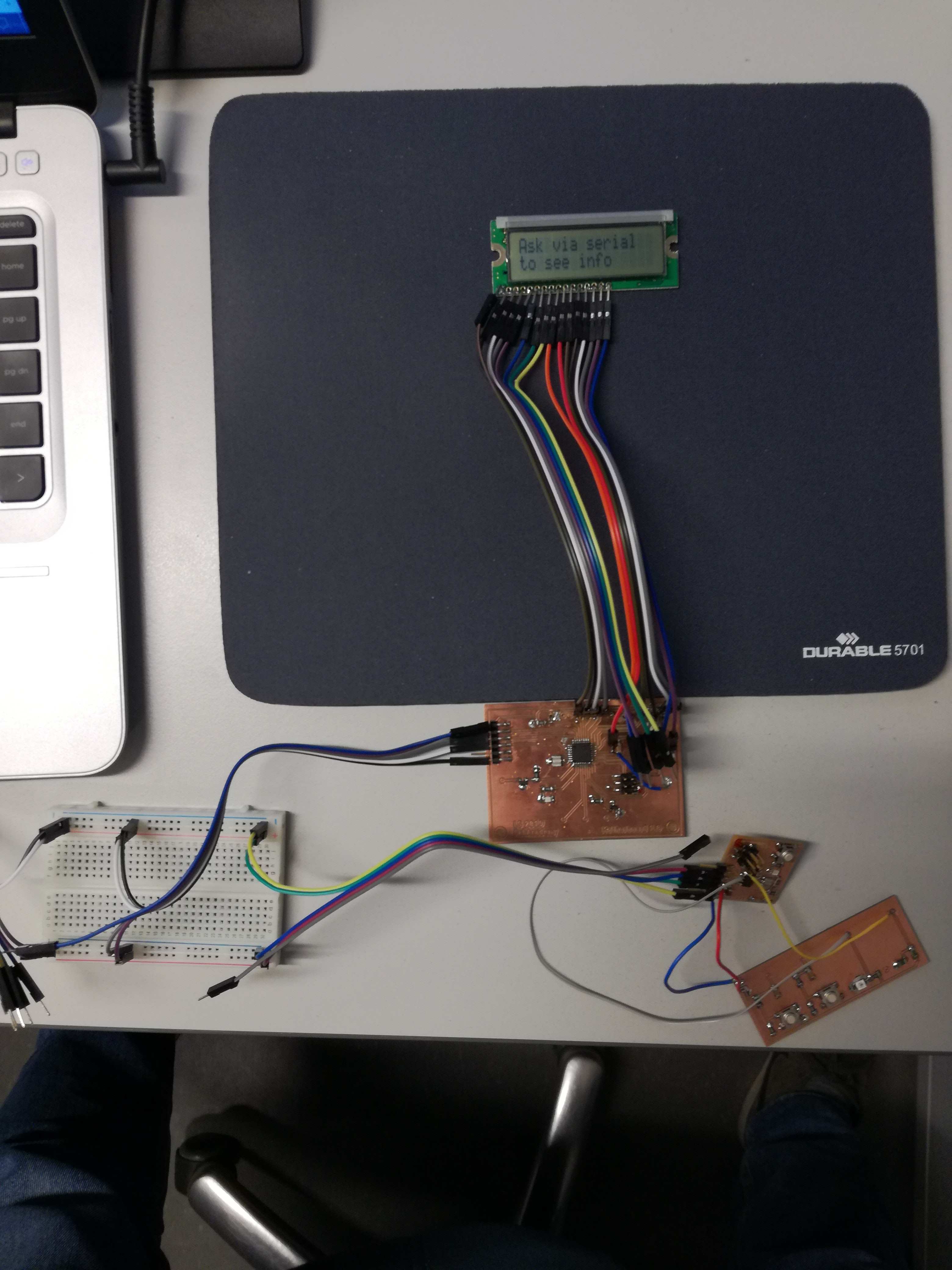
Time for the last image or so-called hero shot. Whole setup visible. Proof that I designed it, my leg in the background.
This is not end of surprises. I managed to record video of my setup. There are all features visible. Moreover, there is answer on the call presented. Firstly Node 2 is answering by prolonged blinking. Then Node 1 is performing same operation. Nevertheless, it is a bit shorted than with previous node. In the beginning both of them are blinking as a sign of receiving serial transmission.
Troubleshooting
Troubleshooting or part, which every designer likes most. I have to say just couple words. In order to create reliable connection via serial port both microcontrollers has to work with something better than internal clock of 1 [MHz]. Most likely 8 [MHz] is already enough. However, I'm only suspecting as I used 20 [MHz] resonators and those are for sure good enough.
Finally, if you connected your crystal/resonator/RC circuit and still your nodes are not working. There is just simple solution. BURN BOOTLOADER! As simple as that, you are welcome - my future follower.
Files
ATTiny44 Serial CodeATMega328p Serial Code