Week 4: Computer controlled cutting
There are two kind of laser cutters in Oulu's Fablab. First and bigger in terms of size is Epilog Fusion M2 40 Laser and second one is her smaller sister Epilog mini. The documentation may be found under this LINK. In my case I decided to use first device. Usually the bigger the better, unless you are trying to park your huge car in the old town of Krakow :)

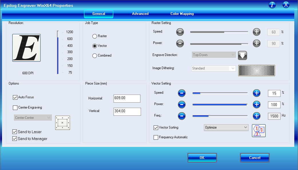
When planning some laser cutting it is important to familiarize with one particular table, which may be found in documentation. It precisely characterize crucial values such as speed, power, speed on given DPI for each material. Focus should be adjusted with special triangle-like tool. Table may be found below. We have used standard values for both materials (MDF and acrylic).

Position of the laser tip, height of laser tip may be adjusted manually. Every other parameter is adjustable with software. In most of cases (known materials) it is enough to choose proper material and its thickness and load preset values. Nevertheless, there is always space for adjustments. How those parameters are influencing cutting I will explain a bit further.
Group Assignment
The dreamteam: Gleb, Marjo, Perttu and me
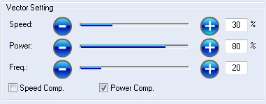
Let's start from investigating how laser power and speed of the head affect cutting. For this purpose we will use 3 mm thick MDF board. Just couple shapes, rectangle and circle will be enough. Firstly we will use FabLab predefined values and compare them to their changed versions.
 |
Cut through |
 |
Failed to cut |
 |
Failed to cut |
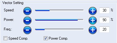 |
Failed to cut |
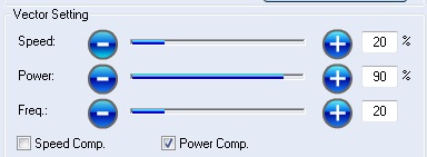 |
Failed to cut |
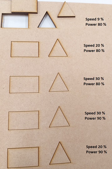
As we noticed, speed and power are very important factors. We failed to cut MDF with our own values. Because of that we just decided to use predefined values for the materials in the future. We will save both time and material in future. Kerf calculations will be performed for predefined values for each material.
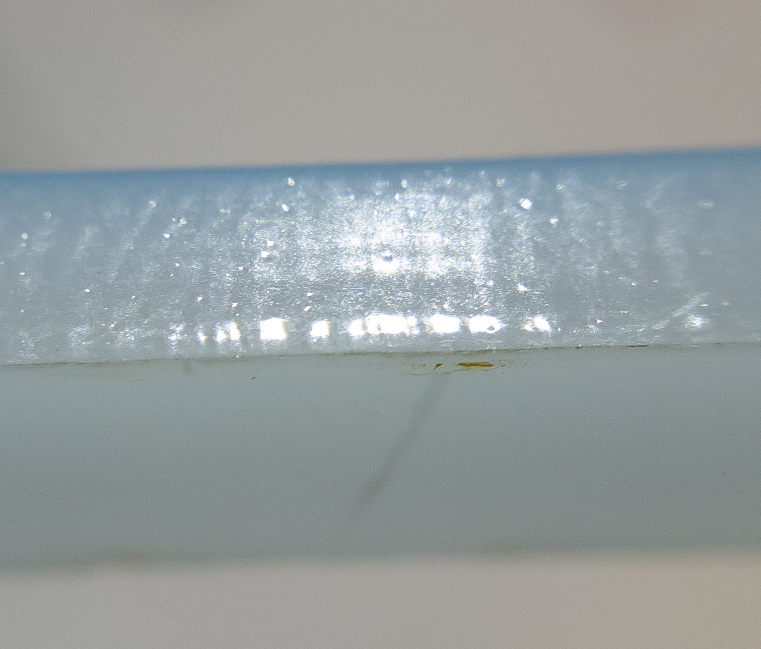
Before we will begin measuring it, we should understand what "Kerf" is. Definition is fairly simple. Kerf is a slit or notch made by a saw or cutting torch.
What does it mean? Kerf is just a term to describe reality. Everything in real world has some dimensions. There are no infinitely small lines. Cutting elements have some width and if you won't pay attention to it for sure your elements won't match. It means from the 'inside lines' you should subtract this value and from 'outside shapes' you should add kerf. Okay, we got it now.
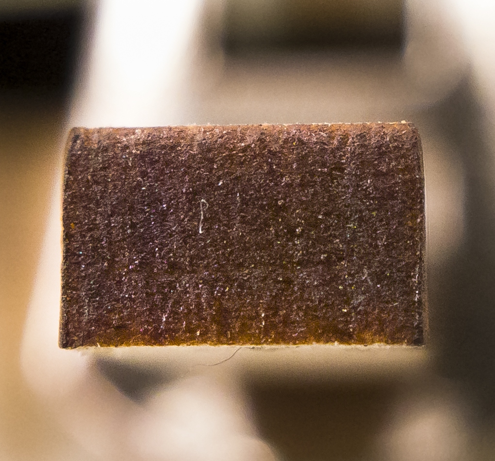
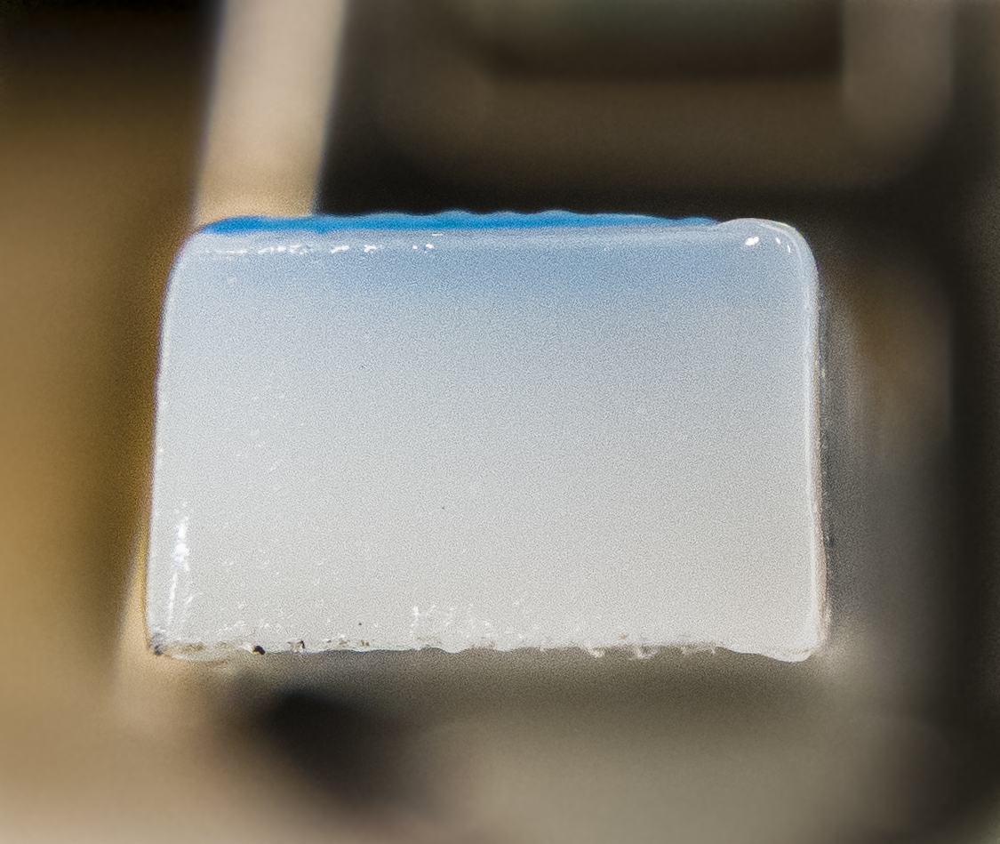
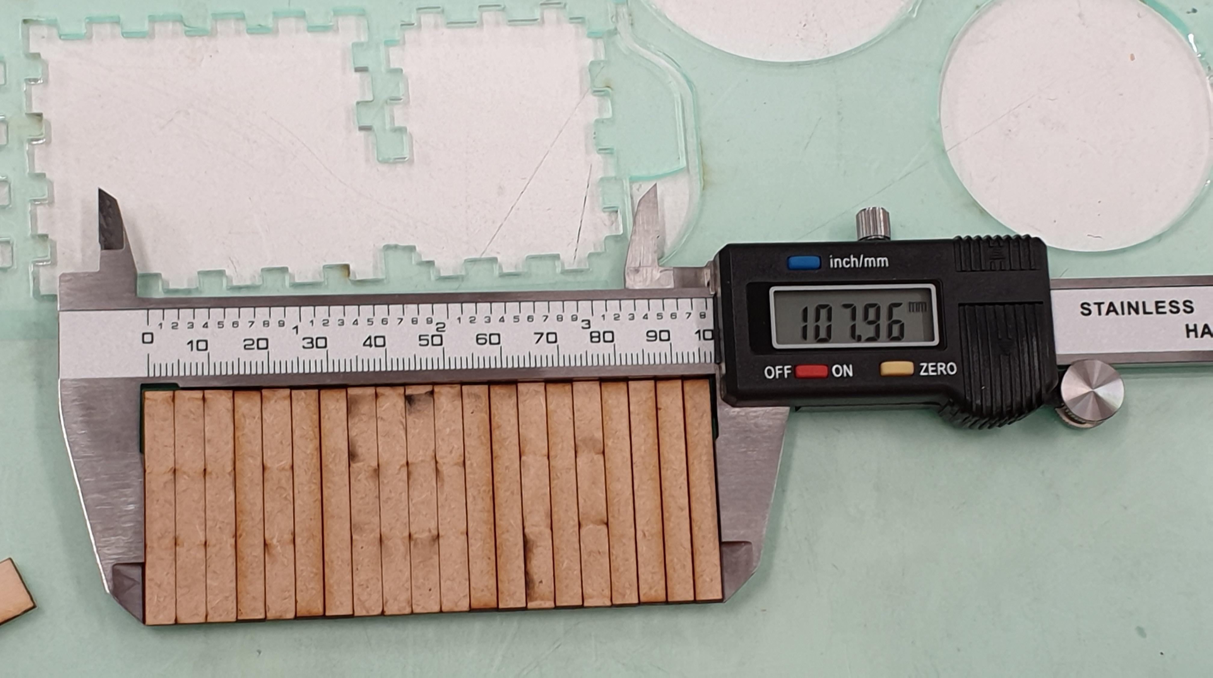
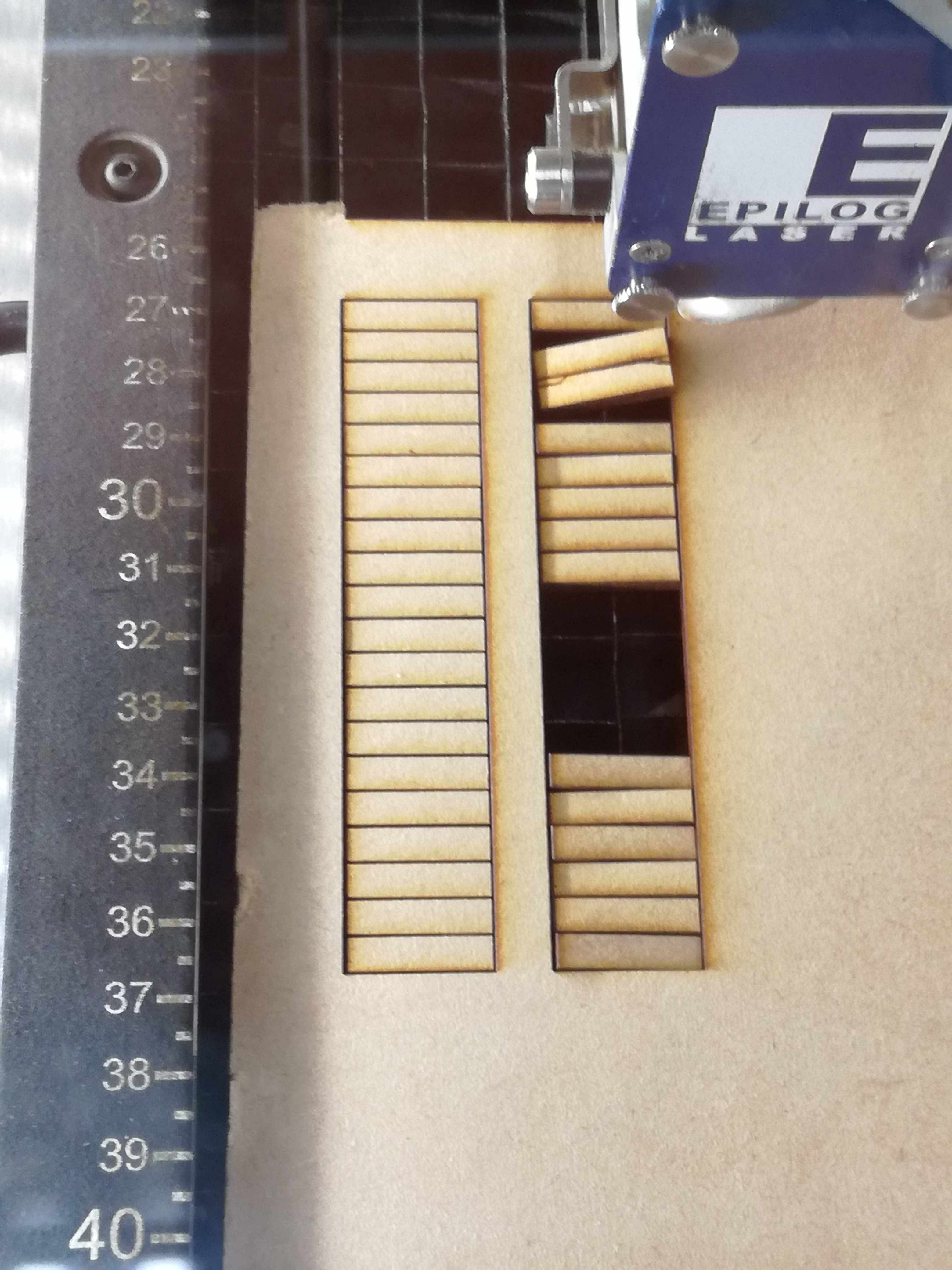
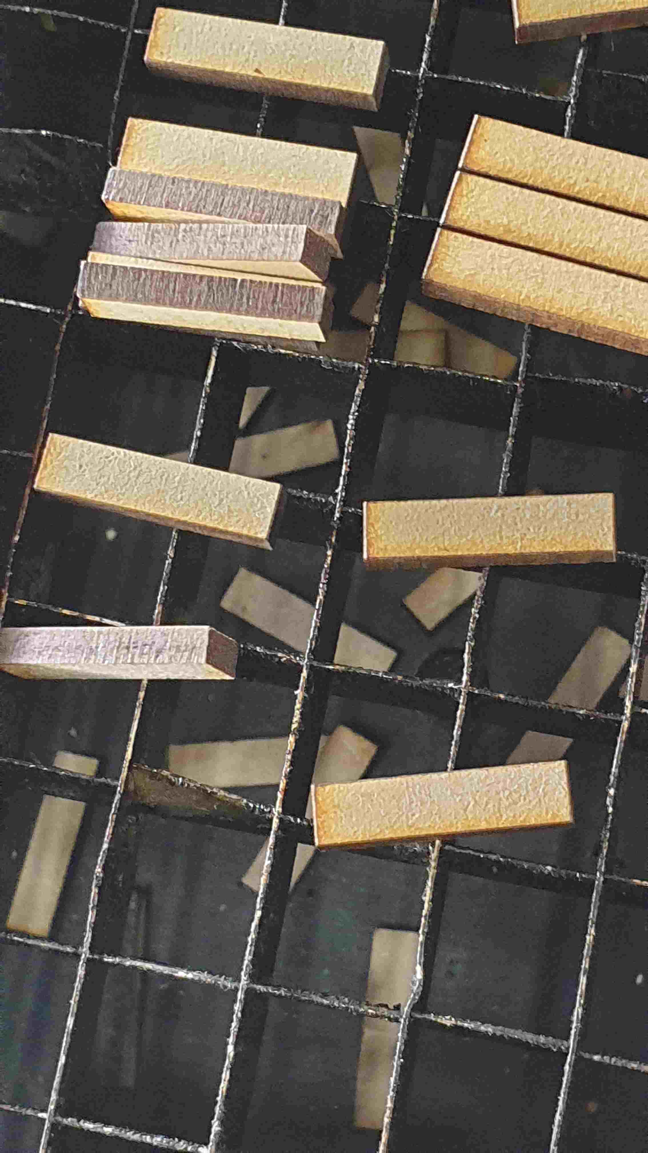
The question is how can we know the kerf? Well, there is more than one answer on that. First of all we can use Goggle. Just click here! But more fun is to calculate kerf by yourself. A bit of Math and 2D Design with Inkscape won't hurt (that much). We (Gleb, Marjo, Perttu and I) decided that we will measure kerf of two materials: MDF and Acrylic. Above images are related. For this purpose we created a "ladder" from rectangles with size of 5 x 20 [mm]. We knew designed height. Nevertheless, measured height was different. We averaged measured error by 20. Moreover, there are parameters other than used material. Those will be mentioned later. Despite of possibility of changing
From our calculations we get values of:
- 0.095 mm for MDF (3mm thickness) - standard presets and correct focus
- 0.22 mm for Acrylic plate (3mm thickness) - standard presets and correct focus
From my own search the value for cardboard is:
- 0.075 mm - for thickness of (1 mm - 6.7 mm)
During the process of measuring Kerf, a lot of things may go wrong. In our case size of designed rectangles were not wide enough because of that we had to change size to 5 x 50 [mm]. Our explanation is that we are trying to stay eco!
At this point it is worthy to mention that kerf is not only connected with the stock material that you are using. Cutter, which you are using has also influence on kerf's value. Note: Our group were using preset values for each material that we examining. Let me name all the things, which may impact kerf value:
- Laser power - value, which is given in Watts [W] it basically defines output power. The more power means more energy, more energy - you may cut more dense materials. However, if you cut paper and metal with 50kW, cut will be different as you will additionally burn edges of paper. This is simple explanation.
- Speed - describes how fast your laser head is moving. This values tell you how much time laser head will spend over a point. In other words how much power you will deliver in an unit of time. Do you remember burning the paper?
- Frequency - The number of laser pulses that the laser fires per inch of travel. The frequency is set in the dashboard and can be adjusted from 1 to 100. A lower frequency number will have the effect of less heat because fewer pulses are being used to cut the material. Lower frequency rates are helpful for products like wood, where charring is evident at higher frequencies. High frequencies are useful on materials like acrylic where a large amount of heat is desirable to melt or flame polish the edges.
- DPI - dots per inch. DPI is used to describe the resolution number of dots per inch in a digital print and the printing resolution of a hard copy print dot gain, which is the increase in the size of the halftone dots during printing. This is caused by the spreading of ink on the surface of the media.Thank you aunt Wiki
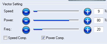
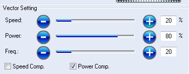
We have experimented with speed of laser head. It really influenced kerf. When we have increased the speed kerf was smaller by 0,01 mm for MDF. Even that change was really slight (8% => 13 %)
Individual Assignment
Vinyl cutter
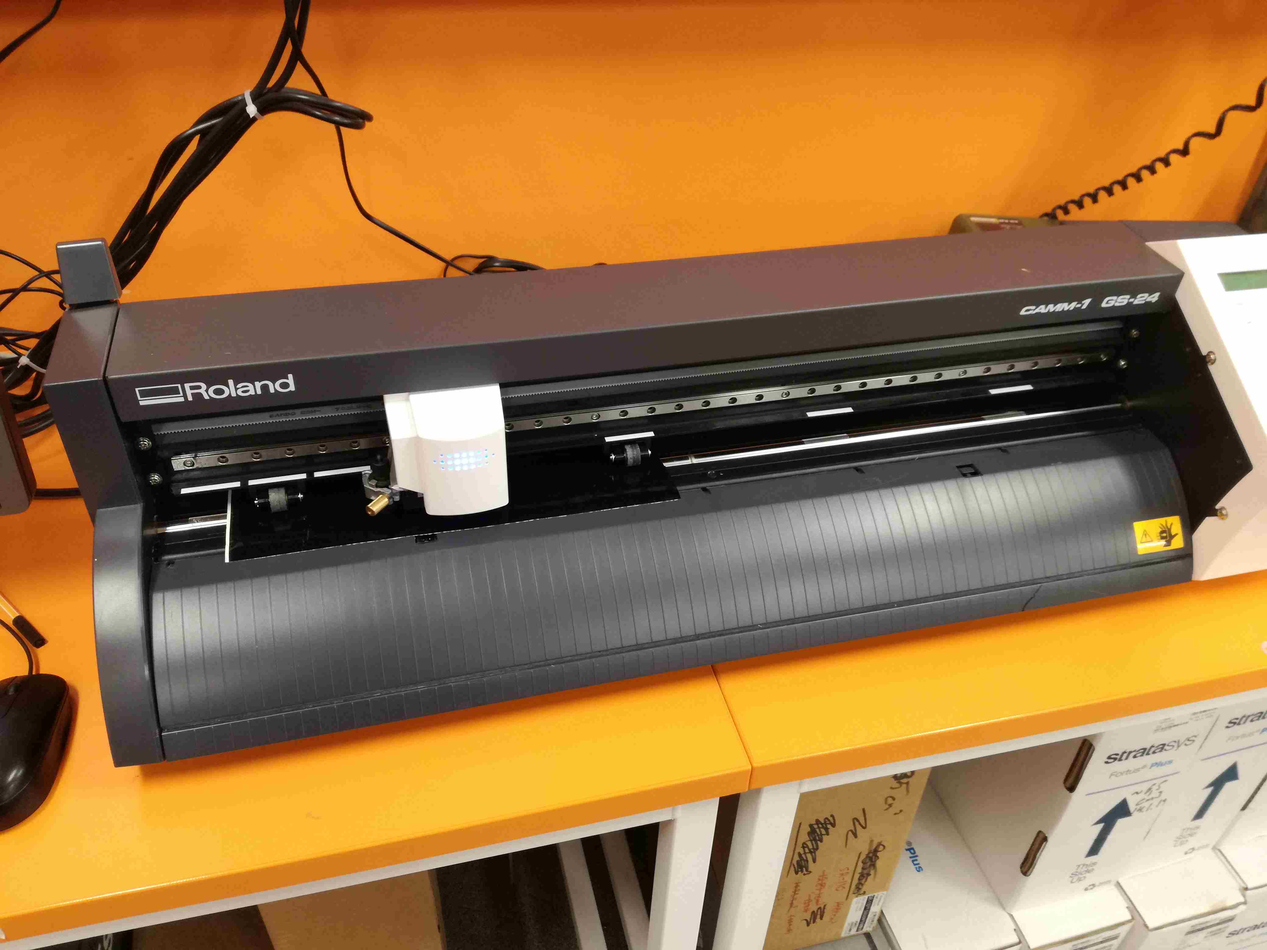
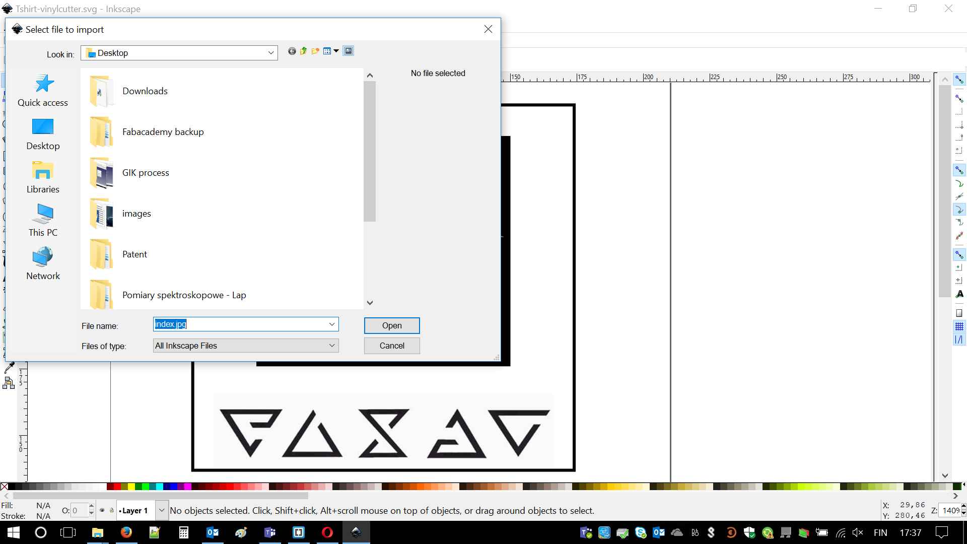
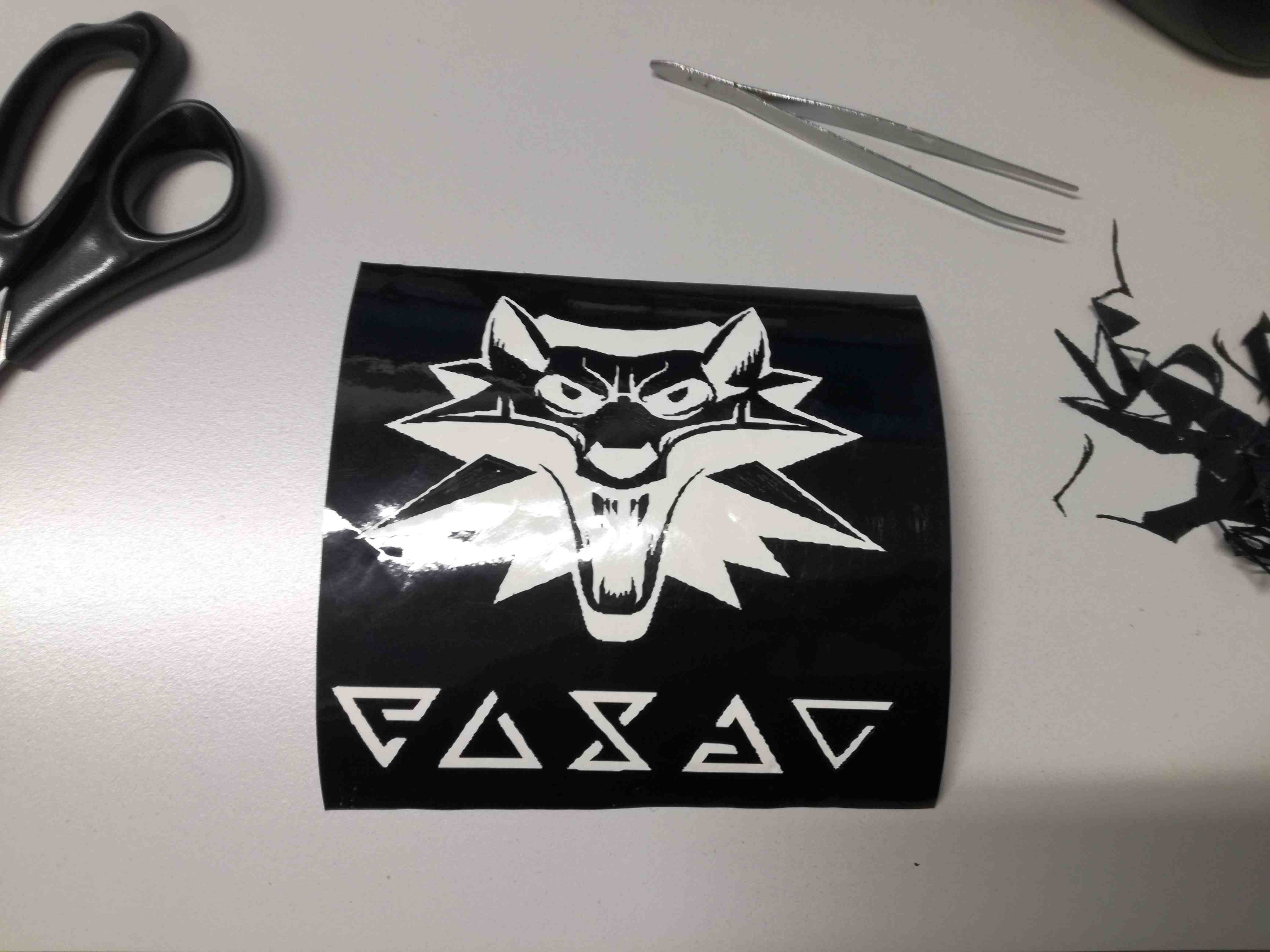
Available vinyl cutter is Gamm-1 GS-24. We are also lucky, as we might use T-shirt press in our Fablab in Oulu. I decided to use Inkscape for my design. It was pretty convenient as there is "Import" tool. What I needed to do is just simply find some black and white images (even that I got a bit of red it does not matter as far as I remember that everything will be in single color. I decided that I will create something with Witcher as I love books and games featuring Geralt. I simply used a logo of the Witcher 3 game and combined it with Witcher's signs. I was surprised how well it matched.
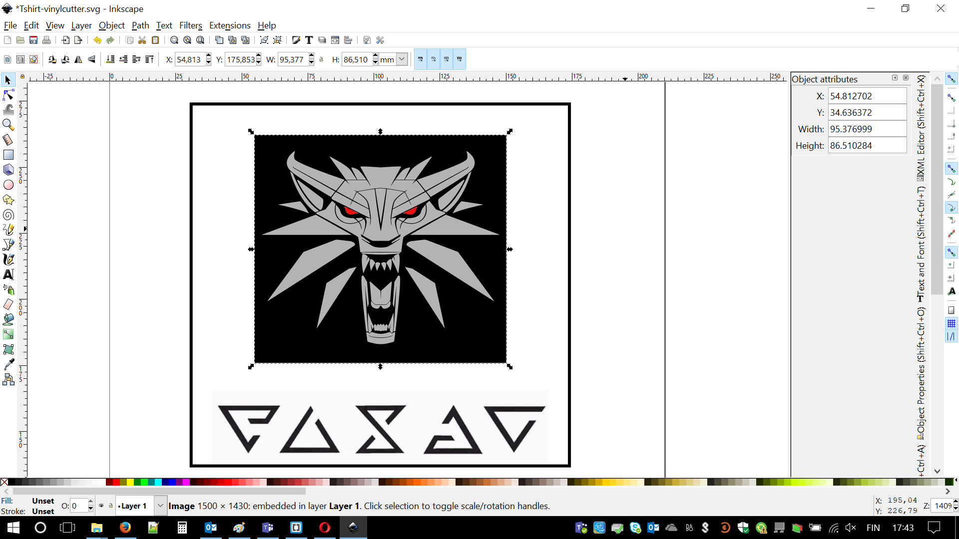
I was sure I'm ready to cut. Then I faced reality. First of all, vinyl cutter is very similar to laser cutter but there is blade not stream of photons, which is making the cut. Previous design was way too complex. Even if cutter would be able to cut all of this lines(some of them would be very thin) there is another problem. Some of them are not even 'closed', I have to ensure that blade is following some pattern. At this moment I decided to simplify my drawing. Screenshot related to it is just below.
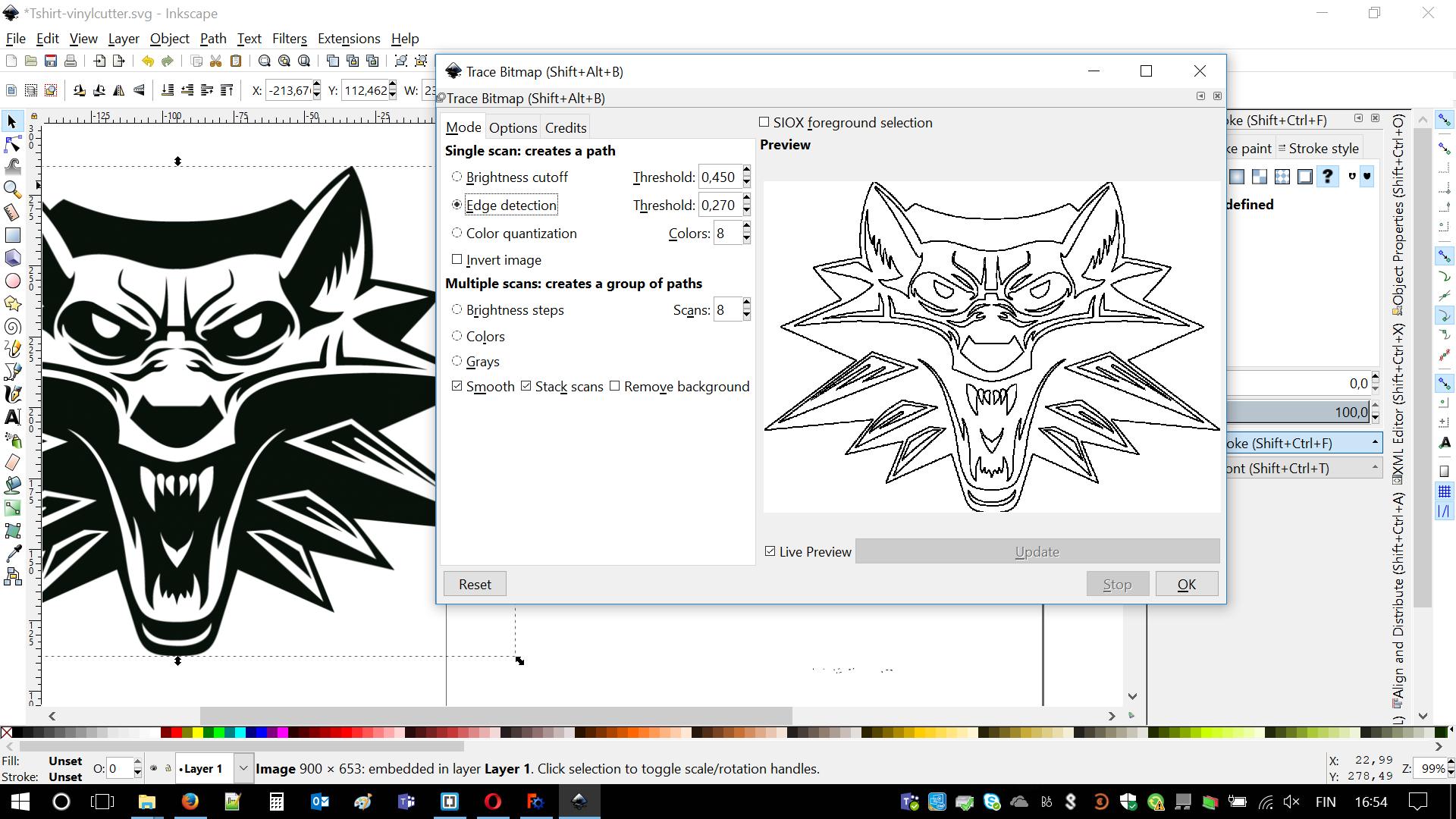
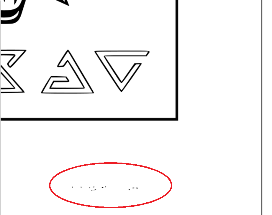
There is also another problem. I downloaded images, which are portable network graphics (PNG). This is not vector image. In order to change it into file readable by cutter. In order to do it I had to Highlight the area > Path (menu) > Trace Bitmap and in there set some values, e.g. by edge detection. I did the same with signs symbols (below the wolf head).
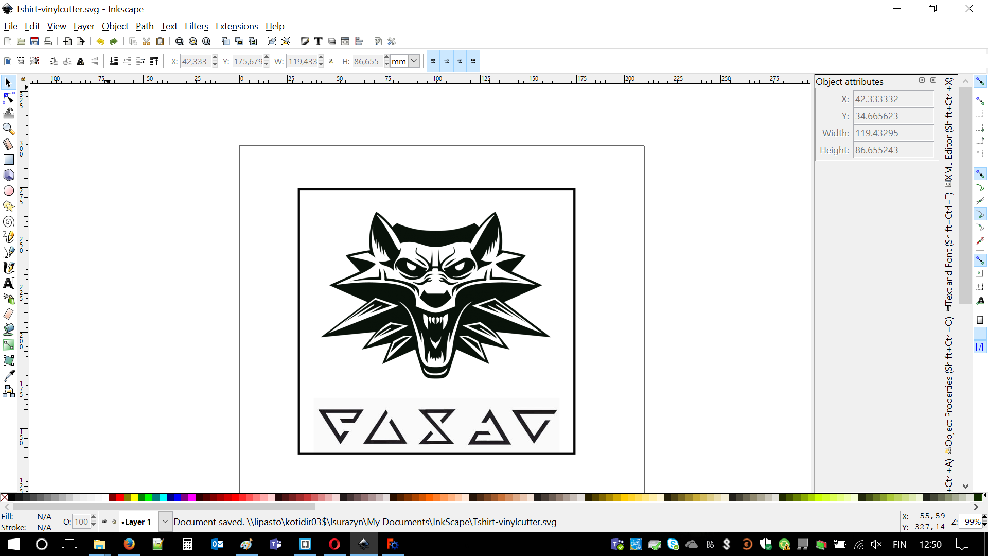
There are some unwanted artifacts. This might lead to extending size of required material. I had to remove them by selecting this part. Using Object/Ungroup then Path/Break apart, finally deleting this artifacts.
After I cut out my Witcher medallion I carefully sheared unwanted material. Effect was decent. I liked it. My choice was parameters was: highest blade force value (4) and blade width of (200) micrometers. Eventually I should place it on transfer material and attach/glue to my desired place. I could do it with my laptop but I like how does it look right now :)
After finalizing this part of the project I will write the schedule or procedure of working with vinyl cutter. I feel it might be handy in the future. At this point, it is important to remember that we are able to cut from several different materials, depending on the future purpose. However procedure is similar in every case. We are following these steps:
- Import your .SVG file onto the software and choose placing - bottom left corner.
- If necessary, create mirror image.
- Lift lever blocking rollers.
- Adjust blade depth (value 1 to 4)
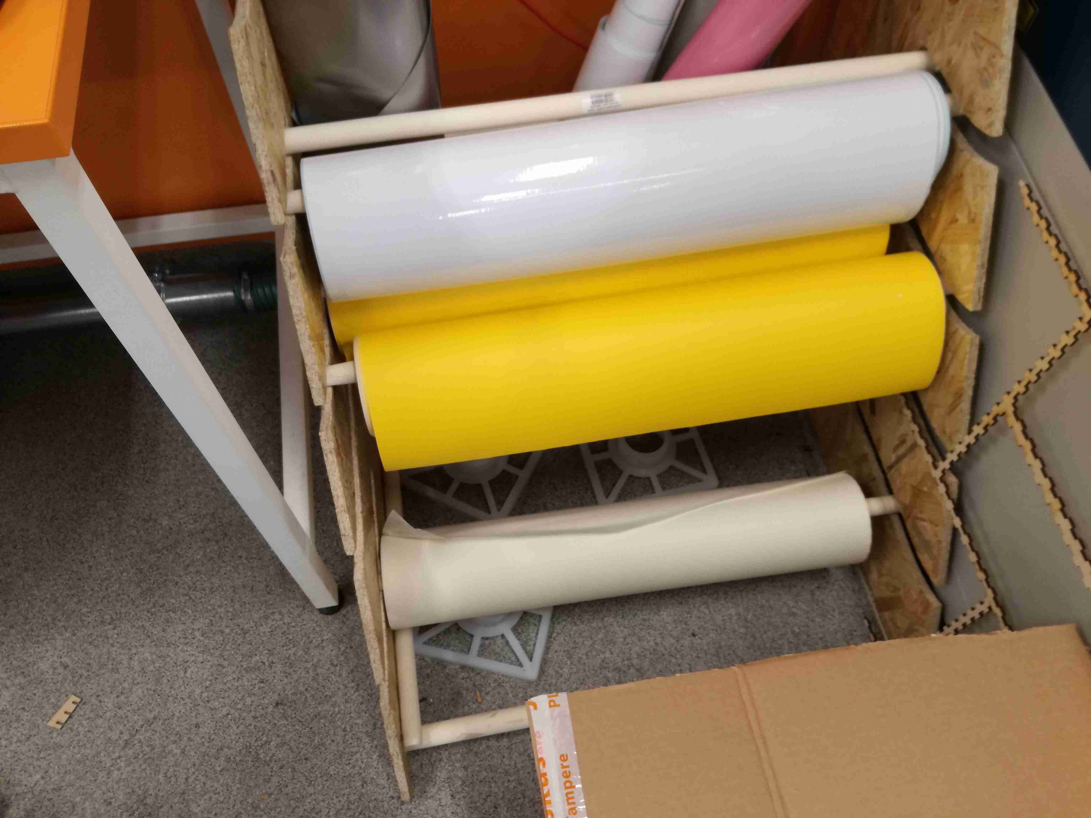
- Choose proper stock material and place it in the cutter, starting from the back.
- Adjust roller positions, they have to be in marked places.
- Clamp the lever, material is now being hold by rollers.
- Measure the size of the material using vinyl cutter, remember about two modes: edge and total length
- Import size 'from the machine' in the printing dialog.
- Manually insert length size with a value slightly bigger than length of the design
- Set origins on bottom left side (X=0, Y=0)
- Press OK and enjoy!
- Take out your design when it indicates finishing the process. Use lever to release it.
- Remove unwanted parts by shearing, (
not by lifting) - Attach to the transfer material
- Finally, glue to desired place or create T-shirt with the press
Press-fit construction kit or so-called GIKs
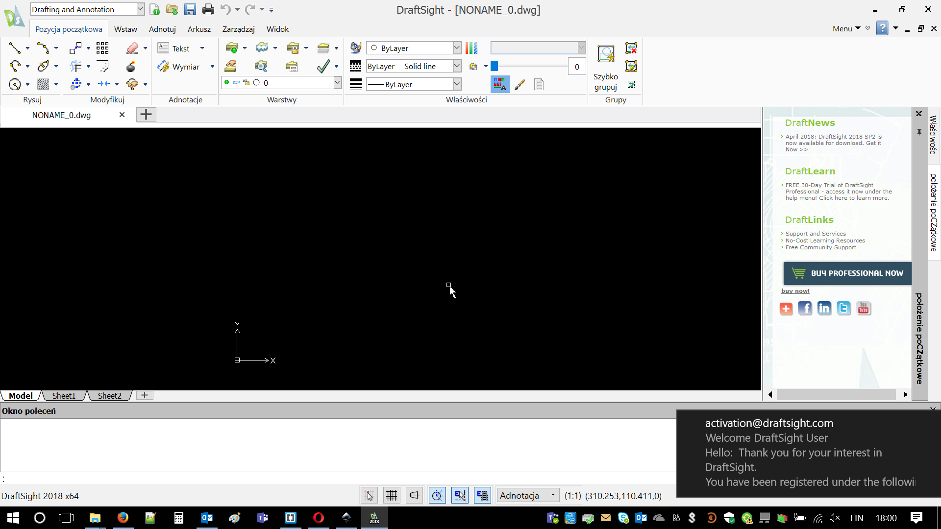
Vinyl cutting was quite simple. Now this is time for some real engineering. In order to design my versions of GIKs I decided to download Draftsize 2018 using this link: Click . I successfully passed activation part as Draftsize is not free to use. Opened it and decided to use FreeCAD.
The main reason is that I can but also I would need to learn how to use it. In the future in case I need to design something i would need to pay. Well, long live Freeware! Actually after first mistakes and issues I discovered that FreeCAD is not that bad and kind of liked it. I'm sure I just touched abilities of this 'truck'. Still I feel it would be much easier in the future. In upcoming final project.
Once again I was using youtube tutorials. Especially this two were most important: FreeCAD parametric design The part design workbench. In case of any problems I was googling name of issue. - Allright, Capt. Obvious. Ah, when I was designing I was listening to: Dead Man's Opera Might be important info in the future.
Well, I failed quite much on the beginning. My lines were not connected to each other. Everything was falling apart. When CAD informed me that my figure has 56 degrees of freedom I was even wondering how this is possible. Then I decided I will spend much more time than first 10 minutes of each tutorial. I learned how to connect lines (simply wait for little dot to appear) and how to put constraints. Those are really important and basically describes how drawings are relating to each other.
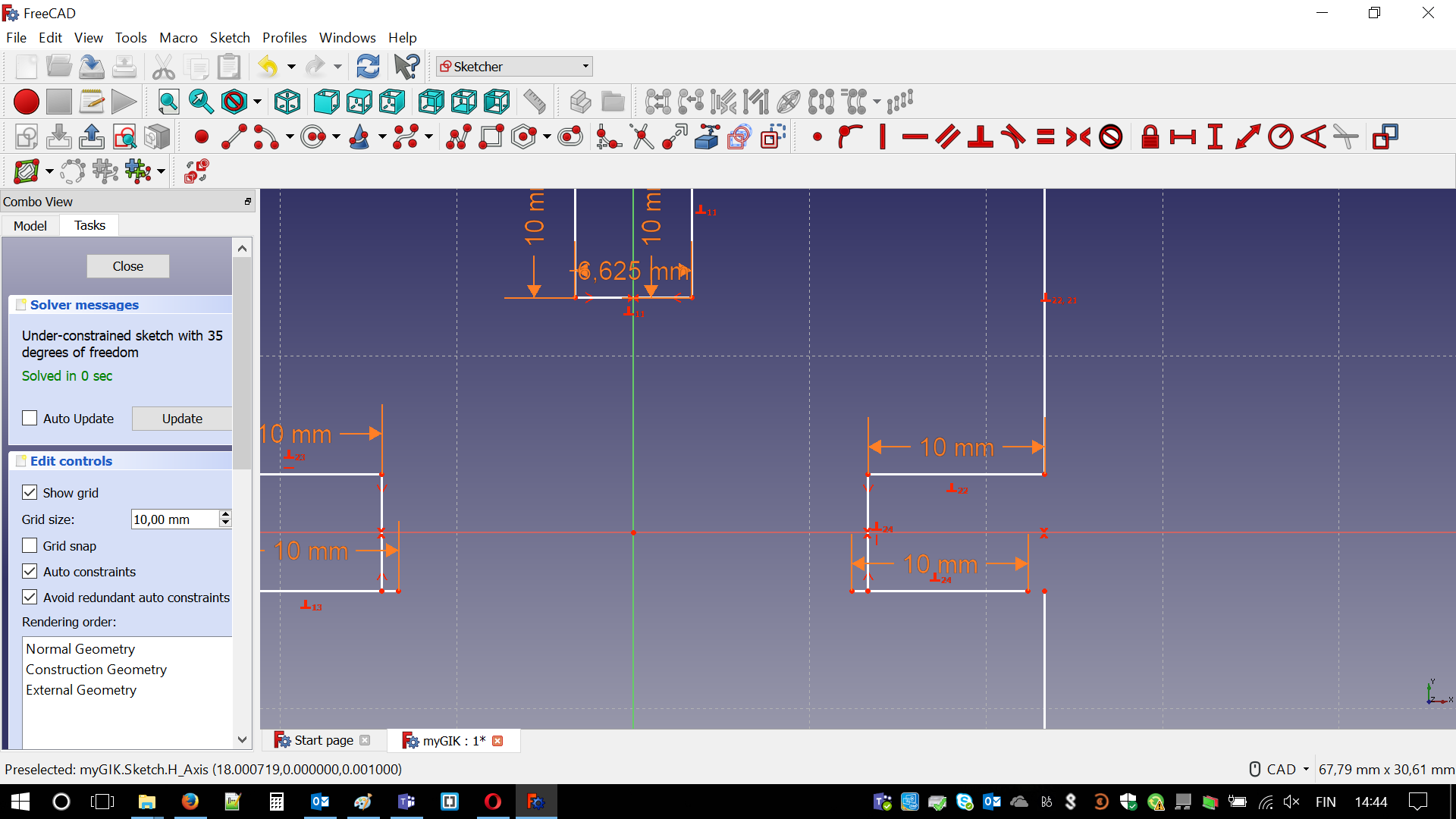
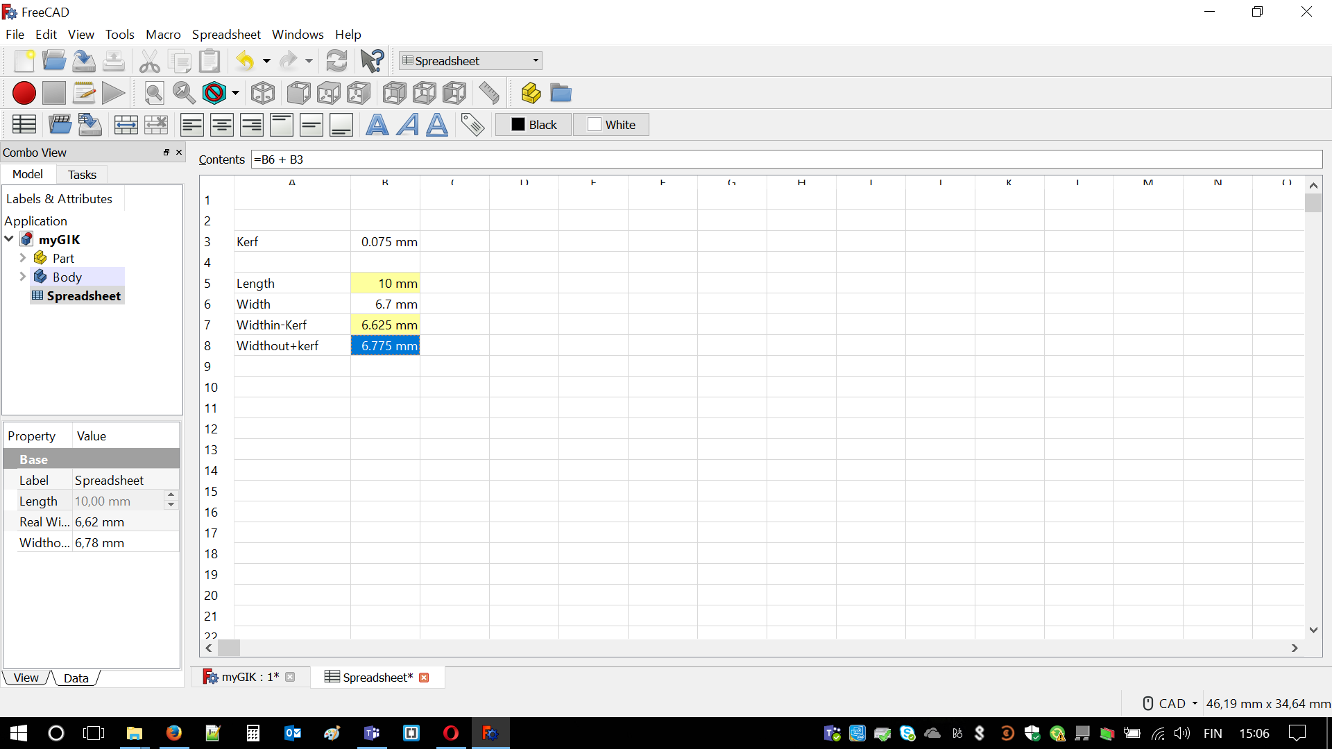
Then I learned how to design with parameters. In order to do it knowledge how to properly use Spreadsheets and is necessary. I created variables:
- thickness - for given material
- width of holes - thickness + kerf(for specific material)
- depth of holes - depending on size of my GIKs
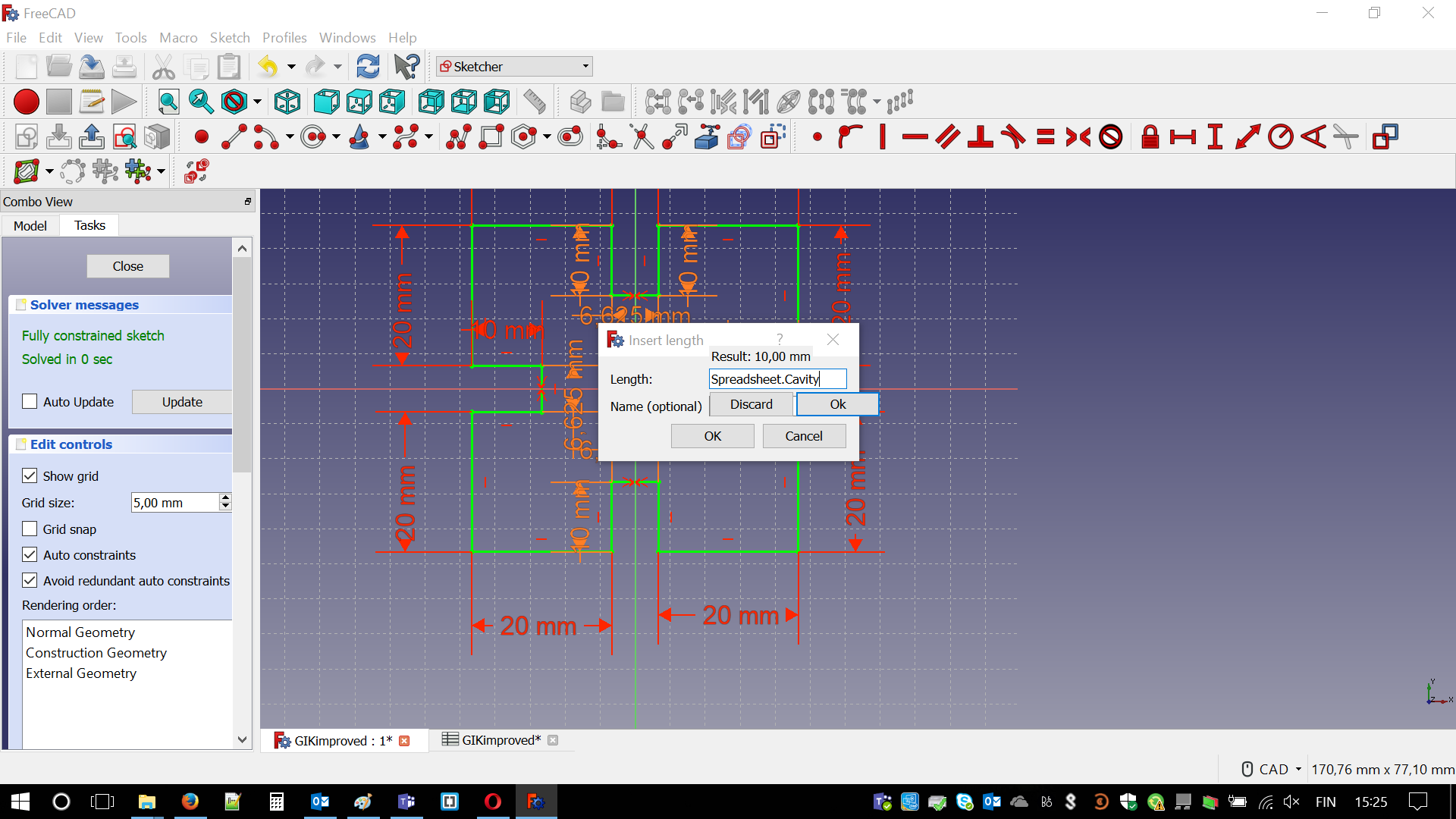
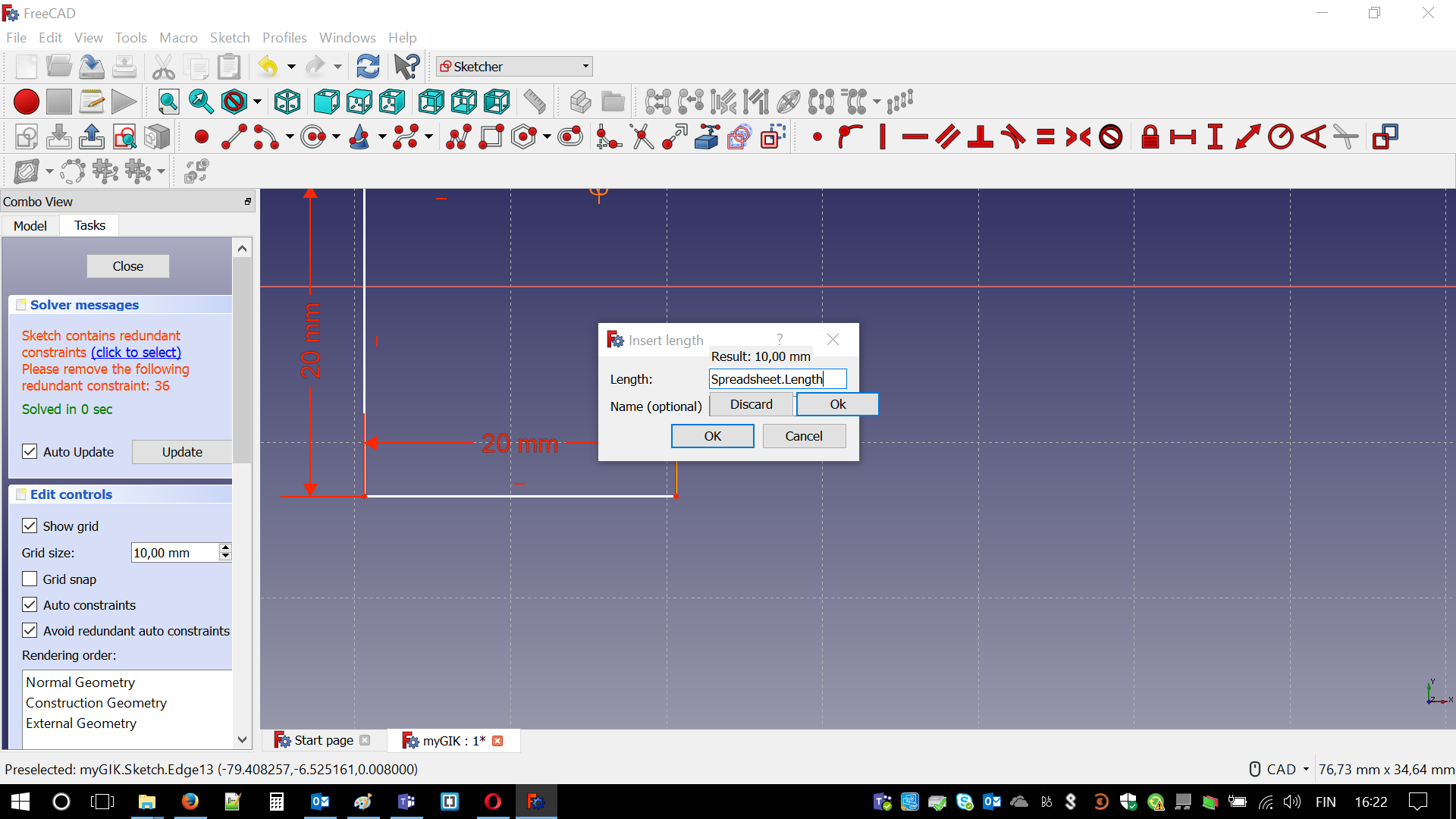
Then I was able to assign names to lines. Now simply with two clicks I could change their values(all at once). Meaning, I could fix kerf values for different materials. It is not even that important where are you placing your spreadsheet. It just has to be attached to the part you are designing, as naming is done automatically with all those # @ $
used with file path.
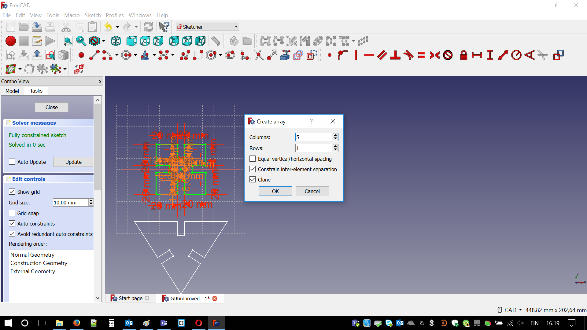
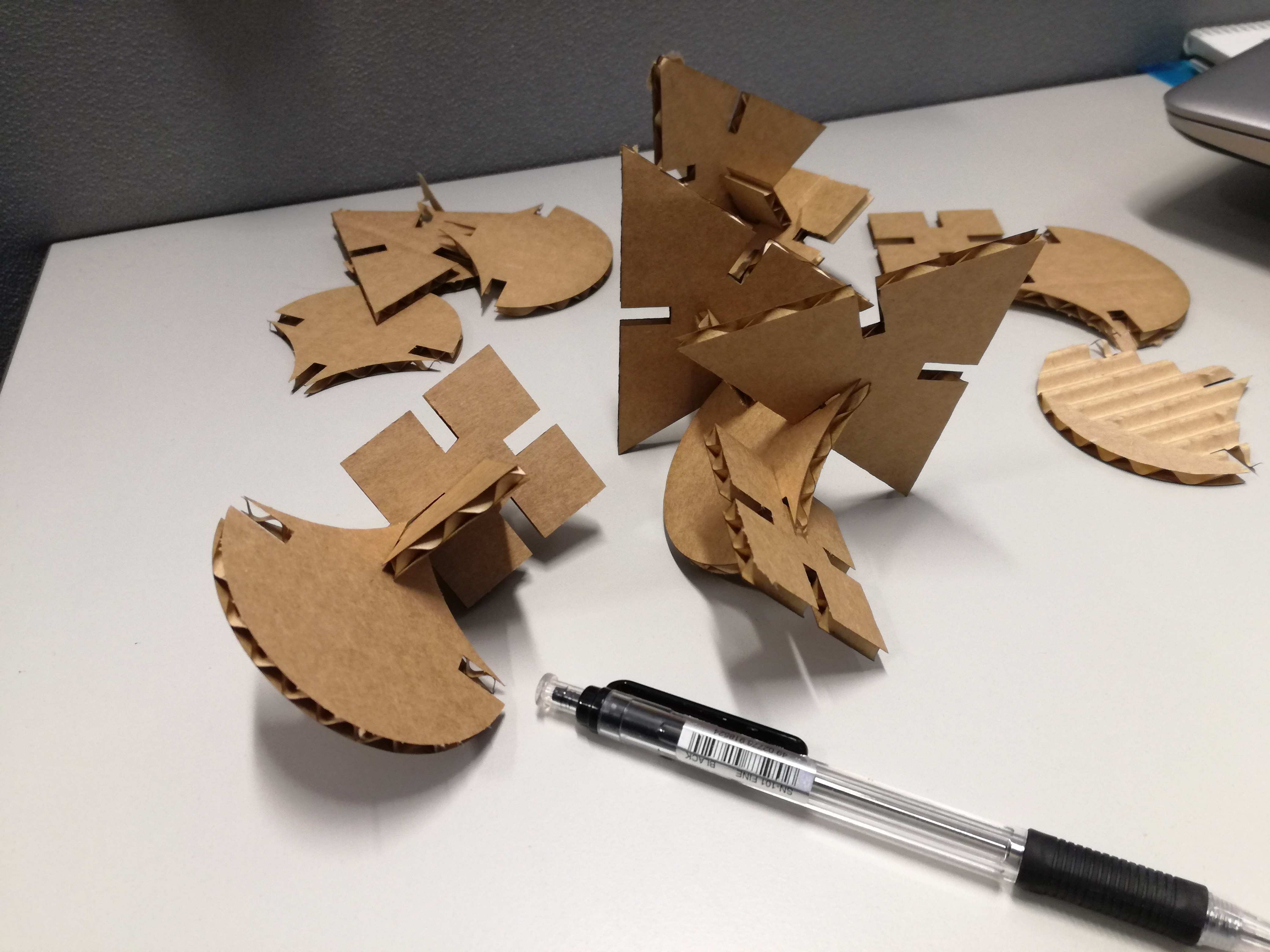
I decided that I will design 3 different parts. One square, one triangle and last one, which is combination of different shapes (arcs, lines etc.) This is how process ran:
When I had two parts ready I decided to use CLONE function to multiply my pieces. It was fairly simple. I just had to choose distance between them. It might have been done better - just smaller spacing would save a bit of cardboard.
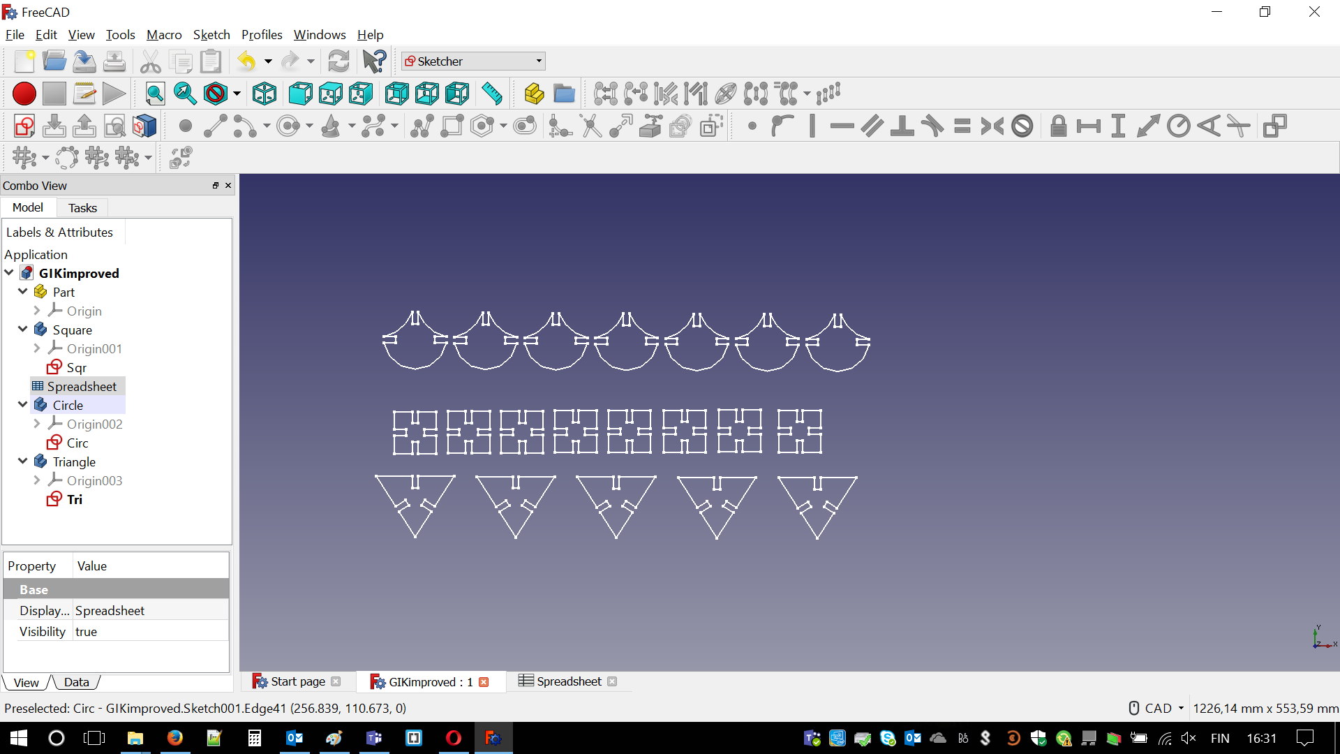
Finally, I created three rows, each for different piece. 7 circle-like pieces, 8 squares and 5 triangles. Hopefully, I would be able to create some nice object with it. Below final result just before cutting. Ha! I forgot to answer on the most relevant question in design matter. What is the purpose of parametric design? Once again, please let me quote aunt Wiki:
Parametric design is a process based on algorithmic thinking that enables the expression of parameters and rules that, together, define, encode and clarify the relationship between design intent and design response.
Parametric design is a paradigm in design where the relationship between elements is used to manipulate and inform the design of complex geometries and structures.
The term parametric originates from mathematics (parametric equation) and refers to the use of certain parameters or variables that can be edited to manipulate or alter the end result of an equation or system. While today the term is used in reference to computational design systems, there are precedents for these modern systems in the works of architects such as Antoni Gaudi, who used analog models to explore design space
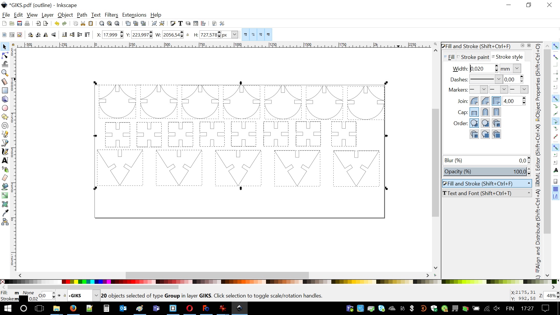
Laser cutter is able to read PDFs, which are saved as vector graphics. Once again vectors, vectors everywhere! Fortunately, this is not a big deal. What is needed is a bit of goggling and Inkscape (at this point I seriously started to like it functionality). The process of changing sketches into vector graphics in FreeCAD goes like that:
- Change view from Sketcher to Drawing
- Press CTRL and mark all sketches that you need (as I created every GIK as different part)
- File - Export - Choose Flattened SVG
- Choose destination and save it
Now it is time for some magic with Inkscape. First of all it is important to "Ungroup" your pieces, which are one big image. After that by pressing CTRL+A it is necessary to highlight all pieces. In Object > Fill and stroke there are all important settings. There should be no fill, Flat color is a stroke paint and line width is 0.02 mm. Everything will disappear but it is totally normal. Lines become very thin. In order to bring them visible it is important to adjust View settings by View > Display Mode > Outline. File is ready to be saved as PDF.
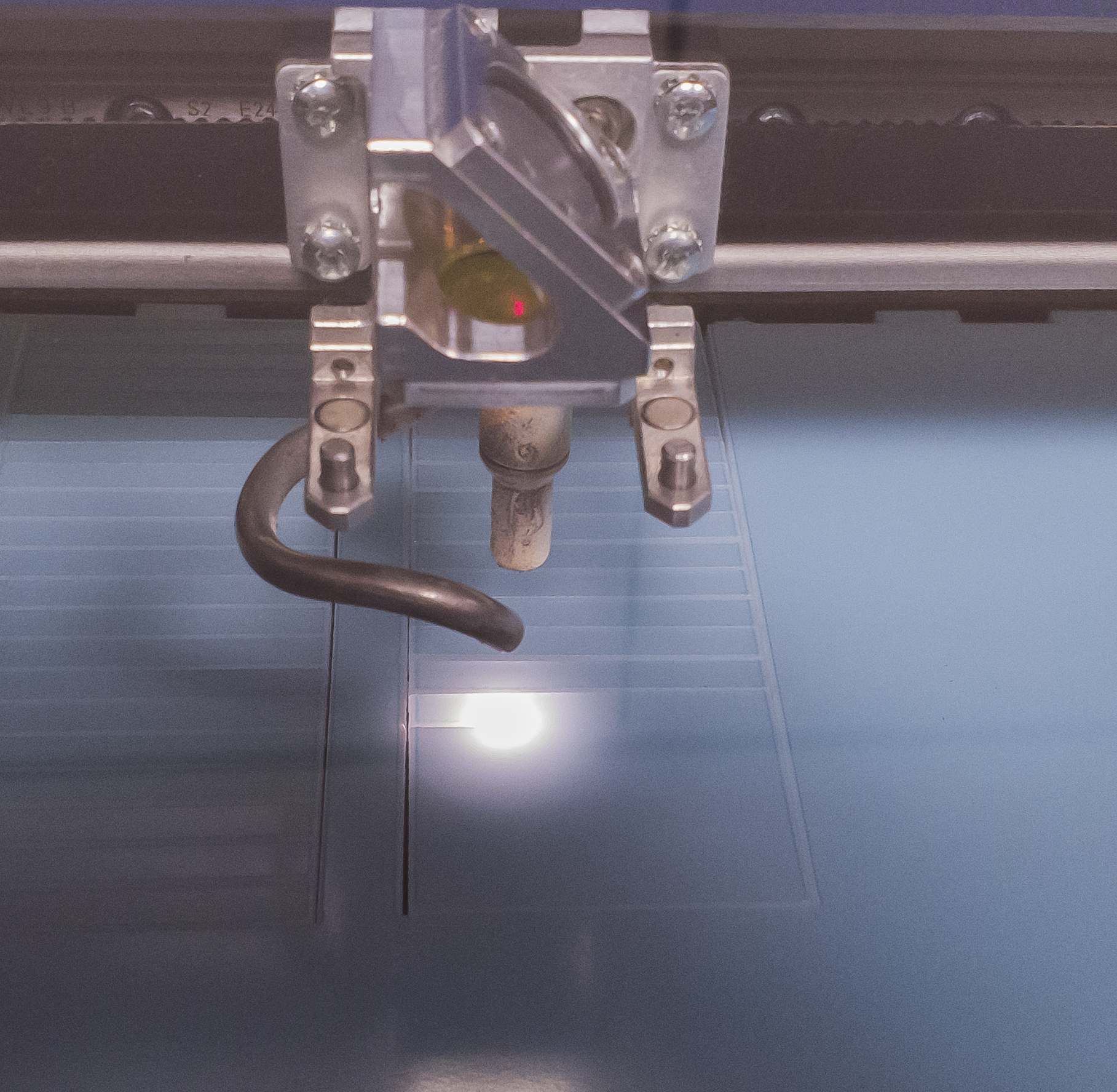
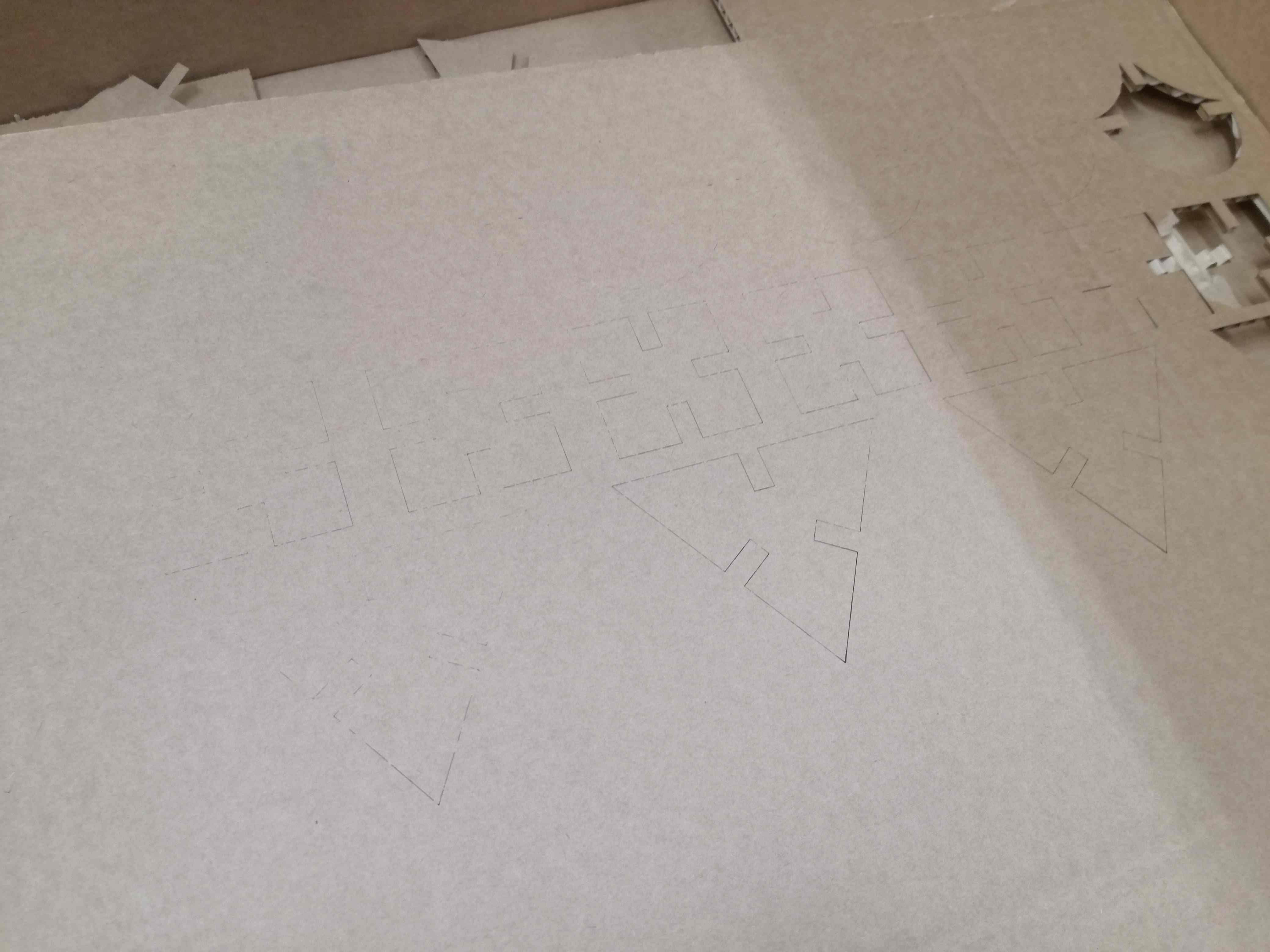
We ran out of 6.7 mm cardboard. I had to change the thickness to 4.8 mm. Boom! I had everything designed as parametric. It was just couple clicks. I changed internal width of the holes. It automatically changed all the values and sizes on the sketch (taking kerf into account). Here is the procedure of using laser cutter:
- Place stock material in the chamber
- Adjust focus using little triangle tool, it should slightly touch the material
- Use joystick to lift or drop the laser table
- Note: you may use fast or slow mode (Joystick right)
- Press joystick after you are done, note zeroing of displacement
- Adjust starting position (JOG):
- Use joystick to move left/right. Red dot is indicating starting point
- Note: starting point is top left point of your PDF
- Press joystick after you are done, note zeroing of displacement
- Print PDF using Adobe Acrobat or similar software
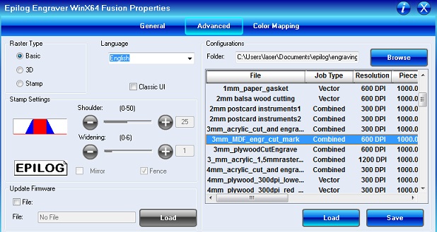
- Load correct presets for your material
- Check General (tab)
- Confirm printing
- Find your file in section JOB (on your laser cutter)
- Press START and observe if nothing is burning
- Wait a moment and take out your "results"
Did I mention that cardboard sucks? Alright, this is the time then :). In general process was successful. Still, cardboard is not entirely flat. It bends. No weight, tape or BluTack will fix it. It looks like cardboard is resistant to any force (except water and fire). This changes focus, which influences the kerf. Some of my GIKs are alright. Some of them are not fitting that well. Nevertheless, I learned my lesson. Below couple photos of my connected pieces and problems with cut (It had to be repeated). Lastly, I would improve the design for the future. Holes should be placed in some bigger distance. Furthermore, cavity(hole) length could be a ratio of the each piece size. Currently those are also parametric values but no relation.
Files:
Download: GIKs - FreeCad fileDownload: GIKs - STL
Download: GIKs - PDF
Download: Speed vs Power test files - PDF
Download: Speed vs Power test files - SVG
Download: Witcher logo