14. Networking and communication
This week I learnt how to make a communication between boards.
I²C communication
I²C communication works by master nodes and slaves nodes, connected to share data through by SDA (Serial DAta) and SCL (Serial CLock) ports.
Master nodes generate the clock and initiates communication with slaves; slave nodes receive the clock and respond when addressed by the master.
Test
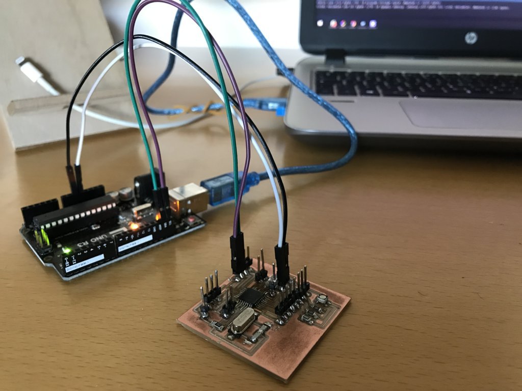
I test the I²C communication codes respectively programming and then connecting an Arduino UNO and the satsha kit I made.
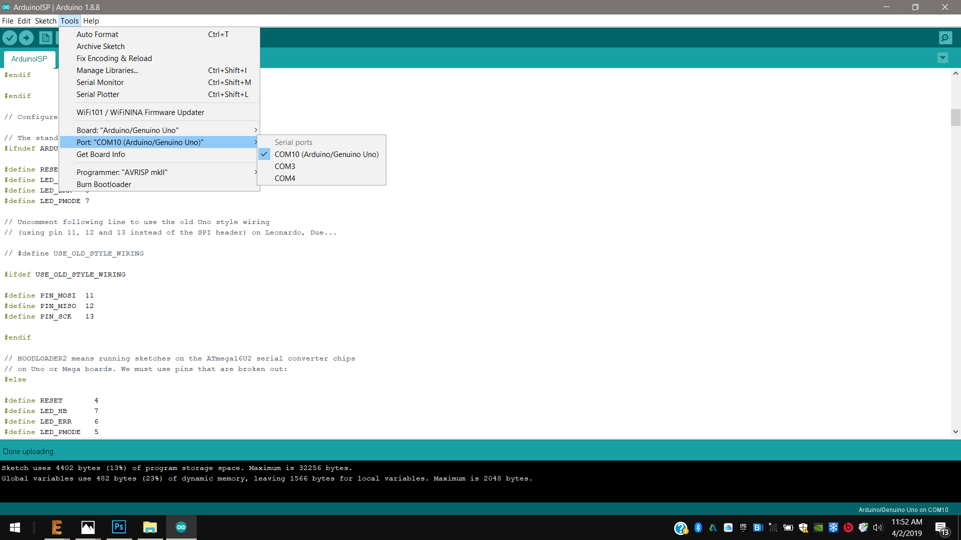
1st I enabled the Arduino UNO as programmer, opening and uploading the Arduino ISP example on Arduino IDE.
2nd Then I connected the satsha kit and I programmed it as slave.sender;
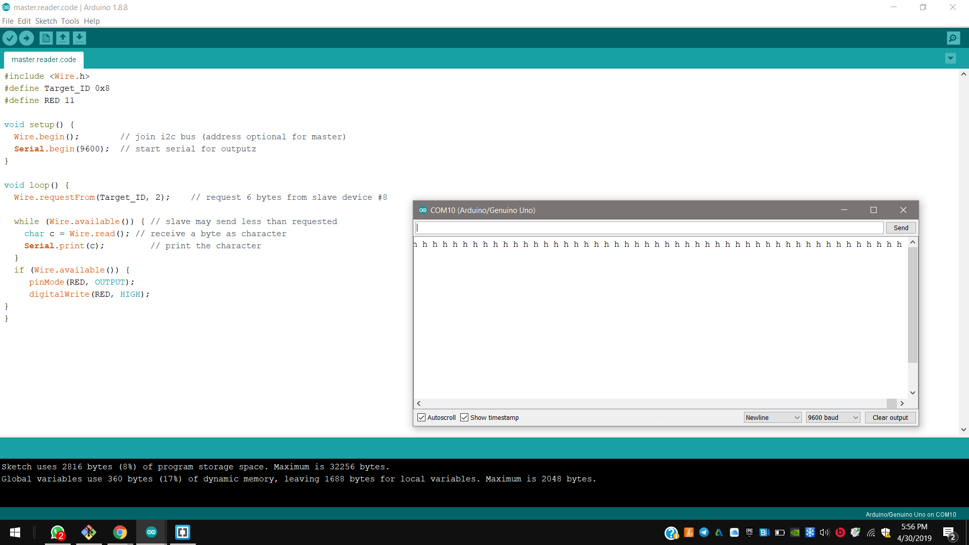
3rd I reset the Arduino UNO, and I uploaded the master.reader code.;
4th And I connected them again just through SDA and SLA, and I could read data opening the IDE serial port.
Atega328p and Attiny44 communication
Then I made a communication between two boards I made, one with an Attiny44 and the Atmega328p, programming and reading the same data codes of the previous test.
I respectively programmed the satsha kit as master reader and the Attiny44 as slave sender; then I connected the master to FTDI module RX pin to send messages and read them by serial.
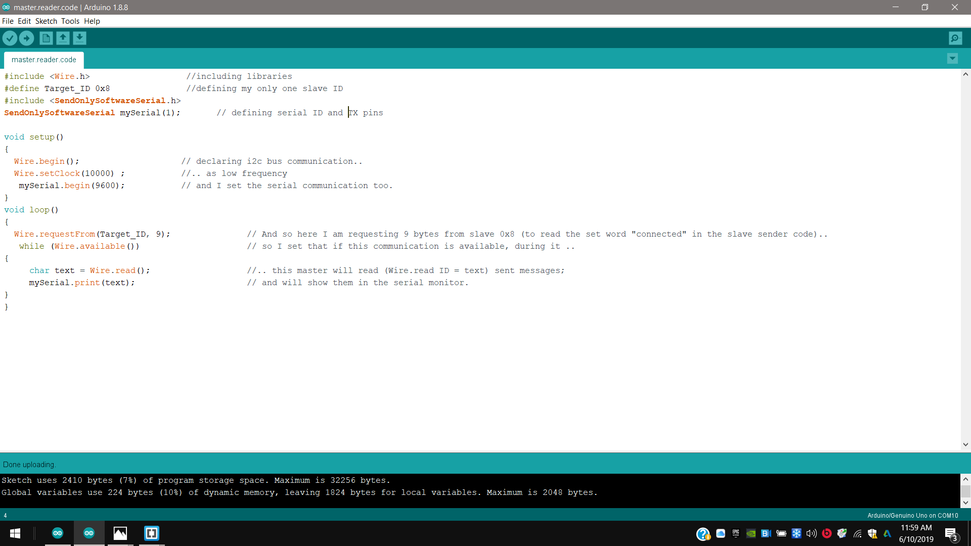
Programming master reader
1st I connected the satsha kit I made to the Arduino uno to program it as master reader.
On Arduino IDE:
2nd I included the Wire.h library of IDE;
3rd I defined the serial communication begin and the I²C address for the master (0x8) and the serial ID and RX - TX pins;
4th Then I defined the functions to start the communication as low frequency (10000 Hz) and I set the serial communication too;
5th so here I am requesting 9 bytes from slave 0x8 (to read the set word “connected” in the slave sender code), and I defined the “Wire.read” ID to specify and show them in the serial.
#include <Wire.h>                   //including libraries
#define Target_ID 0x8               //defining my only one slave ID
#include <SendOnlySoftwareSerial.h>
SendOnlySoftwareSerial mySerial(1);       // defining serial ID and TX pins, just to send messages to serial monitor

void setup()
{
  Wire.begin();                    // declaring i2c bus communication..
  Wire.setClock(10000) ;           //.. as low frequency
   mySerial.begin(9600);           // and I set the serial communication too.
}
void loop()
{
  Wire.requestFrom(Target_ID, 9);               // And so here I am requesting 9 bytes from slave 0x8 (to read the set word "connected" in the slave sender code)..
   while (Wire.available())                     // so I set that if this communication is available, during it ..
{
     char text = Wire.read();                   //.. this master will read (Wire.read ID = text) sent messages;
     mySerial.print(text);                      // and will show them in the serial monitor.
}
}
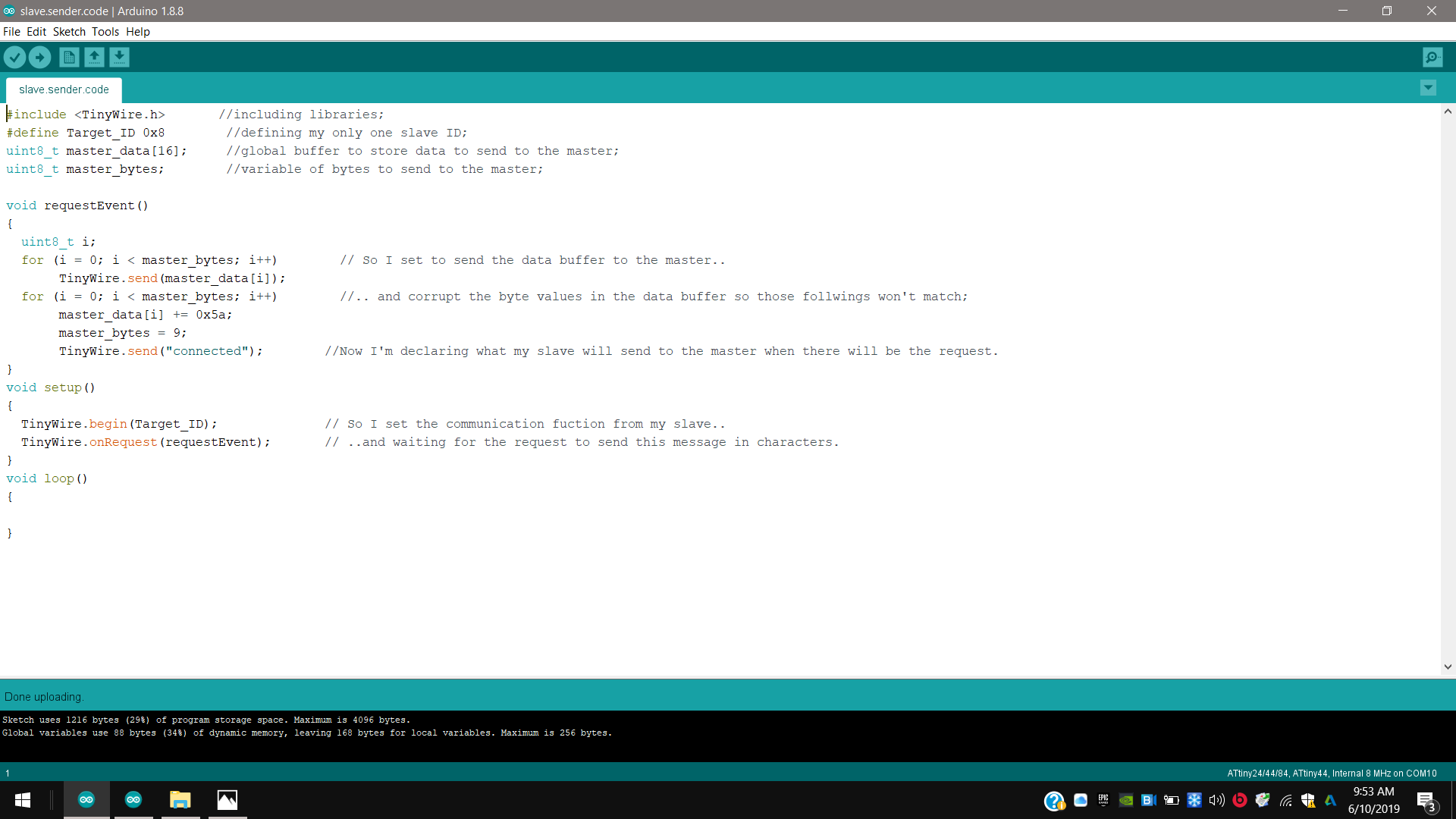
Programming slave sender
1st I connected the satsha kit I made to the Arduino uno to program it as master reader.
On Arduino IDE:
2nd I downloaded and included the last version of TinyWire library that includes master and slave ones;
3rd I defined the serial communication begin and the I²C address of the slave;
4th Then I I set to send the data buffer to the master and corrupted the byte values in the data buffer so those follwings won’t match;
5th And I set the communication fuction from my slave, waiting for the request to send the message in characters;
#include <TinyWire.h>       //including libraries;
#define Target_ID 0x8        //defining my only one slave ID;
uint8_t master_data[16];     //global buffer to store data to send to the master;
uint8_t master_bytes;        //variable of bytes to send to the master;

void requestEvent()
{
  uint8_t i;
  for (i = 0; i < master_bytes; i++)        // So I set to send the data buffer to the master..
       TinyWire.send(master_data[i]);
  for (i = 0; i < master_bytes; i++)        //.. and corrupt the byte values in the data buffer so those follwings won't match;
       master_data[i] += 0x5a;
       master_bytes = 9;
       TinyWire.send("connected");        //Now I'm declaring what my slave will send to the master when there will be the request.
}
void setup()
{
  TinyWire.begin(Target_ID);              // So I set the communication fuction from my slave..
  TinyWire.onRequest(requestEvent);       // ..and waiting for the request to send this message in characters.
}
void loop()
{

}
Connection and communication
Slave sender due to reasons of connetions has always to process as first.
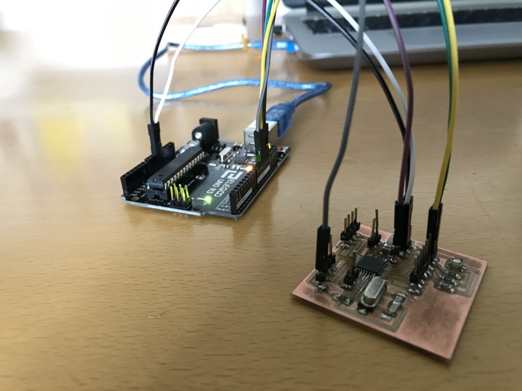
1st I charged them with the Arduino UNO and a breadboard;
2nd I connected the respective SDA and SCL ports of the boards;
3rd And I connected the TX pin of hte satsha kit micro master to the RX pin of the FTDI module.
In this video the signals aren’t converted in text due to problem of interference.
Downloads
.zip
TinWire library
.ino
master reader code
master.reader.serial.print.ino